Assessment of Capacitance for Self-Excited Induction Generator in Sustaining Constant Air-Gap Voltage under Variable Speed and Load


Abstract
1. Introduction
1.1. Self-Excited Induction Generator
1.2. Literature Review
1.3. Paper Overview
2. Materials and Methods
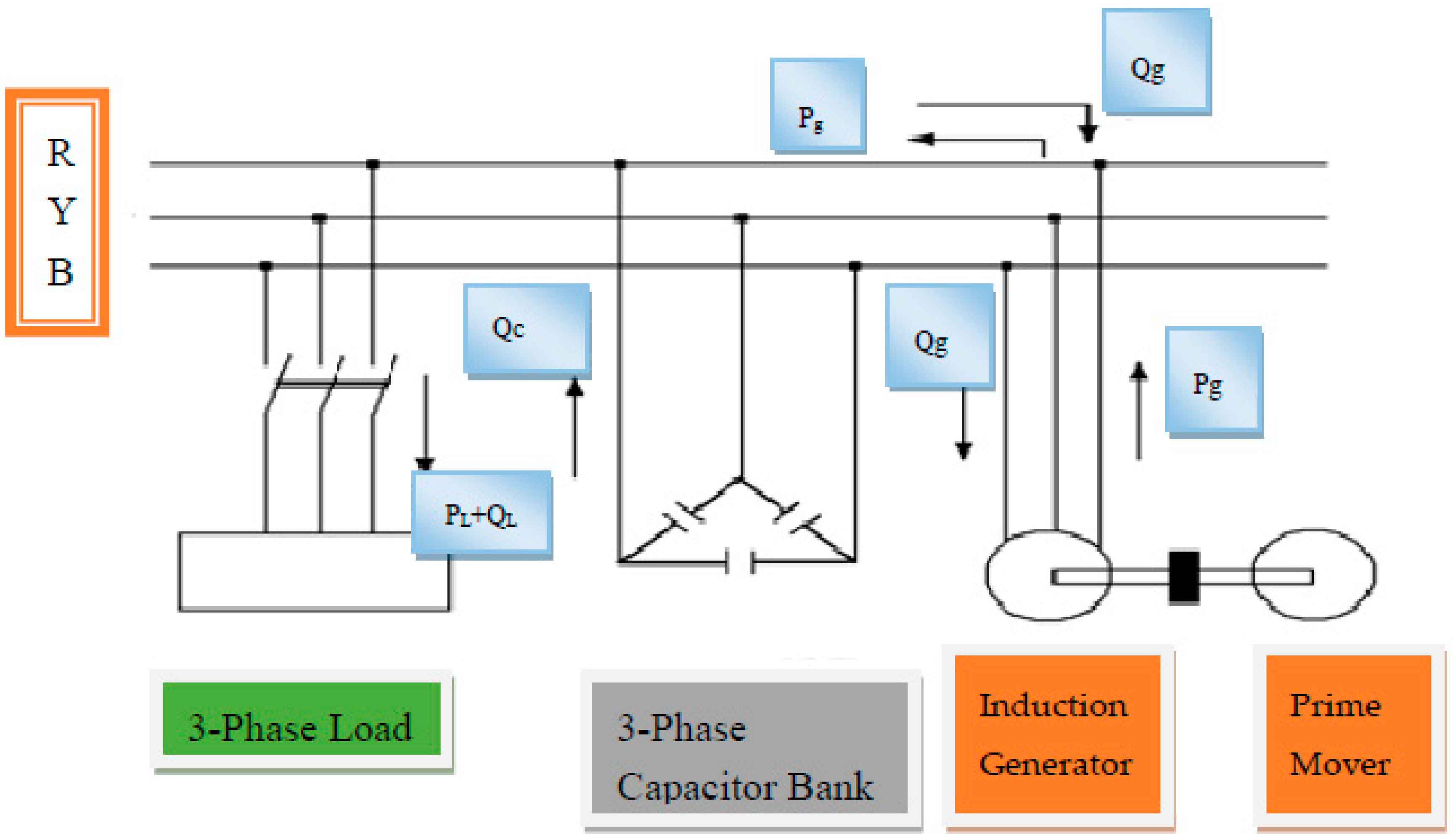
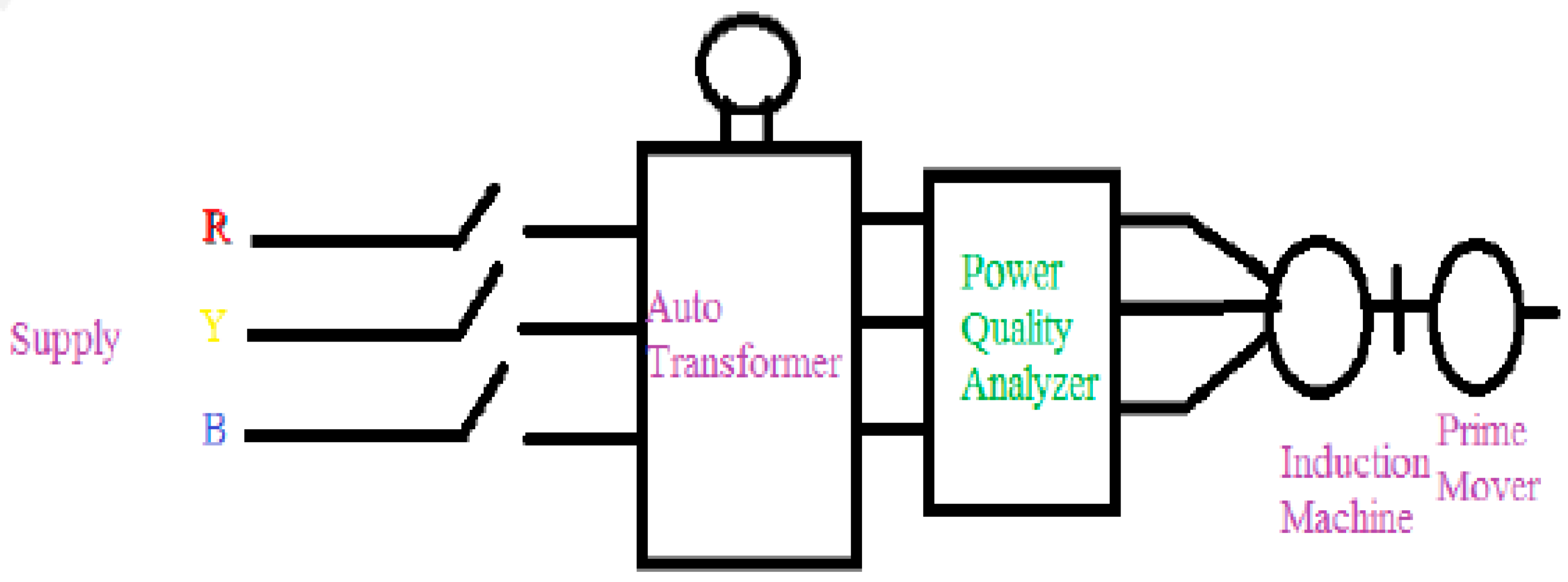
2.1. Standard Tests for Analysis of Self-Excited Induction Generator
2.2. Analytical Technique for Analysis of Self-Excited Induction Generator
2.3. Fuzzy Technique for Analysis and Determination of Capacitance to Maintain Constant Air-Gap Voltage of Self-Excited Induction Generator
- The 9 given inputs were stator-leakage reactance Xs, rotor-leakage reactance Xr, stator resistance Rs, rotor resistance Rr, core-loss resistance Rc, speed N, power factor PF, capacitance C, and load admittance Y.
- The 2 outputs were generated frequency ‘a’ and magnetizing reactance Xm. All input and output parameters are in per-unit values.
- The range and naming of input membership functions and output membership functions were extreme low (EL), very low (VL), low (L), medium (M), high (H), and very high (VH). By adjusting the range of the membership functions, more rules are formed and high rate of result accuracy can be achieved.
3. Data Reporting and Results
3.1. Specifications of Induction Machine
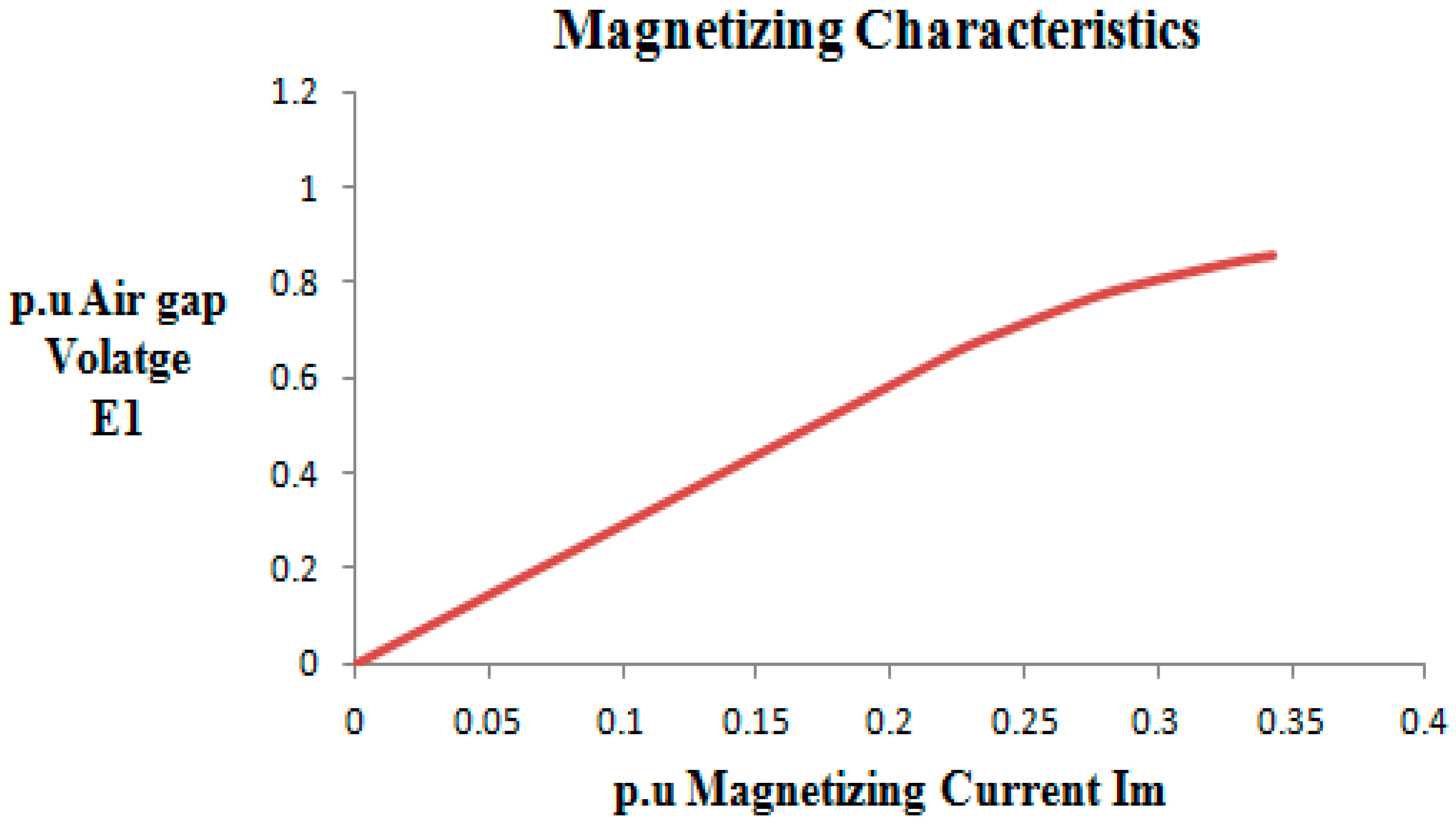
3.2. Determination of Machine Parameters and Magnetizing Characteristics with Standard Test
3.3. Determination of Machine Parameters with Analytical Technique
3.4. Determination of Machine Parameters with Fuzzy-Logic Technique
3.5. Determination of Capacitance Requirement for Maintenance of Air-Gap Voltage
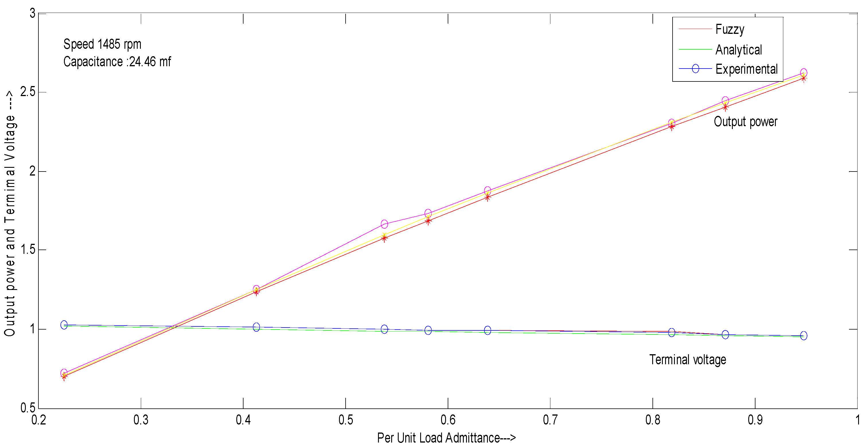
3.6. Comparison of Heuristic Methods
4. Conclusions
Author Contributions
Funding
Acknowledgments
Conflicts of Interest
Nomenclature
| Rs Xs = stator resistance and reactance | Xm = saturated magnetizing reactance |
| Rr Xr = rotor resistance and reactance | Xmu = Unsaturated magnetizing reactance |
| RL, XL = load resistance and reactance | Xc = per-phase capacitive reactance |
| Re = core loss resistance | |
| a = generated frequency | b = ratio of actual speed to synchronous speed |
| Is = stator current | Ir = rotor current |
| IL = load current | Ic = capacitive current |
| E1 = per phase air gap voltage | Z = impedance |
| Polynomial coefficients: | |
| P1 = (X1sX1rXL) | |
| P2 = (X1sX1rXL)b | |
| P3 = X1sRrRL + ReRL + X1rXc) + X1r(ReR1 + XcXL + RsRL) + XL(ReRr + ReRs + RsRr) | |
| P4 = X1sRe(X1rRL + RrXL)+ReRsXlrXL | |
| P5 = −X1s(X1rXc + ReRL)b − X1r(RsRL + ReRL + XcXL)b − (RsReXL)b | |
| P6 = −X1rRe(RsXL + X1sRL)b | |
| P7 = XcRr(Rs + RL)-XcRe(Rs + RL + Rr) | |
| P8 = (ReX1rXc(RL + Rs) − (ReRrXc(XL + X1s) − (ReRsRrRL) | |
| P9 = ReXc(Rs + RL)b | |
| P10 = XcX1rRe(RL + Rs)b | |
| Q1 = X1sXL(Re + Rr) + X1sX1rRL + X1rXL(Re + Rs) | |
| Q2 = X1sX1rXLRe | |
| Q3 = −X1s(ReXL + X1rRL)b − X1rXL(Rs + Re)b | |
| Q4 = −(X1sX1rXLRe)b | |
| Q5 = −XcRe(X1s + X1r + XL) − RLRe(Rs + Rr) − RL(X1rXc + RrRs) − Xc(RsX1r + X1sRr + XLRr) | |
| Q6 = −ReX1r(X1sXc + XcXL + RsRL) − RrRe(X1sRL + RsXL) | |
| Q7 = Re(X1rXc + X1sXc + XL + RsRl)b + XcX1r (Rs + RL)b | |
| Q8 = ReX1r(X1sXc + XcXL)b + (X1rReRLRs)b | |
| Q9 = ReXcRr(RL + Rs) |
References
- Kaur, G.; Brar, Y.S.; Kothari, D.P. Potential of Livestock Generated Biomass: Untapped Energy Source in India. Energies 2017, 10, 847. [Google Scholar] [CrossRef]
- Pillay, A.; Karthikeyan, S.P.; Kothari, D.P. Congestion management in power system: A review. Int. J. Electr. Power Energy Syst. 2015, 70, 83–90. [Google Scholar] [CrossRef]
- Bansal, R.C.; Bhatti, T.S.; Kothari, D.P. A bibliographical survey on induction generators for application of nonconventional energy systems. IEEE Trans. Energy Convers. 2003, 18, 433–439. [Google Scholar] [CrossRef]
- Khan, F.; Khan, R.; Kouzou, A. Three phase self-excited induction generator for renewable energy generation. In Proceedings of the 1st International Conference on Power Electronics and their Applications, Djelfa, Algeria, 6–7 November 2013. [Google Scholar] [CrossRef]
- Grantham, C.; Rahman, F.; Seyoum, D. A regulated self-excited induction generator for use in a remote area power supply. In Proceedings of the 6th International Conference on Electrical Machines and Drives (Conf. Publ. No. 376), Oxford, UK, 8–10 September 1993. [Google Scholar]
- Bansal, R.C.; Bhatti, T.S.; Kothari, D.P. Induction generator for isolated hybrid power system applications: A review. J. Inst. Eng. (India) 2003, 83, 262–269. [Google Scholar]
- Faisal Khan, M.; Rizwan, M. Comprehensive analytical and experimental analysis of a self excited induction generator for renewable energy applications. Int. J. Renew. Energy Res. 2015, 5, 747–756. [Google Scholar]
- Nagrath, I.J.; Kothari, D.P. Electrical Machines; Tata McGraw-Hill: New York, NY, USA, 1997. [Google Scholar]
- Bansal, R.; Bhatti, T.; Kothari, D. On some of the design aspects of wind energy conversion systems. Energy Convers. Manag. 2002, 43, 2175–2187. [Google Scholar] [CrossRef]
- Farrag, M.E.; Putrus, G.A. Analysis of the Dynamic Performance of Self-Excited Induction Generators Employed in Renewable Energy Generation. Energies 2014, 7, 278–294. [Google Scholar] [CrossRef]
- Goyal, S.K.; Palwalia, D.K. Analysis of performance parameters and estimation of optimum capacitance for asynchronous generator. Sci. Technol. Int. J. 2016, 19, 1753–1762. [Google Scholar] [CrossRef][Green Version]
- Basset, E.D.; Potter, F.M. Capacitive excitation for induction generator. AIEE Trans. (Electr. Eng.) 1935, 54, 540–545. [Google Scholar] [CrossRef]
- Hammad, A.E.; Mathur, R.M. New generalized concept for the design of thyristor phase controlled var compensator. IEEE Trans. Power Appar. Syst. 1977, 98, 219–231. [Google Scholar] [CrossRef]
- Ooi, B.T.; David, R.A. Induction generator/synchronous condenser system for wind turbine power. IEE Proc. 1979, 126, 69–74. [Google Scholar] [CrossRef]
- Singh, S.P.; Singh, B.; Jain, M.P. Performance characteristics and optimum utilization of a cage Machine as capacitor excited induction generator. IEEE Trans. Energy Convers. 1990, 5, 679–684. [Google Scholar] [CrossRef]
- Murthy, S.S. A novel self-excited self-regulated single phase Induction generator, Part 1: Basic system and theory. IEEE Trans. Energy Convers. 1993, 8, 377–382. [Google Scholar] [CrossRef]
- Bim, E.; Szajner, J.; Burian, Y. Voltage compensation of an induction generator with long shunt. IEEE Trans. Energy Convers. 1995, 10, 305–313. [Google Scholar] [CrossRef]
- Ojo, O. Performance of self-excited single-phase induction generators with shunt, short-shunt and long-shunt excitation connections. IEEE Trans. Energy Convers. 1996, 11, 477–482. [Google Scholar] [CrossRef]
- Wang, L.; Su, J.Y. Dynamic performances of an isolated self-excited induction generator under various loading conditions. IEEE Trans. Energy Convers. 1999, 14, 93–100. [Google Scholar] [CrossRef]
- Chan, T.F.; Lai, L.L. Capacitance requirements of a three-phase induction generator self-excited with a single capacitance and supplying a single-phase load. IEEE Trans. Energy Convers. 2002, 17, 90–94. [Google Scholar] [CrossRef]
- Seyoum, D.; Grantham, C.; Rahman, M.F. The dynamic characteristics of an isolated self-excited induction generator driven by a wind turbine. IEEE Trans. Ind. Appl. 2003, 39, 936–944. [Google Scholar] [CrossRef]
- Ahmed, T.; Noro, O.; Matzuo, K.; Shindo, Y.; Nakaoka, M. Minimum Excitatauion capacitance requirements for wind turbine coupled stand alone self excited induction generator with voltage regulation based on SVC. In Proceedings of the 25th International Telecommunications Energy Conference, Yokohama, Japan, 23–23 October 2003. [Google Scholar]
- Singh, G.K.; Kumar, A.S.; Saini, R.P. Selection of capacitor for the self-excited six-phase induction generator. In Proceedings of the International Conference on Power Systems, Kharagpur, India, 27–29 December 2009. [Google Scholar]
- Khela, R.S.; Sandhu, K.S. ANN model for estimation of capacitance requirements to maintain constant air gap voltage of self excited induction generator with variable load. Int. J. Comput. Sci. Technol. 2011, 2, 53–57. [Google Scholar]
- Haque, M.H.; Maswood, A.I. Determination of excitation capacitance of a three-phase self-excited induction generator. In Proceedings of the IEEE Power and Energy Society General Meeting, San Diego, CA, USA, 22–26 July 2012. [Google Scholar]
- Kumar, S.; Pradhan, S.; Sahu, R.N. Excitation capacitance requirement of three phase self excited induction generator for wind mill applications. In Proceedings of the International Conference on Energy Efficient Technologies for Sustainability, Nagercoil, India, 10–12 April 2013. [Google Scholar]
- Abbou, A.; Barara, M.; Ouchatti, A.; Akherraz, M.; Mahmoudi, H. Capacitance required analysis for self excited induction generator. J. Theor. Appl. Inf. Technol. 2013, 55, 382–389. [Google Scholar]
- Khan, M.F.; Khan, M.R. Evaluation of excitation capacitance for a single-phase two winding self excited induction generator. In Proceedings of the IEEE International Conference on Power Electronics, Drives and Energy Systems (PEDES), Mumbai, India, 16–19 December 2014. [Google Scholar]
- Mohanty, A.K.; Yadav, K.B. Estimation of excitation capacitance requirement of an isolated multi-phase induction generator for power generation. Int. J. Power Electron. Drive Syst. (IJPEDS) 2016, 7, 561–567. [Google Scholar] [CrossRef][Green Version]
- Mhamdi, T.; Barhoumi, A.; Sabita, L. Stand-alone self excited induction generator driven by wind turbine. Alex. Eng. J. 2017. [Google Scholar] [CrossRef]
- Sakkoury, K.S.; Emara, S.; Ahmed, M.K. Analysis of wind driven self-excited induction generator supplying isolated DC loads. J. Electr. Syst. Inf. Technol. 2017, 4, 257–268. [Google Scholar] [CrossRef]
- Quazene, L.; McPherson, G. Analysis of an isolated induction generator. IEEE Trans. Power Appl. Syst. 1983, 102, 2793–2798. [Google Scholar] [CrossRef]
- Al-Bahrani, A.H.; Malik, N.H. Steady-state analysis and performance characteristic of a 3-phase induction generator self-excited with a single capacitor. IEEE Trans. Energy Convers. 1990, 5, 725–732. [Google Scholar] [CrossRef]
- Murthy, S.S.; Malik, O.P.; Tandon, A.K. Analysis of self excited induction generator. IEE Proc. C (Gener. Transm. Distrib.) 1982, 129, 260–265. [Google Scholar] [CrossRef]
- Narayanan, S.S.Y.; Johnny, V.J. Contribution to the steady state analysis of wind-turbine driver self-excited induction generator. IEEE Trans. Energy Convers. 1986, 1, 169–176. [Google Scholar] [CrossRef]
- Raina, G.; Malik, O.P. Wind energy conversion using a self-excited induction generator. IEEE Trans. Power Appar. Syst. 1983, 12, 3933–3936. [Google Scholar] [CrossRef]
- Singh, S.P.; Singh, B.; Jain, M.P. Steady state analysis of self excited pole changing induction generator. J. Inst. Eng. 1992, 73, 137–144. [Google Scholar]
- Krause, P.C.; Thomas, C.H. Simulation of symmetrical induction machinery. IEEE Trans. Power Appar. 1965, 11, 1038–1053. [Google Scholar] [CrossRef]
- Tandon, A.K.; Murthy, S.S.; Berg, G.J. Steady state analysis of capacitor self-excited induction generators. IEEE Trans. Power Appar. Syst. 1984, 3, 612–618. [Google Scholar] [CrossRef]
- Bansal, R.C. Automatic Reactive Power Control of Autonomous Hybrid Power Systems. Ph.D. Thesis, Indian Institute of Technology, Delhi, India, 2002. [Google Scholar]
- Bansal, R.C.; Bhatti, T.S.; Kothari, D.P. A novel mathematical modelling of induction generator for reactive power control of isolated hybrid power systems. Int. J. Model. Simul. 2004, 24, 1–7. [Google Scholar] [CrossRef]
- Sandhu, K.S.; Jain, S.K. Operational Aspects of SEIG Using a New Model. Electr. Mach. Power Syst. 1999, 27, 169–180. [Google Scholar] [CrossRef]
- Khan, M.F.; Khan, M.R.; Iqbal, A. Performance Analysis of Shunt, Short Shunt and Long Shunt Self excited induction generator: Analysis of Shunt, Short Shunt and Long Shunt SEIG. In Proceedings of the IEEE International Conference on Power Electronics, Drives and Energy Systems (PEDES), Bengaluru, India, 16–19 December 2012. [Google Scholar]
- Chan, T.F. Capacitive requirements of self-excited induction generators. IEEE Trans. Energy Convers. 1993, 8, 304–311. [Google Scholar] [CrossRef]
- Joshi, D.; Sandhu, K.S.; Soni, M.K. Performance analysis of self excited induction generator using artificial neural network. Iran. J. Electr. Comput. Eng. 2006, 5, 57–62. [Google Scholar]
- Enany, M.A. Steady State Modeling and ANIFS based Analysis of self excited induction generator. Wind Eng. 2014, 38, 229–238. [Google Scholar] [CrossRef]


| Type of Machine | Power Rating (HP) | Voltage Rating (volt) | Current Rating (Amp) | Speed (RPM) | No. of Poles | Type of Connection |
|---|---|---|---|---|---|---|
| Three-Phase Induction Machine | 5.0 | 415 | 7.60 | 1500 | 4 | Delta |
| Voltage (Volt) | Current (Amp) | Power (VA) | Frequency (Hz) | Speed (RPM) | Impedance (Ohm) | Admittance (Mho) | Capacitance (μF) |
|---|---|---|---|---|---|---|---|
| 415 | 4.33 | 1797 | 50 | 1500 | 95.84 | 0.010 | 25.46 |
| Stator Resistance (p.u) | Rotor Resistance (p.u) | Stator-Leakage Reactance (p.u) | Rotor Leakage Reactance (p.u) | Core-Branch Resistance (p.u) | Magnetizing Reactance Unsaturated (p.u) |
|---|---|---|---|---|---|
| 0.061 | 0.0437 | 0.097 | 0.097 | 32.53 | 2.973 |
| Load Admittance (p.u) | Magnetizing Reactance (p.u) Analytical | Magnetizing Reactance (p.u) Fuzzy | Generated Frequency 9 (p.u) Analytical | Generated Frequency (p.u) Fuzzy |
|---|---|---|---|---|
| 0.225 | 1.232 | 1.227 | 0.975 | 0.976 |
| 0.538 | 1.434 | 1.430 | 0.961 | 0.962 |
| 0.6389 | 1.526 | 1.525 | 0.957 | 0.956 |
| 0.871 | 1.817 | 1.827 | 0.947 | 0.947 |
| Speed (p.u.) | Magnetizing Reactance (p.u.) Analytical | Magnetizing Reactance (p.u.) Fuzzy | Generated Frequency (p.u.) Analytical | Generated Frequency (p.u.) Fuzzy |
|---|---|---|---|---|
| 0.923 | 1.969 | 1.9698 | 0.903 | 0.903 |
| 0.953 | 1.844 | 1.846 | 0.932 | 0.932 |
| 1.014 | 1.623 | 1.621 | 0.991 | 0.992 |
| 1.071 | 1.448 | 1.443 | 1.047 | 1.047 |
| Capacitance (p.u.) | Magnetizing Reactance (p.u.) Analytical | Magnetizing Reactance (p.u.) Fuzzy | Generated Frequency (p.u.) Analytical | Generated Frequency (p.u.)n Fuzzy |
|---|---|---|---|---|
| 0.608 | 2.200 | 2.204 | 0.997 | 0.997 |
| 0.665 | 1.985 | 1.986 | 0.997 | 0.997 |
| 0.764 | 1.698 | 1.696 | 0.996 | 0.996 |
| 0.830 | 1.549 | 1.547 | 0.995 | 0.996 |
| Load Admittance (p.u) | Air-Gap Voltage (p.u) | Additional Capacitance (p.u) Fuzzy | Additional Capacitance (p.u) Analytical | Additional Capacitance (p.u) Standard Test |
|---|---|---|---|---|
| 0.225 | 1.0 | 0.581 | 0.580 | 0.590 |
| 0.413 | 1.0 | 0.633 | 0.632 | 0.651 |
| 0.538 | 1.0 | 0.694 | 0.693 | 0.719 |
| 0.580 | 1.0 | 0.694 | 0.693 | 0.719 |
| 0.638 | 1.0 | 0.719 | 0.718 | 0.743 |
| 0.819 | 1.0 | 0.805 | 0.806 | 0.832 |
| 0.871 | 1.0 | 0.838 | 0.835 | 0.855 |
| 0.948 | 1.0 | 0.882 | 0.881 | 0.895 |
| Load Admittance (p.u.) | Terminal Voltage (p.u.) Fuzzy | Terminal Voltage (p.u.) Analytical | Terminal Voltage (p.u.) Standard Test | Output Power (p.u.) Fuzzy | Output Power (p.u.) Analytical | Output Power (p.u.) Standard Test |
|---|---|---|---|---|---|---|
| 0.225 | 1.031 | 1.017 | 1.028 | 0.718 | 0.698 | 0.709 |
| 0.413 | 1.015 | 0.998 | 1.014 | 1.251 | 1.236 | 1.249 |
| 0.538 | 0.996 | 0.987 | 0.997 | 1.665 | 1.574 | 1.600 |
| 0.580 | 0.995 | 0.983 | 0.995 | 1.732 | 1.686 | 1.710 |
| 0.638 | 0.993 | 0.978 | 0.992 | 1.875 | 1.836 | 1.861 |
| 0.819 | 0.987 | 0.964 | 0.980 | 2.305 | 2.283 | 2.308 |
| 0.871 | 0.966 | 0.959 | 0.966 | 2.443 | 2.408 | 2.431 |
| 0.948 | 0.956 | 0.954 | 0.956 | 2.621 | 2.590 | 2.610 |
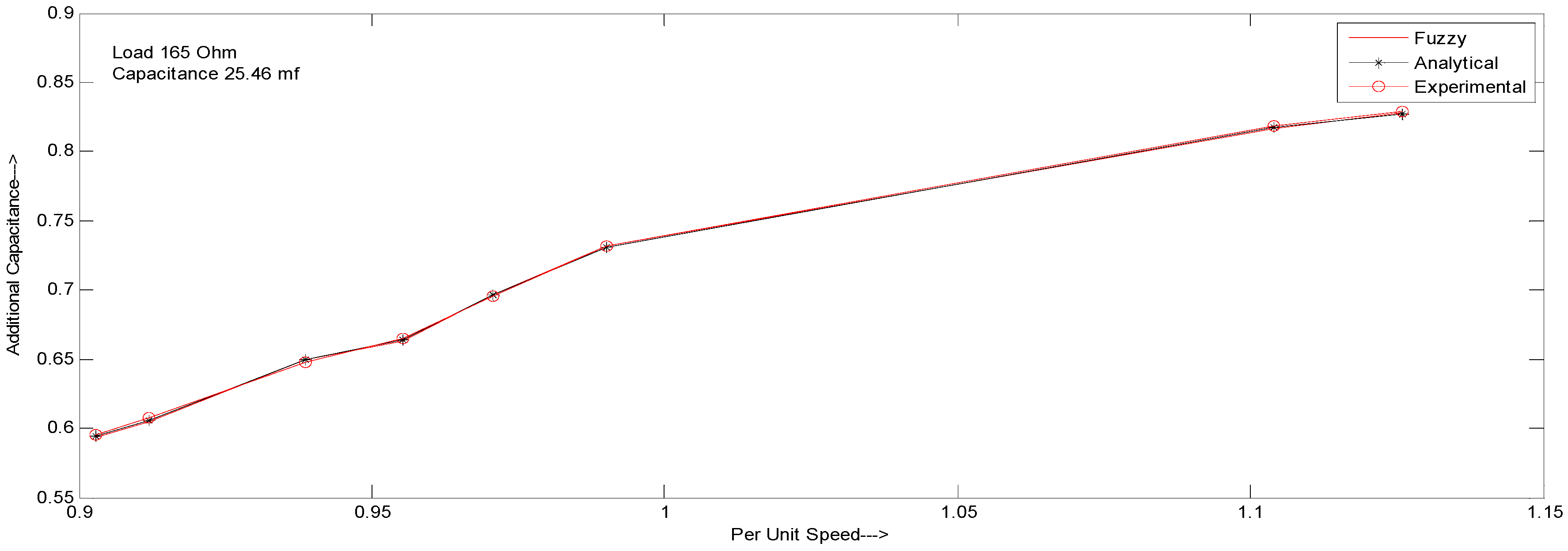
| Speed (p.u) | Air gap Voltage (p.u.) | Additional Capacitance (p.u.) Fuzzy | Additional Capacitance (p.u.) Analytical | Additional Capacitance (p.u.) Standard Test |
|---|---|---|---|---|
| 0.903 | 1.0 | 0.583 | 0.583 | 0.583 |
| 0.912 | 1.0 | 0.644 | 0.643 | 0.634 |
| 0.938 | 1.0 | 0.649 | 0.648 | 0.648 |
| 0.955 | 1.0 | 0.703 | 0.703 | 0.704 |
| 0.970 | 1.0 | 0.726 | 0.726 | 0.725 |
| 0.990 | 1.0 | 0.791 | 0.790 | 0.791 |
| 1.104 | 1.0 | 0.837 | 0.837 | 0.837 |
| 1.036 | 1.0 | 0.887 | 0.887 | 0.888 |
| (18) |
| Speed (p.u) | Terminal Voltage (p.u) Fuzzy | Terminal Voltage (p.u) Analytical | Terminal Voltage (p.u) Standard Test | Output Power (p.u) Fuzzy | Output Power (p.u) Analytical | Output Power (p.u) Standard Test |
|---|---|---|---|---|---|---|
| 0.903 | 0.792 | 0.792 | 0.793 | 1.0078 | 0.9861 | 0.9917 |
| 0.912 | 0.792 | 0.792 | 0.795 | 1.0373 | 1.0189 | 1.0234 |
| 0.938 | 0.818 | 0.818 | 0.815 | 1.1436 | 1.123 | 1.1235 |
| 0.953 | 0.849 | 0.849 | 0.845 | 1.3083 | 1.2972 | 1.2944 |
| 0.970 | 0.873 | 0.873 | 0.876 | 1.4263 | 1.4162 | 1.4124 |
| 0.990 | 0.889 | 0.889 | 0.887 | 1.6021 | 1.5849 | 1.581 |
| 1.104 | 0.905 | 0.901 | 0.905 | 1.7323 | 1.7173 | 1.7145 |
| 1.036 | 0.906 | 0.905 | 0.903 | 1.8703 | 1.857 | 1.8575 |
© 2018 by the authors. Licensee MDPI, Basel, Switzerland. This article is an open access article distributed under the terms and conditions of the Creative Commons Attribution (CC BY) license (http://creativecommons.org/licenses/by/4.0/).
Share and Cite
Sharma, A.; Kaur, G. Assessment of Capacitance for Self-Excited Induction Generator in Sustaining Constant Air-Gap Voltage under Variable Speed and Load. Energies 2018, 11, 2509. https://doi.org/10.3390/en11102509
Sharma A, Kaur G. Assessment of Capacitance for Self-Excited Induction Generator in Sustaining Constant Air-Gap Voltage under Variable Speed and Load. Energies. 2018; 11(10):2509. https://doi.org/10.3390/en11102509
Chicago/Turabian StyleSharma, Ashish, and Gagandeep Kaur. 2018. "Assessment of Capacitance for Self-Excited Induction Generator in Sustaining Constant Air-Gap Voltage under Variable Speed and Load" Energies 11, no. 10: 2509. https://doi.org/10.3390/en11102509
APA StyleSharma, A., & Kaur, G. (2018). Assessment of Capacitance for Self-Excited Induction Generator in Sustaining Constant Air-Gap Voltage under Variable Speed and Load. Energies, 11(10), 2509. https://doi.org/10.3390/en11102509