Simulation and Empirical Studies of the Commercial SI Engine Performance and Its Emission Levels When Running on a CNG and Hydrogen Blend

Abstract
:1. Introduction
2. CFD Simulation
2.1. Studied Geometry
2.2. Mathematical Formulation
2.3. Turbulence
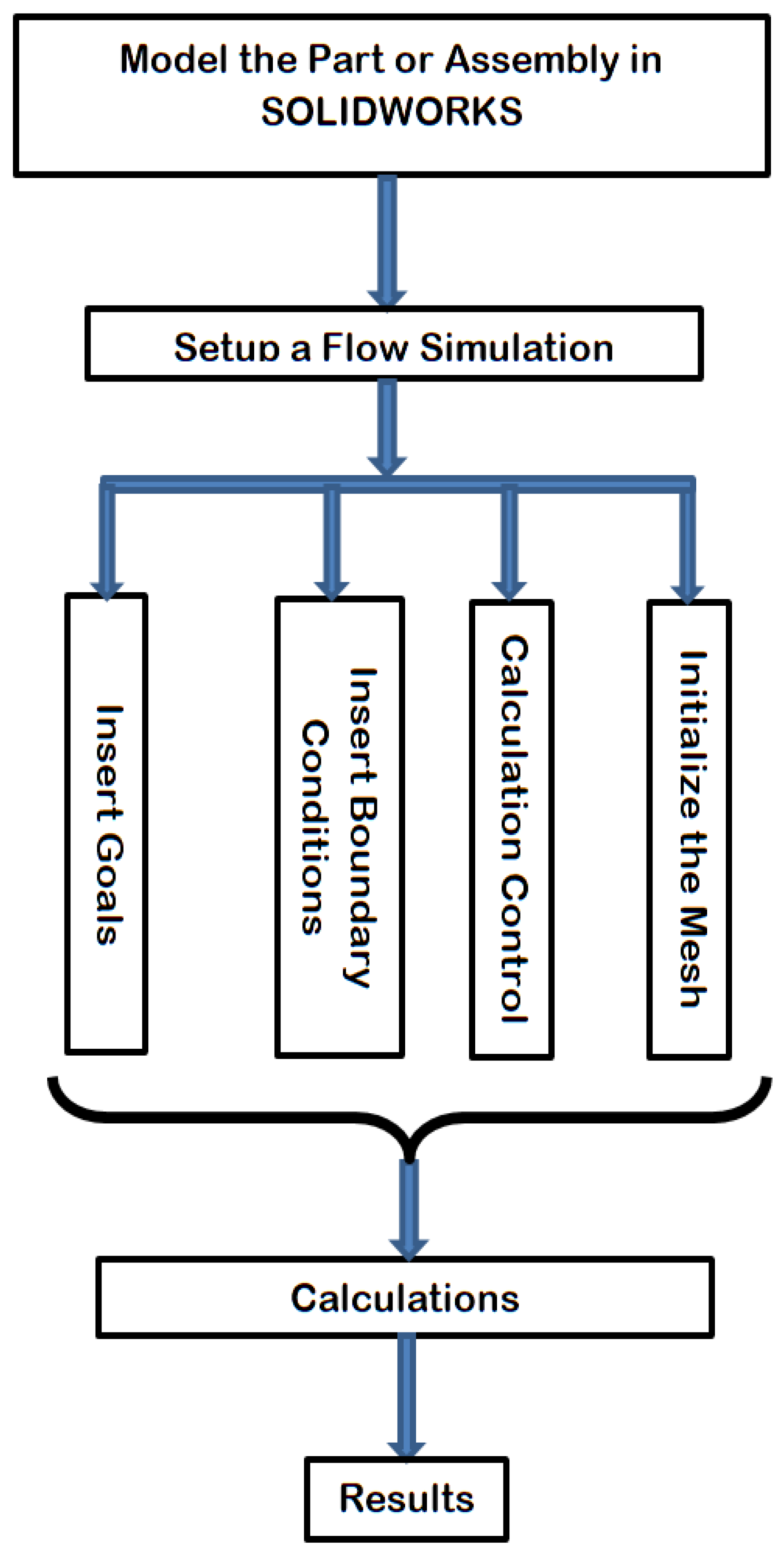
2.4. Computational Setup
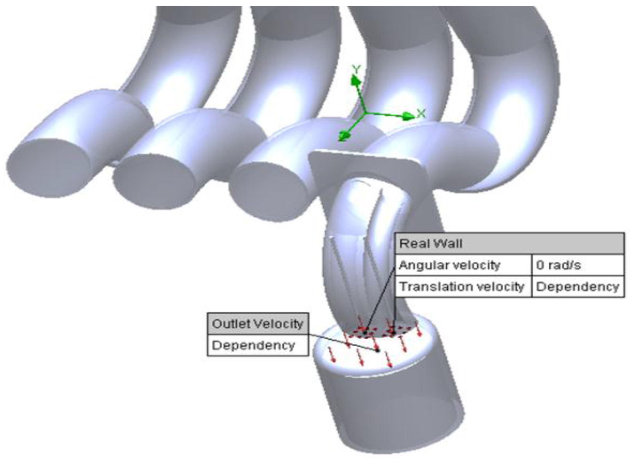
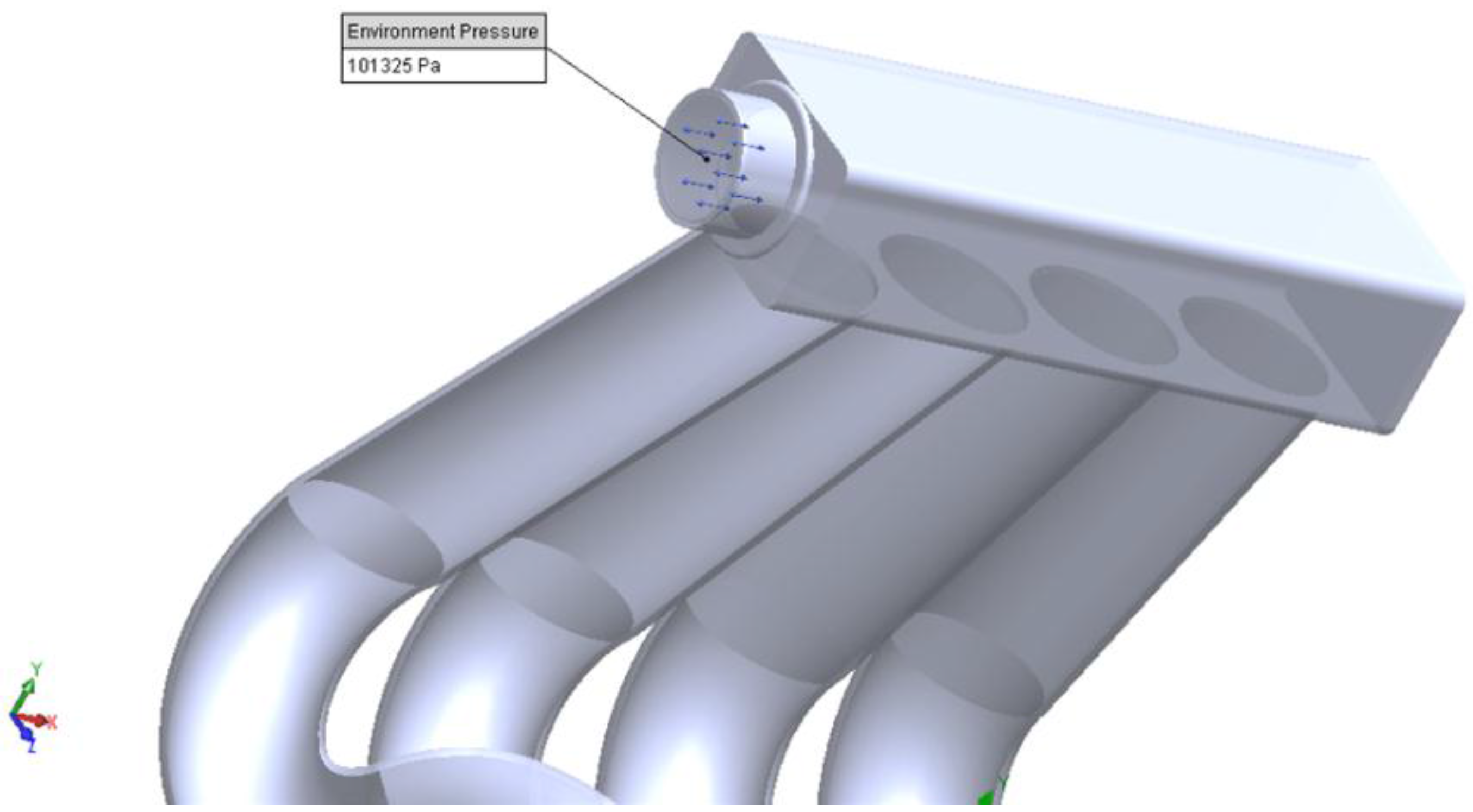
2.4.1. Boundary Conditions
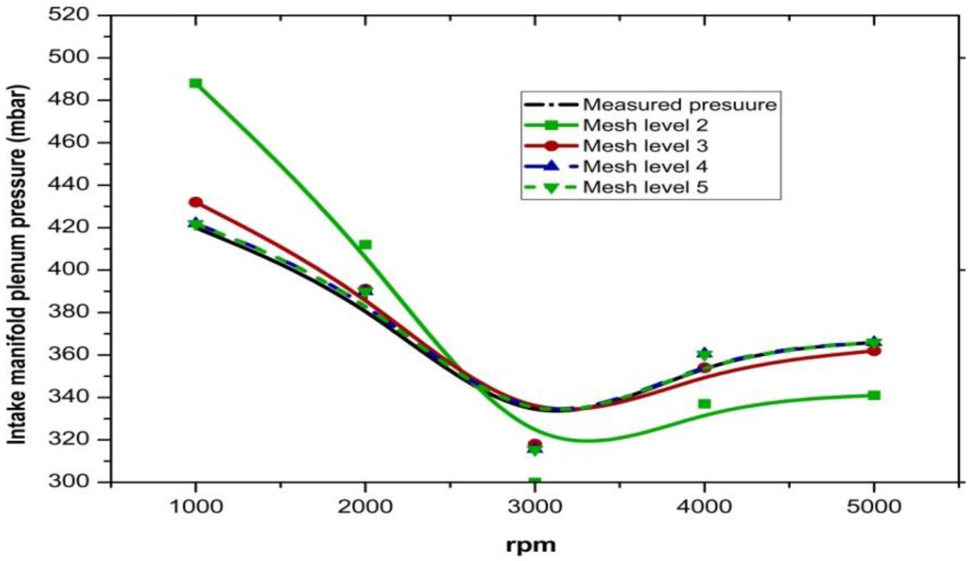
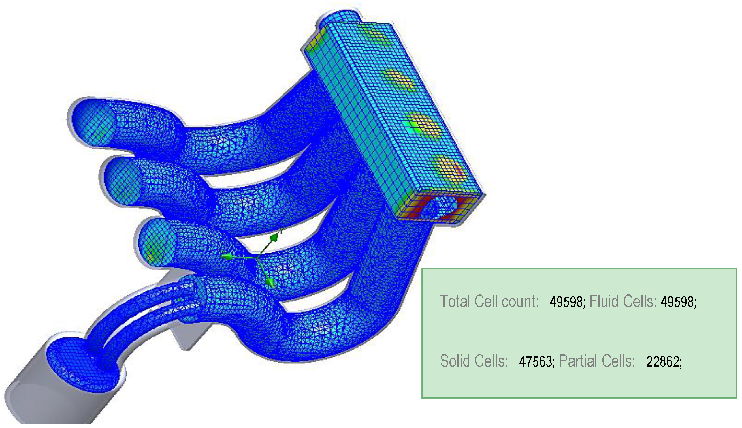
2.4.2. Mesh Settings
3. Experimental Study
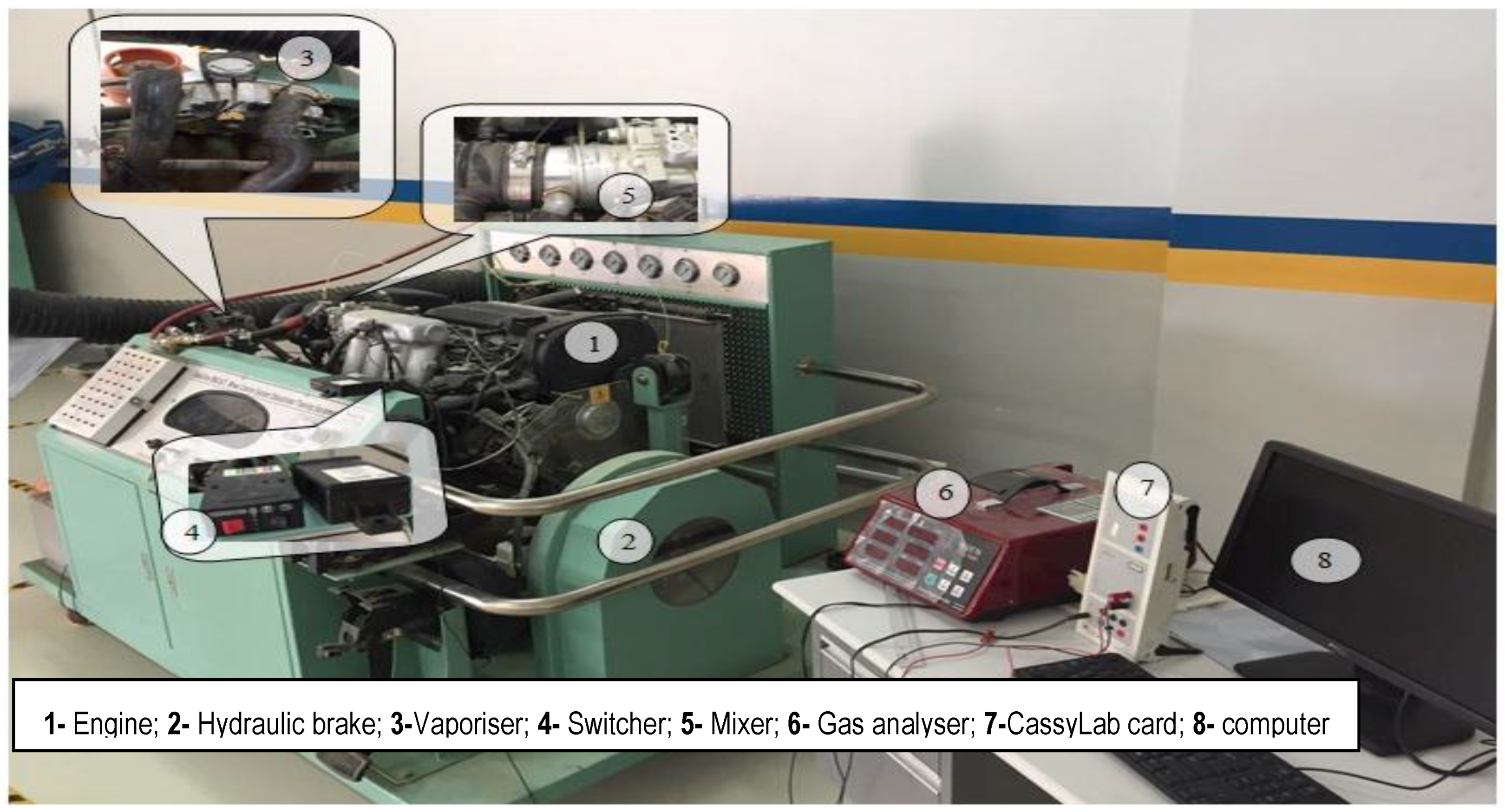
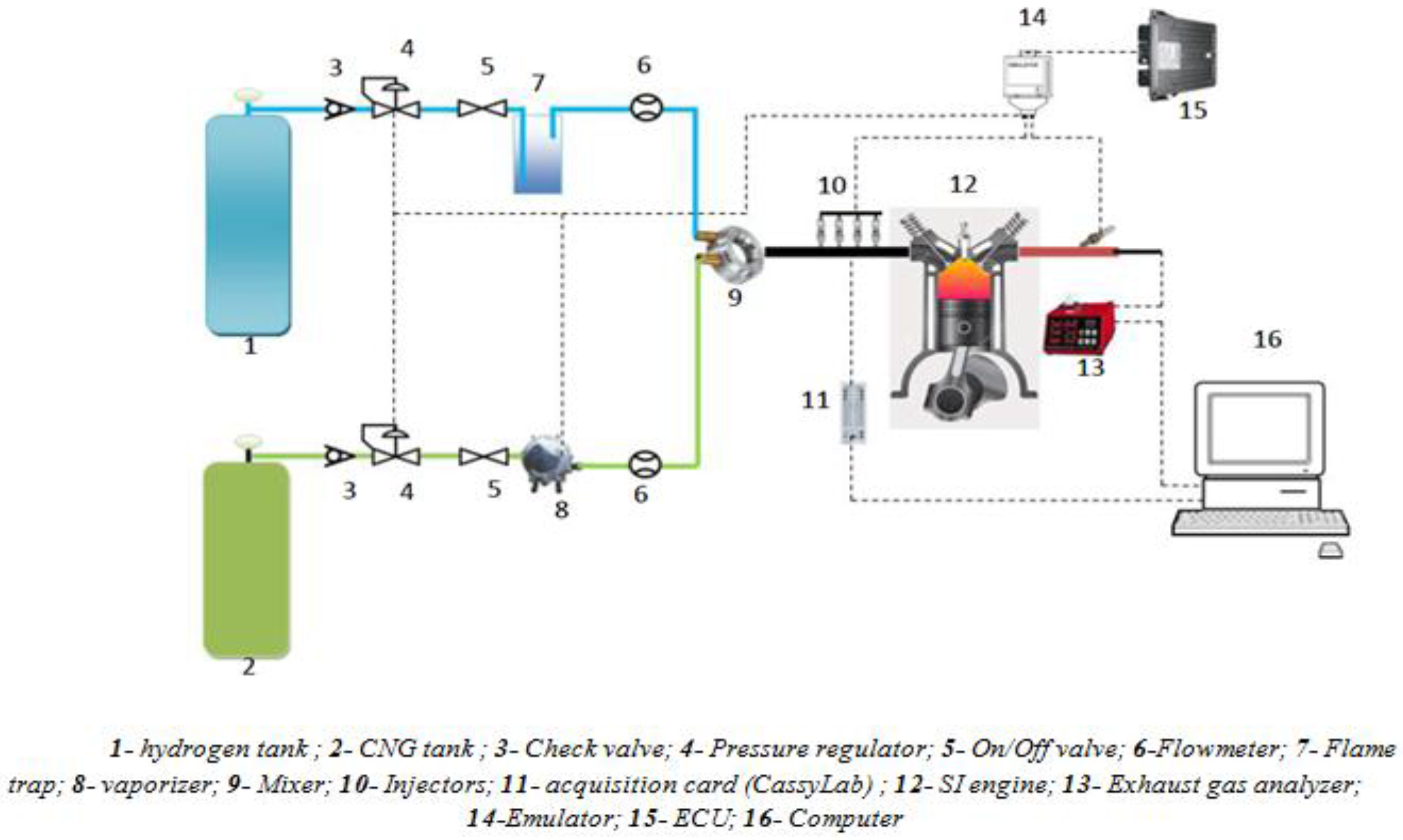
3.1. Experimental Apparatus
3.2. Estimation of Uncertainty and Error
4. Results and Discussion
4.1. CFD Results and Discussion
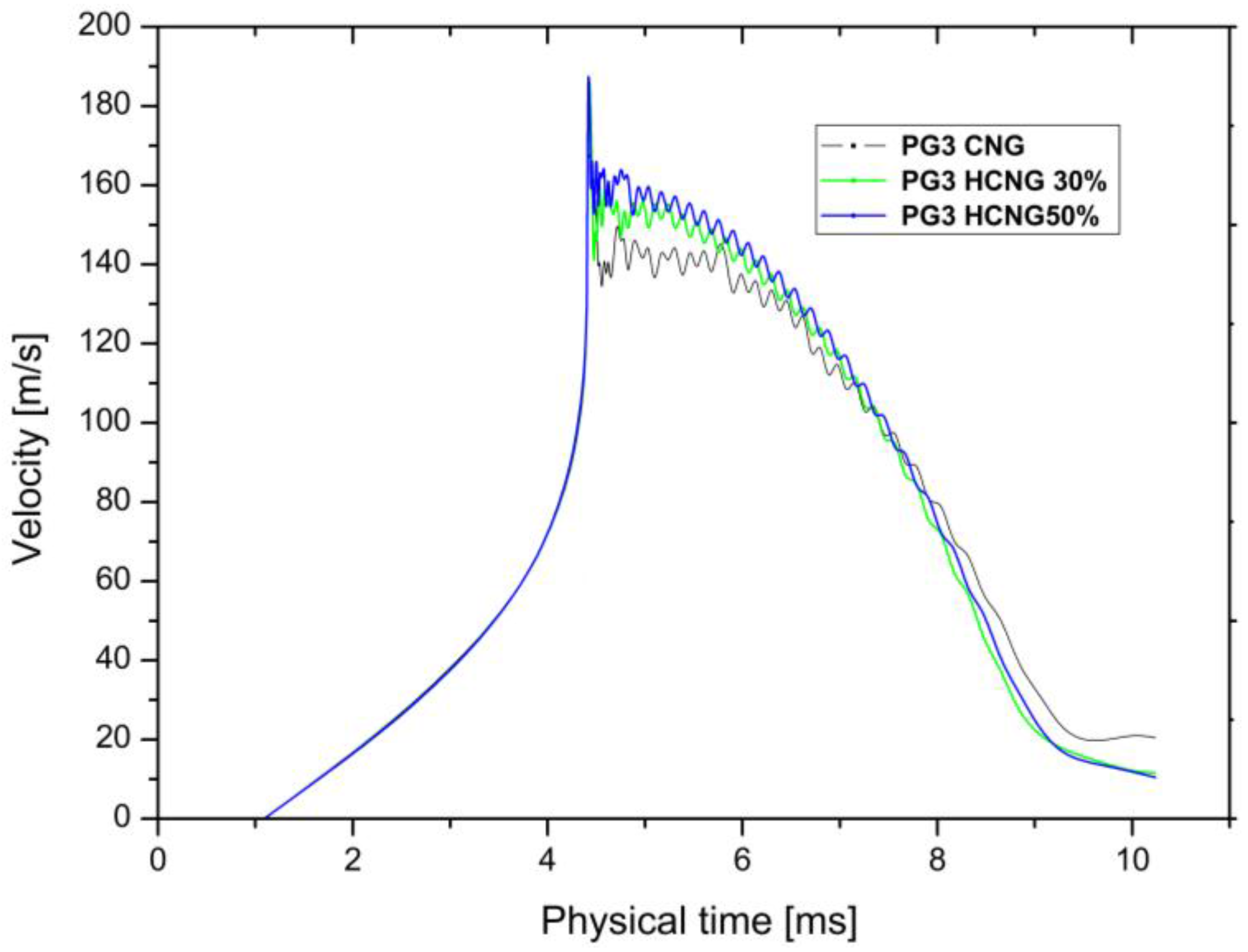
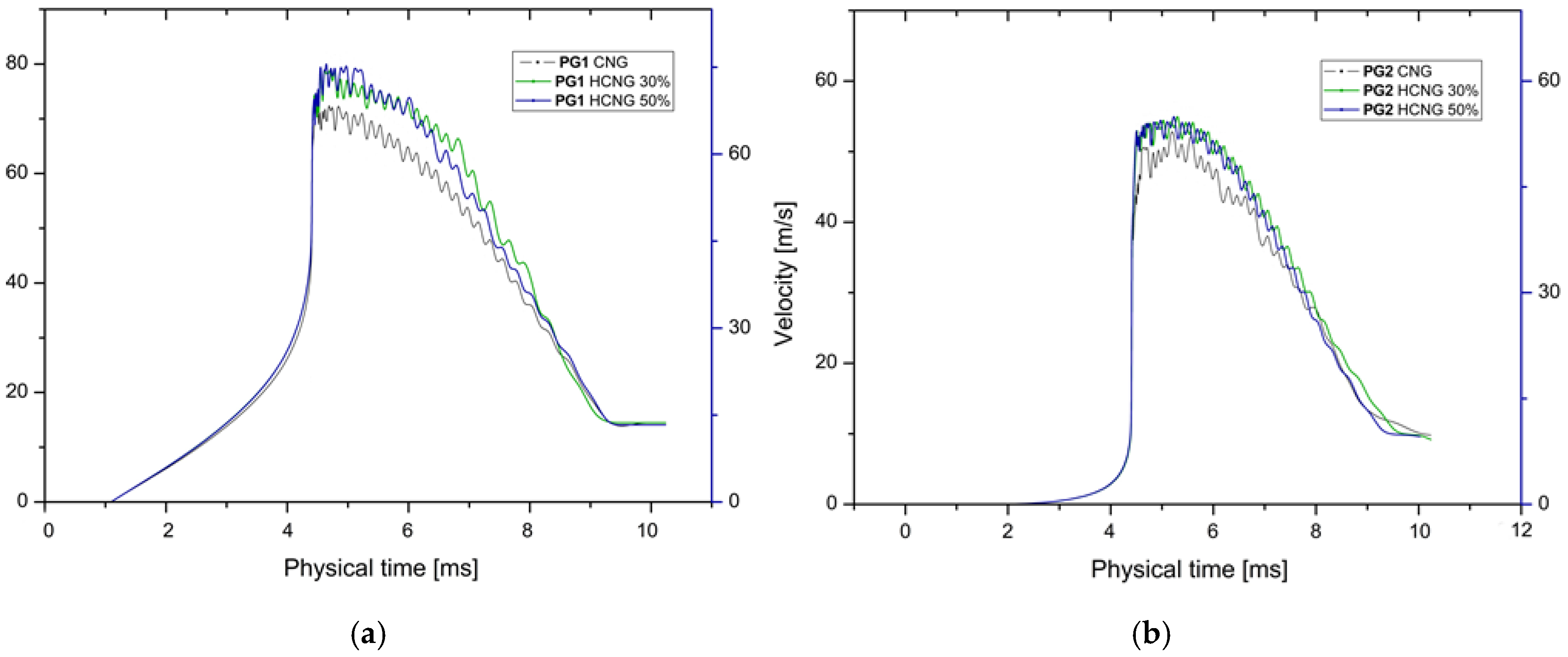
4.1.1. Effect of Hydrogen Ratio on In-Cylinder Flow
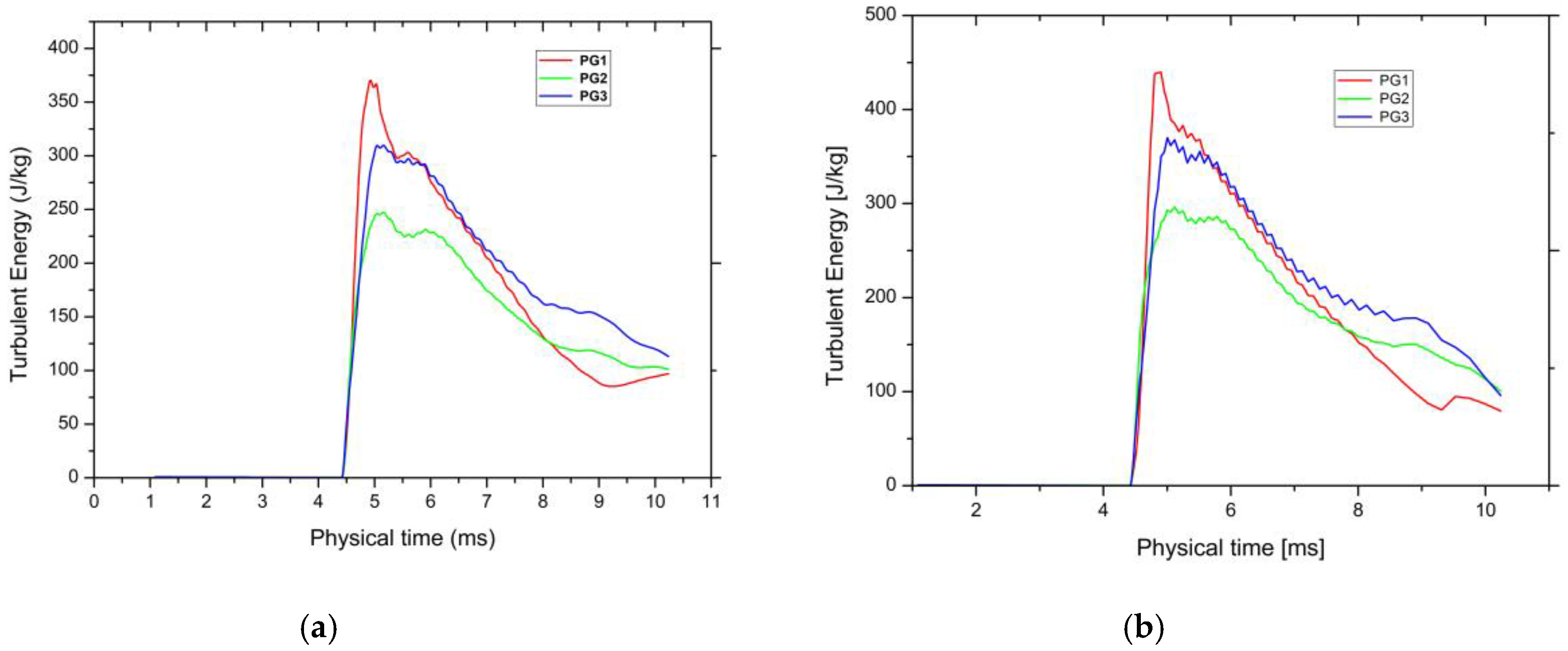
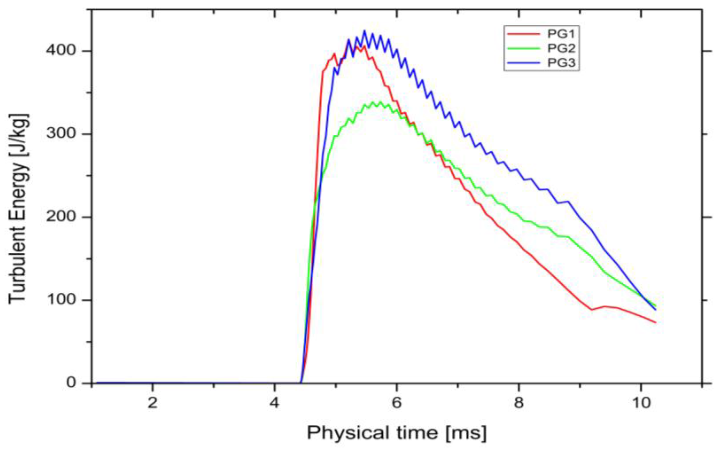
4.1.2. Effect of Hydrogen Ratio on Turbulent Energy
4.2. Experimental Results and Discussion
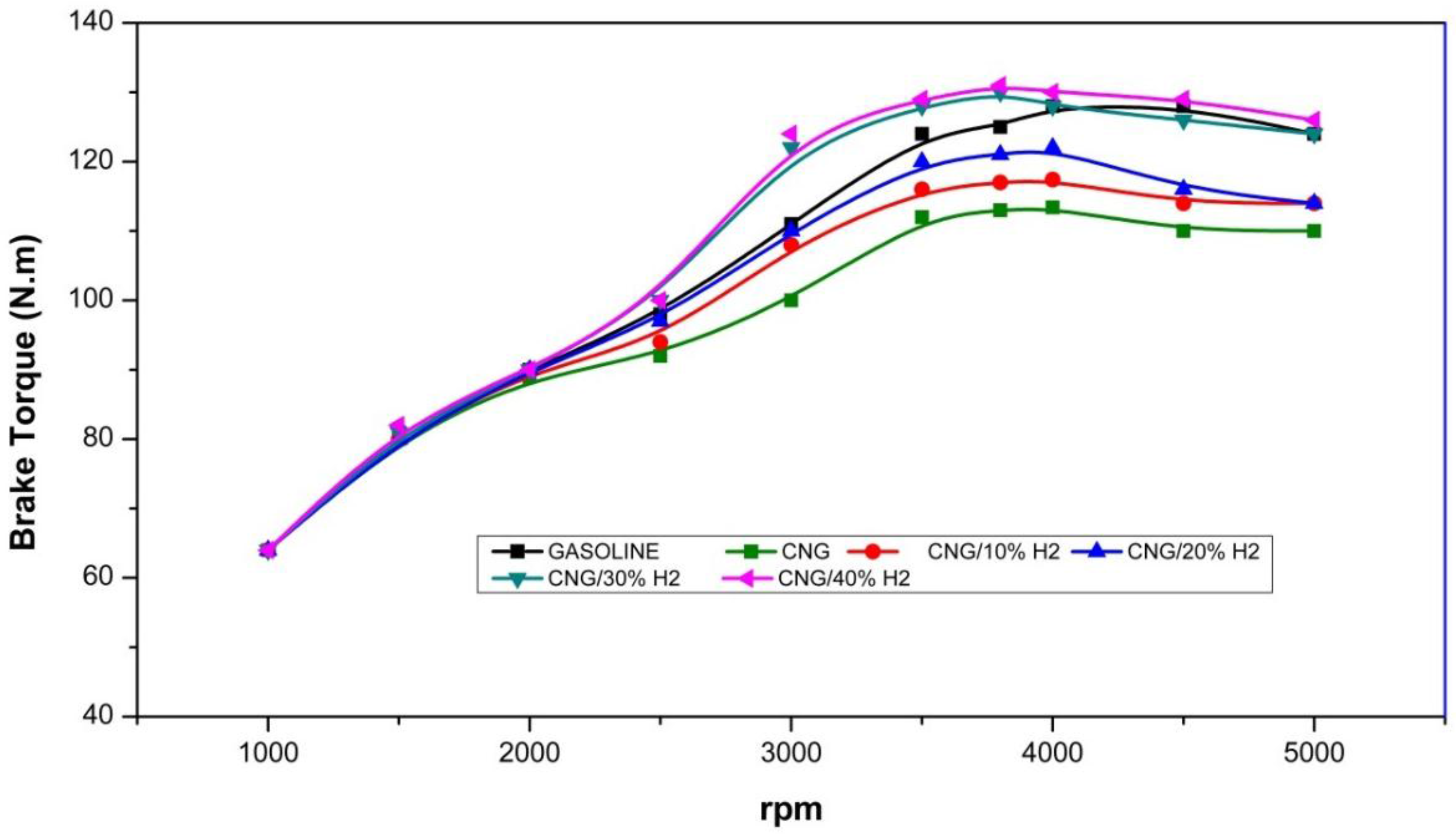
4.2.1. Effect of Hydrogen Fraction on Performance
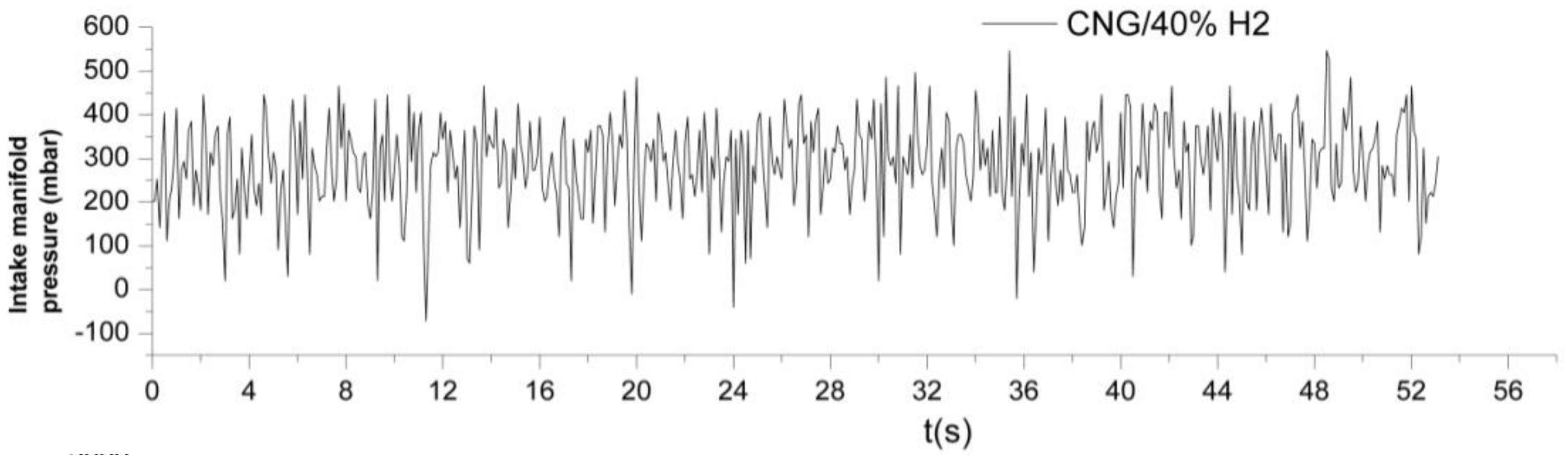
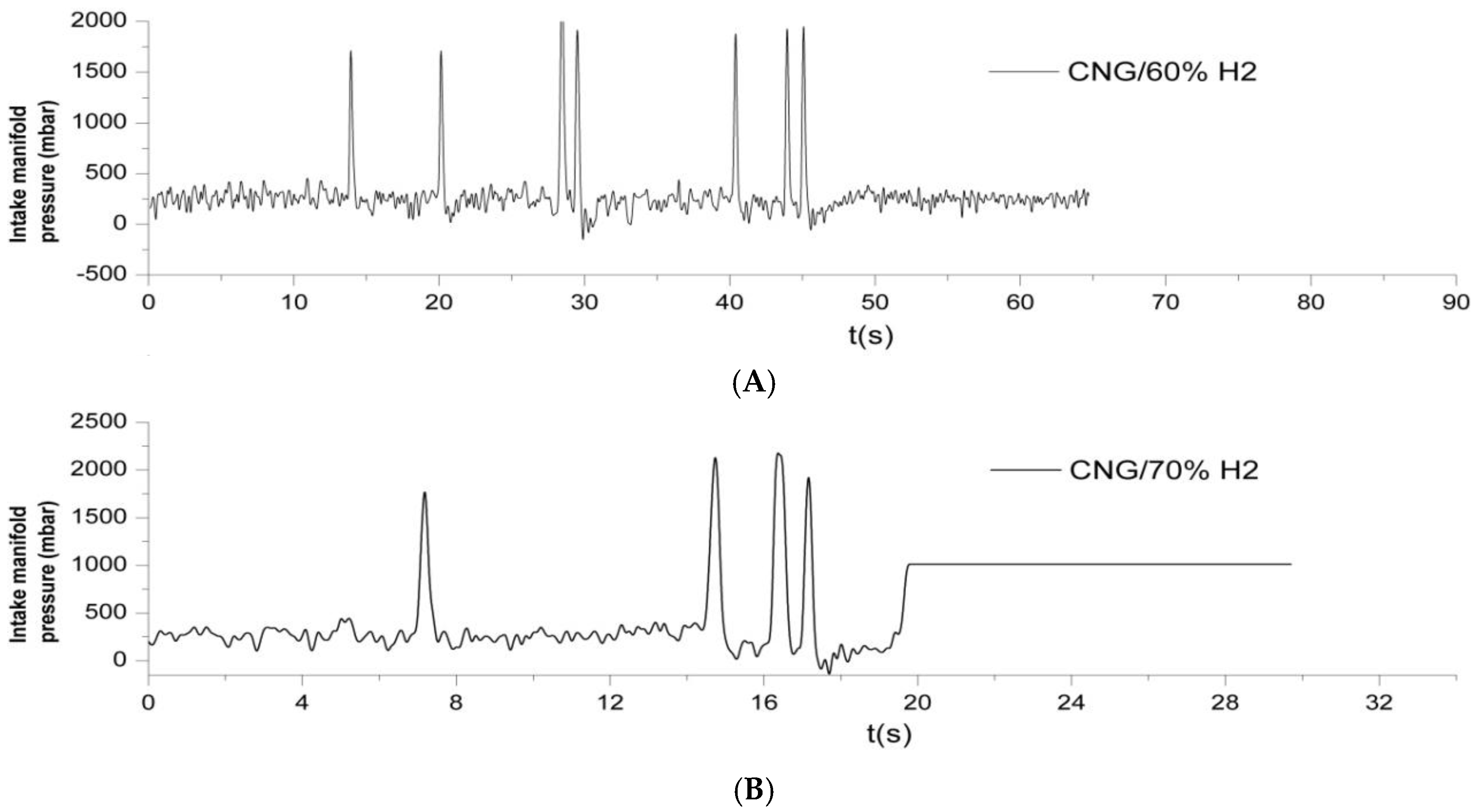
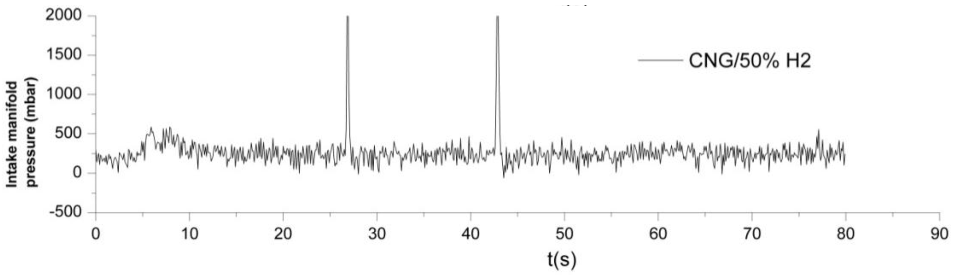
4.2.2. Limited Use of Hydrogen Ratio via External Mixture
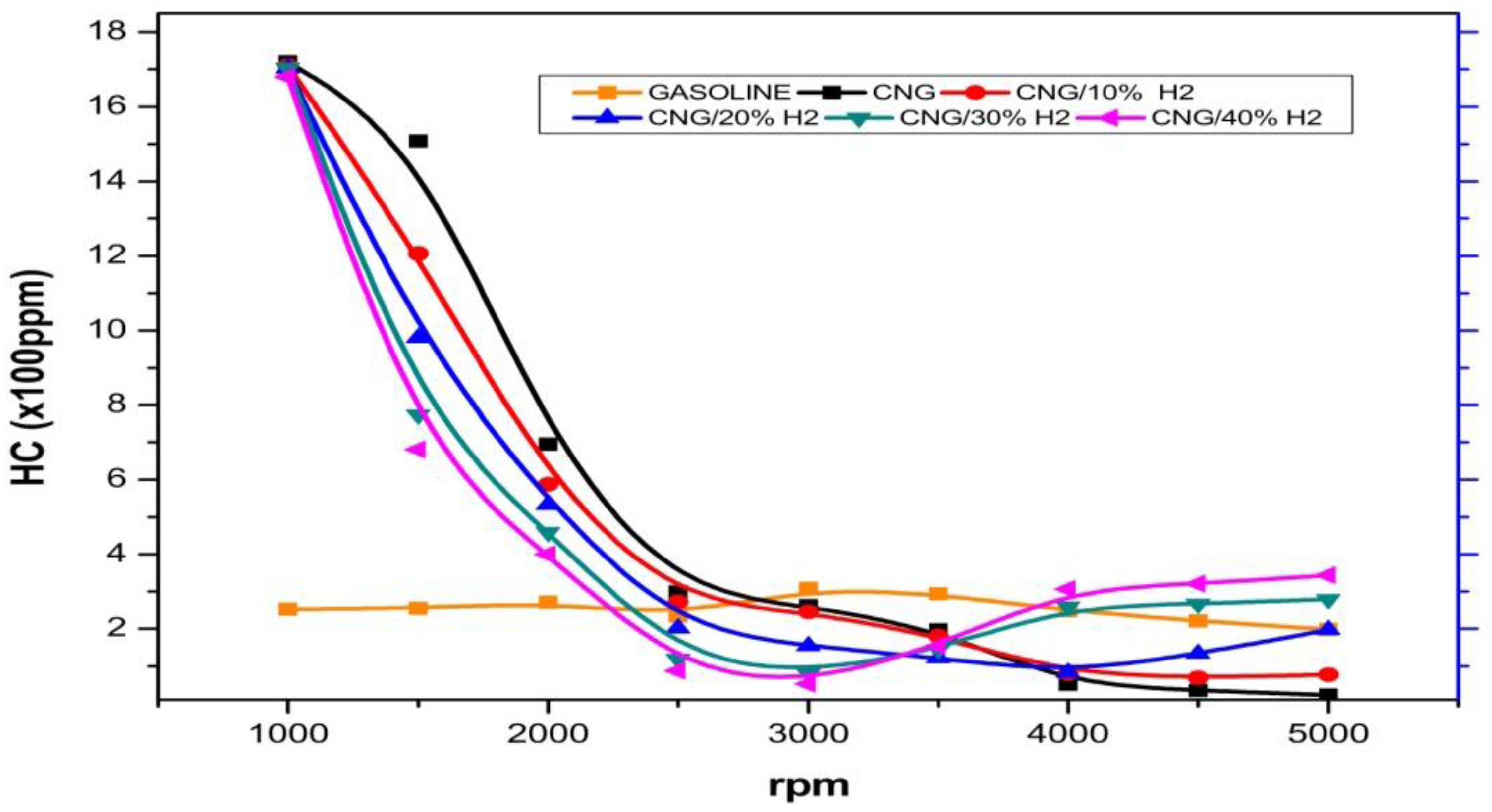
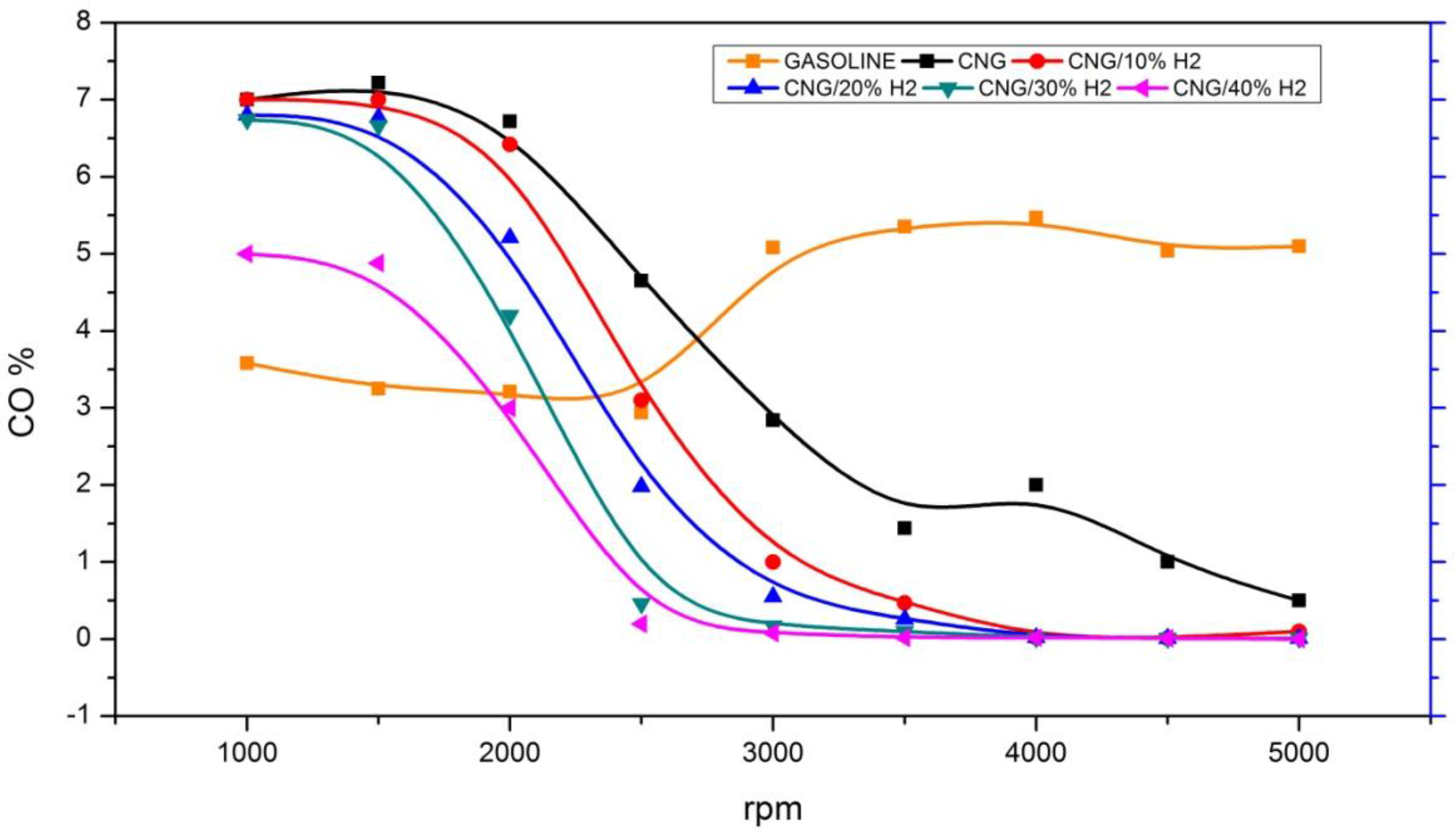
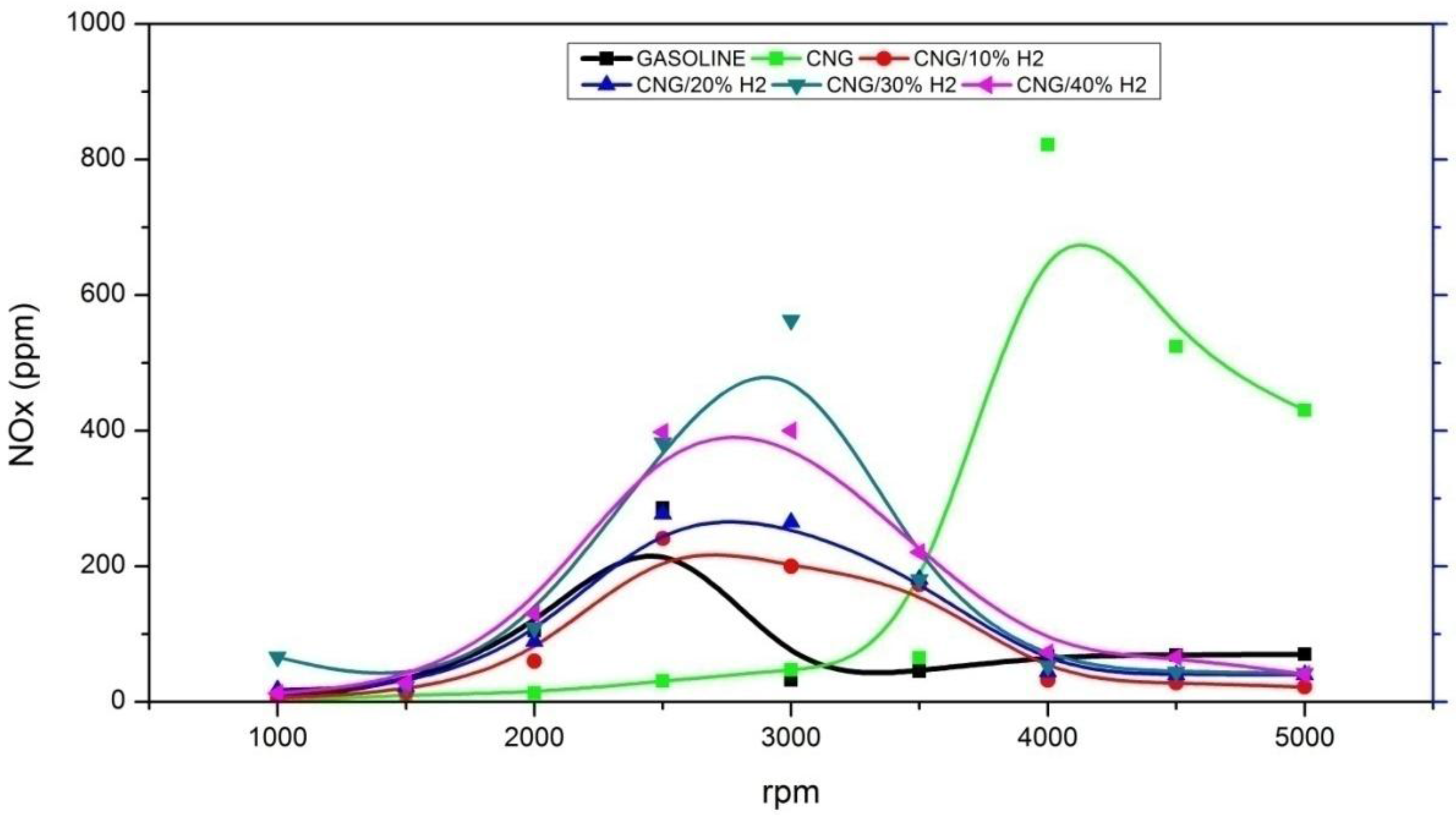
4.2.3. Emission Parameters
5. Conclusions
Acknowledgments
Author Contributions
Conflicts of Interest
References
- Cripp, H. Energy and the Environment. Available online: http://eco.gn.apc.org/pubs/energyandenvironment.html (accessed on 10 August 2007).
- Pablo-Romero, M.D.P.; De Jesús, J. Economic growth and energy consumption: The Energy-Environmental Kuznets Curve for Latin America and the Caribbean. Renew. Sustain. Energy Rev. 2016, 60, 1343–1350. [Google Scholar] [CrossRef]
- Bp Global. BP Statistical Review of World Energy; Bp Global: London, UK, June 2017. [Google Scholar]
- Muradov, N.Z.; Veziroglu, T.N. Green path from fossil-based to hydrogen economy: An overview of carbon-neutral technologies. Int. J. Hydrog. Energy 2008, 33, 6804–6839. [Google Scholar] [CrossRef]
- Jean, T.R.A.P.Y. Moteur à Allumage Commandé. Available online: https://www.techniques-ingenieur.fr/base-documentaire/mecanique-th7/technologie-des-moteurs-thermiques-42165210/moteur-a-allumage-comma-nde-bm2540/ (accessed on 19 April 2010).
- Verhelst, S.; Wallner, T. Hydrogen-fueled internal combustion engines. Prog. Energy Combust. Sci. 2009, 35, 490–527. [Google Scholar] [CrossRef]
- Kacem, S.H.; Jemni, M.A.; Driss, Z.; Abid, M.S. The effect of H2 enrichment on in-cylinder flow behavior, engine performances and exhaust emissions: Case of LPG-hydrogen engine. Appl. Energy 2016, 179, 961–971. [Google Scholar] [CrossRef]
- Jones, P. Induction system development for high-performance direct-injection engines. Proc. Inst. Mesh. Eng. 1966, 180, 42–52. [Google Scholar]
- Kahraman, E.; Ozcanh, S.C.; Ozerdem, B. An experimental study on performance and emission characteristics of a hydrogen fuelled spark ignition engine. Int. J. Hydrog. Energy 2007, 32, 2066–2072. [Google Scholar] [CrossRef]
- Bysveen, M. Engine characteristics of emissions and performance using mixtures of natural gas and hydrogen. Energy 2007, 32, 482–489. [Google Scholar] [CrossRef]
- Ma, F.; Wang, M. Performance and emission characteristics of a turbocharged spark-ignition hydrogen-enriched compressed natural gas engine under wide open throttle operating conditions. Int. J. Hydrog. Energy 2010, 35, 12502–12509. [Google Scholar] [CrossRef]
- Akansu, S.O.; Bayrak, M. Experimental study on a spark ignition engine fueled by CH4/H2 (70/30) and LPG. Int. J. Hydrog. Energy 2011, 36, 9260–9266. [Google Scholar] [CrossRef]
- Ma, F.; Wang, Y.; Liu, H.; Li, Y.; Wang, J.; Zhao, S. Experimental study on thermal efficiency and emission characteristics of a lean burn hydrogen enriched natural gas engine. Int. J. Hydrog. Energy 2007, 32, 5067–5075. [Google Scholar] [CrossRef]
- Wang, X.; Zhang, H.; Yao, B.; Lei, Y.; Sun, X.; Wang, D.; Ge, Y. Experimental study on factors affecting lean combustion limit of S.I engine fueled with compressed natural gas and hydrogen blends. Energy 2012, 38, 58–65. [Google Scholar] [CrossRef]
- Delorme, A.; Rousseau, A. Evolution of hydrogen fueled vehicles compared to conventional vehicles from 2010 to 2045 (No. 2009-01-1008). SAE Tech. Pap. 2009. [Google Scholar] [CrossRef]
- Huang, Z.; Liu, B.; Zeng, K.; Huang, Y.; Jiang, D.; Wang, X.; Miao, H. Experimental study on engine performance and emissions for an engine fuelled with natural gas-hydrogen mixtures. Energy Fuels 2006, 20, 2131–2136. [Google Scholar] [CrossRef]
- Dong, C.; Zhou, Q.; Zhang, X.; Zhao, Q.; Xu, T.; Hui, S.E. Front. Experimental study on the laminar flame speed of hydrogen/natural gas/air mixtures. Chem. Eng. China 2010, 4, 417–422. [Google Scholar] [CrossRef]
- Liu, X.; Liu, F.; Zhou, L.; Sun, B.; Schock Harold, J. Backfire prediction in a manifold injection hydrogen internal combustion engine. Int. J. Hydrog. Energy 2008, 33, 3847–3855. [Google Scholar] [CrossRef]
- Kawahara, N.; Tomita, E. Visualization of auto-ignition and pressure wave during knocking in a hydrogen spark-ignition engine. Int. J. Hydrog. Energy 2009, 34, 3156–3163. [Google Scholar] [CrossRef]
- Lee, K.; Huynh, T.C.; Lee, J. A study on realization of high performance without backfire in a hydrogen-fueled engine with external mixture. Int. J. Hydrog. Energy 2010, 35, 13078–13087. [Google Scholar] [CrossRef]
- Yang, Z.; Wang, L.; Zhang, Q.; Meng, Y.; Pei, P. Research on optimum method to eliminate backfire of hydrogen internal combustion engines based on combining postponing ignition timing with water injection of intake manifold. Int. J. Hydrog. Energy 2012, 37, 12868–12878. [Google Scholar] [CrossRef]
- Cho, H.M.; He, B.Q. Combustion and emission characteristics of a lean burn natural gas engine. Int. J. Automot. Technol. 2008, 9, 415–422. [Google Scholar] [CrossRef]
- Heim, D.; Ghandhi, J. Investigation of swirl meter performance. Proc. Inst. Mesh. Eng. 2011, 225, 1067–1077. [Google Scholar] [CrossRef]
- Tindal, M.; Cheung, R.; Yianneskis, M. Velocity characteristics of steady flows through engine inlet ports and cylinders. SAE Tech. Pap. 1988. [Google Scholar] [CrossRef]
- Bicen, A.; Vafidis, C.; Whitelaw, J. Steady and unsteady airflow through the intake valve of a reciprocating engine. J. Fluids Eng. 1985, 107, 413–420. [Google Scholar] [CrossRef]
- Freudenhammer, D.; Baum, E.; Peterson, B.; Böhm, B.; Jung, B.; Grundmann, S. Volumetric intake flow measurements of an IC engine using magnetic resonance velocimetry. Exp. Fluids 2014, 55, 1724. [Google Scholar] [CrossRef]
- Genc, O.; Toros, S.; Timurkutluk, B. Determination of optimum ejector operating pressures for anodic recirculation in SOFC systems. Int. J. Hydrog. Energy 2017, 43, 20249–20259. [Google Scholar] [CrossRef]
- Rahiman, A.; RK, A.R.; AD, M.S.; Ramis, M.K. CFD Analysis of Flow Field Development in a Direct Injection Diesel Engine with Different Manifolds. Am. J. Fluid Dyn. 2014, 4, 102–113. [Google Scholar]
- Hossain, S.N.; Bari, S. Effect of different working fluids on shell and tube heat exchanger to recover heat from exhaust of an automotive diesel engine. In Proceedings of the World Renewable Energy Congress, Linköping, Sweden, 8–13 May 2011. [Google Scholar]
- Shinde, P.A. Research and optimization of intake restrictor for Formula SAE car engine. Int. J. Sci. Res. Publ. 2014, 4, 1–5. [Google Scholar]
- Schmitt, M.; Frouzakis, C.E.; Tomboulides, A.G.; Wright, Y.M.; Boulouchos, K. Direct numerical simulation of multiple cycles in a valve/piston assembly. Phys. Fluids 2014, 26, 035105. [Google Scholar] [CrossRef]
- Giannakopoulos, G.K.; Frouzakisa, C.E.; Boulouchosa, K.; Fischerb, P.F.; Tomboulides, A.G. Direct numerical simulation of the flow in the intake pipe of an internal combustion engine. Int. J. Heat Fluid Flow 2017, 68, 257–268. [Google Scholar] [CrossRef]
- Hamzehloo, A.; Aleiferis, P.G. Large eddy simulation of highly turbulent under-expandedhydrogen and methane jets for gaseous-fuelled internal combustionengines. Int. J. Hydrog. Energy 2014, 39, 21275–21296. [Google Scholar] [CrossRef]
- Harshavardhan, B.; Mallikarjuna, J.M. Effect of piston shape on in-cylinder flowsand air-fuel interaction in a direct injection spark ignition engine—A CFD analysis. Energy 2015, 81, 361–372. [Google Scholar] [CrossRef]
- Amaral, C.; Brandão, C.; Sempels, É.V.; Lesage, F.J. Thermoelectric power enhancement by way of flow impedance for fixed thermal input conditions. J. Power Sources 2014, 272, 672–680. [Google Scholar] [CrossRef]
- Driss, Z.; Mlayeh, O.; Driss, D.; Maaloul, M.; Abid, M.S. Numerical simulation and experimental validation of the turbulent flow around a small incurved Savonius wind rotor. Energy 2014, 74, 506–517. [Google Scholar] [CrossRef]
- Bellos, E.; Tzivanidis, C.; Daniil, I.; Antonopoulos, K.A. The impact of internal longitudinal fins in parabolic trough collectors operating with gases. Energy Convers. Manag. 2017, 135, 35–54. [Google Scholar] [CrossRef]
- Driss, Z.; Bouzgarrou, G.; Chtourou, W.; Kchaou, H.; Abid, M.S. Computational studies of the pitched blade turbines design effect on the stirred tank flow characteristics. Eur. J. Mech. B Fluids 2010, 29, 236–245. [Google Scholar] [CrossRef]
- Driss, Z.; Abid, M.S. Use of the NaviereStokes equations to study of the flow generated by turbines impellers. Navier-Stokes Equ. Prop. Descr. Appl. 2012, 3, 51–138. [Google Scholar]
- SolidWorks Flow Simulation; Technical Reference; DS Solidworks Corp.: Waltham, MA, USA, 2015.
- Holman, J.P. Experimental Methods for Engineers; McGraw Hill Company: Burr Ridge, IL, USA, 2012. [Google Scholar]
- Kanoglu, M. Uncertainty analysis of cryogenic turbine efficiency. Math. Comput. Appl. 2000, 5, 169–177. [Google Scholar]
- Wheeler, A.J.; Ganji, A.R. Introduction to Engineering Experimentation; Prentice Hall: Upper Saddle River, NJ, USA, 1996. [Google Scholar]
- Automotive Gas Analyser KEG-500. Available online: http://koeng.com/en/product/automotive-gas-analyzer-keg-500/ (accessed on 20 November 2017).
- Akansu, S.O.; Dulger, Z.; Kahraman, N.; Veziroǧlu, T.N. Internal combustion engines fueled by natural gas—Hydrogen mixtures. Int. J. Hydrog. Energy 2004, 29, 1527–1539. [Google Scholar] [CrossRef]
- Park, C.; Lee, S.; Lim, G.; Choi, Y.; Kim, C. Effect of mixer type on cylinder-to-cylinder variation and performance in hydrogen-natural gas blend fuel engine. Int. J. Hydrog. Energy 2013, 38, 4809–4815. [Google Scholar] [CrossRef]
- Swain, M.R.; Yusuf, M.J.; Dulger, Z.; Swain, M.N. The effects of hydrogen addition on natural gas engine operation. SAE Tech. Pap. 1993. [Google Scholar] [CrossRef]
- Hoekstra, R.L.; Collier, K.; Mulligan, N.; Chew, L. Experimental study of clean burning vehicle fuel. Int. J. Hydrog. Energy 1995, 20, 737–745. [Google Scholar] [CrossRef]
- Mariani, A.; Prati, M.V.; Unich, A.; Morrone, B. Experimental Combustion analysis of a spark ignition i. c. engine fuelled alternatively with natural gas and hydrogen-natural gas blends. Int. J. Hydrog. Energy 2013, 38, 1616–1623. [Google Scholar] [CrossRef]
- Diéguez, P.M.; Urroz, J.C.; Marcelino-Sádaba, S.; Pérez-Ezcurdia, A.; Benito-Amurrio, M.; Sáinz, D.; Gandía, L.M. Experimental study of the performance and emission characteristics of an adapted commercial four-cylinder spark ignition engine running on hydrogen–methane mixtures. Appl. Energy 2014, 113, 1068–1076. [Google Scholar] [CrossRef]
- Korakianitis, T.; Namasivayam, A.M.; Crookes, R.J. Natural-gas fueled spark-ignition (SI) and compression-ignition (CI) engine performance and emissions. Prog. Energy Combust. Sci. 2011, 37, 89–112. [Google Scholar] [CrossRef]
- Deng, J.; Ma, F.; Li, S.; He, Y.; Wang, M.; Jiang, L.; Zhao, S. Experimental study on combustion and emission characteristics of a hydrogen-enriched compressed natural gas engine under idling condition. Int. J. Hydrog. Energy 2011, 36, 13150–13157. [Google Scholar] [CrossRef]


| Engine Parameters | Value |
|---|---|
| Engine type | Hyundai Sonata |
| Displacement | 1998 cm3 |
| Compression ratio | 10.4:1 |
| Cylinders | L4 |
| Power | 106 KW @ 6000 RPM |
| Fuel Supply System | Electronic Injection |
| Fuel | Gasoline |
| Characteristics | Gasoline | CNG | Hydrogen |
|---|---|---|---|
| Chemical formula | CH4 to CH12 | Mix. Of mainly 40% C3H8 and 60% C4H10 | H2 |
| Molecular weight | 100–105 | 50 | 2.016 g/mol |
| Lower heating value (MJ/kg) | 44.45 | 47.14 | 120.21 |
| Fire point (°C) | 230–500 | ~500 | 490 |
| Ignition limits (% of volume) | 1.0–7.6 | 1.5–9.5 | 4–75 |
| Octane number | 80–95 | 95–111.5 | 130 |
| Hydrogen Proprety | Value |
|---|---|
| Minimum ignition energy(mJ) | 0.02 |
| Flame temperature (°C) | 2045 |
| Auto ignition temperature (°C) | 585 |
| Maximum velocity of flame (m/s) | 3.46 |
| Explosion range (vol %) | 13–65 |
| Diffusion coefficient (10−3 m2/s) | 0.61 |
| Mesh Level | Level 2 | Level 3 | Level 4 | Level 5 |
|---|---|---|---|---|
| Fluid cells | 3031 | 20,018 | 49,598 | 121,999 |
| Fluid cells contacting solids | 2487 | 11,123 | 47,563 | 47,684 |
| Analog Voltage Inputs | A and B on 4-mm Safety Sockets |
|---|---|
| Resolution: | 12 bits |
| Measuring range: | ±10 V |
| Measurement error: | ±1% plus 0.5% of range end value |
| Input resistance: | 1 MΩ |
| Scanning rate: | 20,000 values/s (=10,000 values/s per input) |
| KOEN-500 | Measure Range | Error |
|---|---|---|
| Measuring gas | CO, HC, CO2, O2, Lambda AFR, NOX (5 gas) | - |
| CO | 0.00~10.0% | 0.01% |
| HC | 0~9999 ppm | 1 ppm |
| CO2 | 0.0~20.0% | 0.10% |
| O2 | 0.00~25.00% | 0.01% |
| λ | 0~2.000 | 0.001 |
| AFR | 0.0~99.0 | 0.1 |
| NOX | 0~5000 ppm | 1 ppm |
© 2017 by the authors. Licensee MDPI, Basel, Switzerland. This article is an open access article distributed under the terms and conditions of the Creative Commons Attribution (CC BY) license (http://creativecommons.org/licenses/by/4.0/).
Share and Cite
Saaidia, R.; Jemni, M.A.; Abid, M.S. Simulation and Empirical Studies of the Commercial SI Engine Performance and Its Emission Levels When Running on a CNG and Hydrogen Blend. Energies 2018, 11, 29. https://doi.org/10.3390/en11010029
Saaidia R, Jemni MA, Abid MS. Simulation and Empirical Studies of the Commercial SI Engine Performance and Its Emission Levels When Running on a CNG and Hydrogen Blend. Energies. 2018; 11(1):29. https://doi.org/10.3390/en11010029
Chicago/Turabian StyleSaaidia, Rafaa, Mohamed Ali Jemni, and Mohamed Salah Abid. 2018. "Simulation and Empirical Studies of the Commercial SI Engine Performance and Its Emission Levels When Running on a CNG and Hydrogen Blend" Energies 11, no. 1: 29. https://doi.org/10.3390/en11010029
APA StyleSaaidia, R., Jemni, M. A., & Abid, M. S. (2018). Simulation and Empirical Studies of the Commercial SI Engine Performance and Its Emission Levels When Running on a CNG and Hydrogen Blend. Energies, 11(1), 29. https://doi.org/10.3390/en11010029