1. Introduction
In-situ stress and geomechanical properties play important roles in the drilling and completion features of shale gas reservoirs, such as well design, well bore stability analysis, fracture design, as well as reducing asymmetric fractures in a pad area to increase the recovery rate in shale gas extraction with hydraulic fracturing. In-situ stress contrast between caprock and pay zone is also a controlling factor for fracture containment, providing a scientific basis for assessment of the environmental impact of hydraulic fracturing practice in shale gas extraction and other geo-energy development activities. Therefore, effective determination of the parameters will be beneficial to these practices. Geomechanical properties of rocks, such as Young’s modulus and Poisson’s ratio, are often statically measured from core samples in lab tests. These properties can also be calculated dynamically from sonic and density logs, which requires calibrations by static measurements. The magnitude of minimum in-situ stress can be measured by leak off test (LOT) or hydraulic fracturing test [
1,
2]. Small scale hydraulic fracturing test is called min-frac test. There are many types of mini-frac test, such as diagnostic fracture injection test (DFIT) of Halliburton and modular formation dynamics tester (MDT) of Schlumberger. These methods are most commonly used nowadays and considered most reliable. For a vertical drilled borehole in a normal faulting stress regime [
3], the measured minimum principal stress is the minimum horizontal in-situ stress. The determination of maximum horizontal in-situ stress magnitude is often achieved by calculation using Kirsch equation [
4] from borehole breakouts, minimum horizontal stress, and geomechanical properties such as cohesion, friction angle, unconfined compressive strength (UCS), etc. [
5,
6]. Many attempts have been carried out on other means of in-situ stress determination. Ervin and Bell used breakdown pressure or leak off pressure from formation leak off test to calculate the maximum horizontal stress [
7]. Cornet and Valette developed a method based on normal stress measurements and fast flow rate reopening tests to calculate in-situ stress [
8].
In actual practice, both laboratory geomechanics tests and field in-situ stresses measurements require a substantial overhead cost and a prolonged waiting time, while the results may only be available for limited formations in only few wells in an oilfield. Moreover, properties achieved from lab are not in-situ, where mismatched confining stresses must be applied to mimic the in-situ conditions underground. Therefore, many attempts have been made to develop techniques to determine geomechanical properties or in-situ stress in an economical and prompt manner while maintaining the measurement in-situ. Some researchers [
9,
10] tried to establish empirical relations between rock mechanical properties and sonic and density logs or rock physical properties. It is commonly accepted nowadays in the petroleum industry that mechanical properties and in-situ stresses may be calculated from petrophysical logs with calibration and then by applied to geomechanical earth modeling [
11]. In 1980s, Aadnoy developed a method to determine the orientation and magnitudes of horizontal in-situ stresses based on the formation breakdown pressure of a circular borehole of arbitrary trajectory [
12]. In drilling process, borehole deformation is closely related to in-situ stress and rock mechanical properties. Therefore, it should be beneficial if such deformation data can be used to determine in-situ stresses and/or rock mechanical properties. Laboratory tests have been conducted to investigate borehole stability and deformation of drilling in granite under high pressure and temperature [
13]. The effect of the tensile and shear movement of rock on borehole deformation was analyzed by numerical simulation [
14]. Reservoir scale formation deformation or surface uplift with regard to the in-situ stresses and mechanical properties variation can be modeled by coupled geomechanical and reservoir simulation, the results can also be used to estimation some of the geomechanical properties [
15,
16]. Artificial intelligence methods have been applied to map the relationship between in-situ stress and the displacements of a borehole wall, and genetic algorithm has been then applied to calculate the in-situ stress [
17,
18,
19]. Recently, further study has been conducted to determine in-situ stress from the measurement of width and depth of breakouts at borehole by using finite element method [
20].
The following challenges, however, remain in the abovementioned method for determination of geomechanical properties and in-situ stress from borehole deformation: first, there is uncertainty in uniqueness of the solution due to the unknown factors that affect borehole deformation; second, the borehole size used in calculation cannot be simply assumed equal to the bit size. Addressing these challenges will help facilitate the filed application of the methods. To that end, we developed a new technique to estimate both in-situ stress and geomechanical properties from borehole deformation by considering borehole size as an unknown.
In the following sections, the theoretical basis of the proposed approach is introduced; work flow of probabilistic recapitulation-genetic algorithm-artificial neural network (PR-GA-ANN) method is illustrated; and finally, a case study in Appalachian Basin is presented, which demonstrates the feasibility of estimating geomechanical properties and in-situ stress from borehole deformation.
2. Mathematical Model for Borehole Displacement
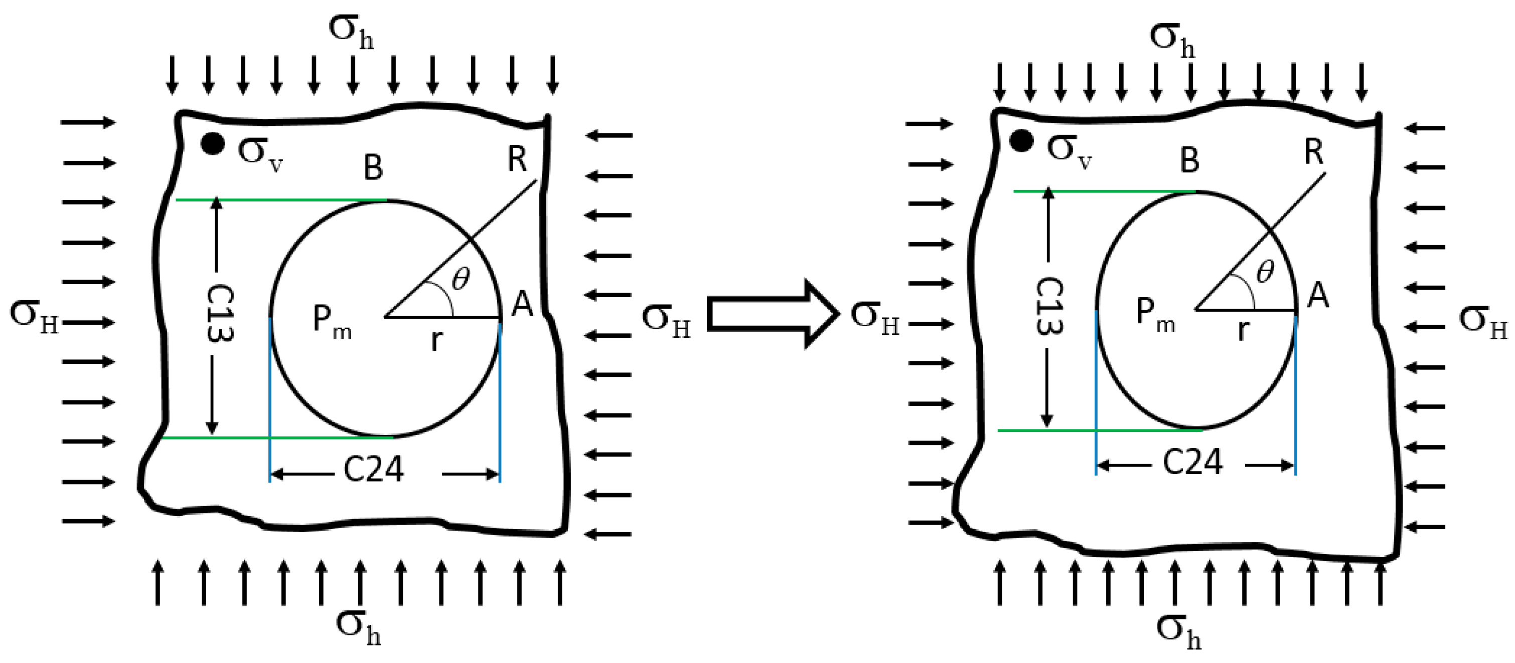
When a borehole is drilled, there will be several borehole shape scenarios (depending on the mud pressure, geomechanical properties, and the in-situ stresses), such as breakouts, drilling-induced fractures, elliptical boreholes, circular holes, or the combination of two or more of these events. If the borehole rock has not yielded under two deferent stresses that are orthogonal to the borehole cross section, an elliptical borehole will be formed, as shown in
Figure 1, with a vertical borehole considered as an example.
According to the elasticity theory, elastic solids subjected to loadings will deform, and these deformations can be quantified by knowing the displacements of material in the body [
21]. When a circular hole is drilled, the displacements around borehole can be written as:
where:
r is original borehole radius;
R is the distance from borehole center;
μrr is the displacement of the borehole at
R distance from the borehole center;
is Young’s modulus;
is Poisson’s ratio;
is vertical stress;
is maximum horizontal stress;
is minimum horizontal stress;
Pm is borehole mud pressure;
θ is the angle from maximum horizontal stress direction.
When
R =
r, the displacement at the wellbore wall can be calculated by:
On the borehole wall along the maximum horizontal stress direction, point
A in
Figure 1, the displacement can be determined by:
On the borehole wall along the minimum horizontal stress direction, point
B in
Figure 1, the displacement can be determined by:
The longer axis (
C13) and shorter axis (
C24) of the four-arm caliper measurements, which are corresponding to the deformation of the borehole wall at point B and point A respectively, can be determined by the Equations (5) and (6):
Therefore, the relationship among the caliper measurements (longer axis
C13, shorter axis
C24), geomechanical properties, and in-situ stress can be described as follows:
3. FR-GA-ANN Method
Theoretically, in a vertical well, if Young’s modulus, Poisson’s ratio, vertical stress, original borehole size, borehole pressure, and two horizontal stresses are known, Equations (7) and (8) can be applied to calculate the longer and shorter diameters of the elliptical borehole. In actual cases of a drilled borehole, the longer and shorter diameters can be measured by four-arm-caliper tools. Vertical stress can be calculated form overburden weight using density logs. Borehole pressure can be estimated form mud weight. Young’s modulus, Poisson’s ratio, and two horizontal stresses are usually unknowns. Although bit size is known in any drilling process, the borehole size is not supposed to be equal to it, due to the factors such as lithology, erosion, damage and whirling of the bit. Therefore, for a drilled hole at certain depth, with known vertical stress and mud weight, there will be five unknowns (Young’s modulus, Poisson’s ratio, two horizontal stresses, and borehole size) and two knowns (longer and shorter diameters measured form calipers logs) in Equations (7) and (8).
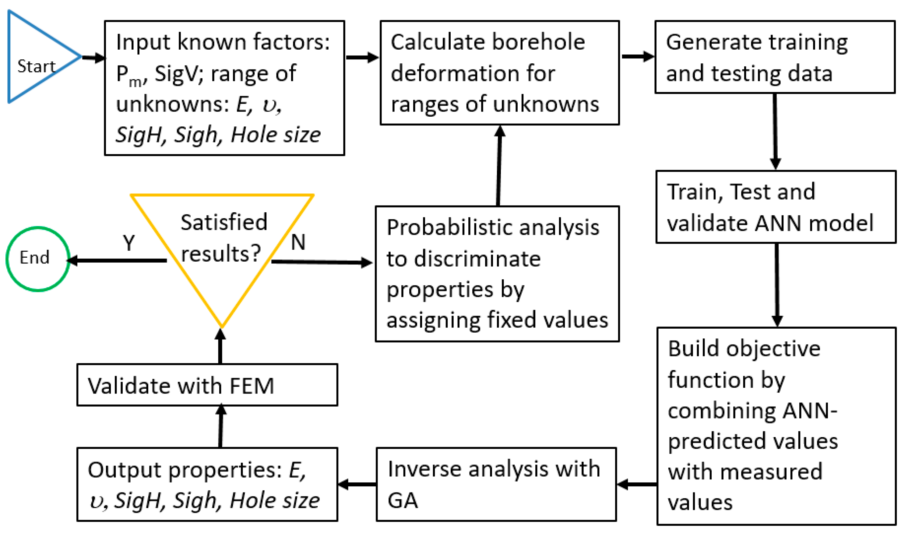
In order to solve the unknowns with the limited known parameters, we developed a method that combines artificial neural network (ANN), genetic algorithm (GA), and probabilistic analysis.
The ANN model was first developed by McCullock and Pitts [
22]. Since then, ANN models have evolved and have been considered a modeling tool in finding patterns based on the characterized relationship between the inputs and outputs. Once the relationship between inputs (e.g., geomechanical parameters in this paper) and outputs (e.g., borehole deformations in this paper) from training samples has been established, the ANN model forwards the relationships to GA for further estimation of in-situ stress and geomechanical properties based on the desired wellbore displacements.
GA was introduced by Holland [
23] as an abstraction of biological evolution. The method is used to search and optimize parameters based on the model of natural selection and natural genetics. Initially, the GA starts with values to the solution of a problem, known as the population. Inside the population, there are several potential solutions called chromosomes that can change to converge on an ideal solution. As these chromosomes evolve over time through several successful iterations, known as generations, stronger chromosomes will be generated, which are evaluated by the objective function (fitness). The chromosomes that have a stronger fitness are more likely to be selected in the evolution process [
24,
25]. Once certain chromosomes have been selected, they become parents and are combined together with other parents to produce new chromosomes for the next successive generation through the genetic process.
However, because of the large number of unknown parameters, more than the number of equations, there could be multiple combinations of in-situ stress, geomechanical parameters and borehole size that all lead to the same borehole deformation. To solve this dilemma, we adopted the probabilistic analysis for a number of realizations of the ANN-GA model. After each probabilistic analysis, the obviously higher frequency value for certain parameters will be identified. Then the specific values for these parameters will be chosen to be locked, and thus the total number of unknown parameters will be reduced for the next-run of ANN-GA model. The process is repeated until satisfied results are achieved with sufficient clarity. The final results will be further validated by finite element method to verify the relationship revealed by the ANN-GA model. We name this repeated probability analysis process as probabilistic recapitulation (PR). The work flow for the PR-ANN-GA method is shown in
Figure 2.
4. Case Study
In this section, the proposed PR-GA-ANN method is demonstrated by a field study in West Virginia, southern Appalachian Basin, USA. Drilling data and borehole geometry information of MIP 3H vertical drilling borehole were used for the determination of geomechanical properties and horizontal in-situ stresses.
At depth of 7538.5 feet (true vertical depth at 7536 feet) in Lower Marcellus formation of the MIP 3H well, drilling bit size is 8.75 inches, bore hole mud pressure while drilling is estimated to be 35 MPa, the vertical stress calculated from density log is 54 MPa, the measured longer borehole diameter
C13 is 8.91 inches, the measured shorter borehole diameter
C24 is 8.88 inches. The data is listed in
Table 1.
The input training and testing data for ANN are calculated based on the parameters listed in
Table 2. Totally 1024 combinations were generated. Thus 1024 sets of longer and shorter diameters,
C13 and
C24, were calculated through analytical calculation using Equations (7) and (8).
Once the ANN is trained, the inverse analysis modeling is used to characterize the relationship between input and output. Then fitness (objective function), the borehole longer and shorter diameters in this case, is established and GA is used as an optimization tool to search chromosomes (solutions) from a wide range of inputs that meet the established objective function. The chromosomes that have a stronger fitness are more likely to be selected as the results. Each modeling cycle runs 100 realizations for probabilistic analysis. The first 100 GA-ANN model realizations for five unknown input parameters are shown in
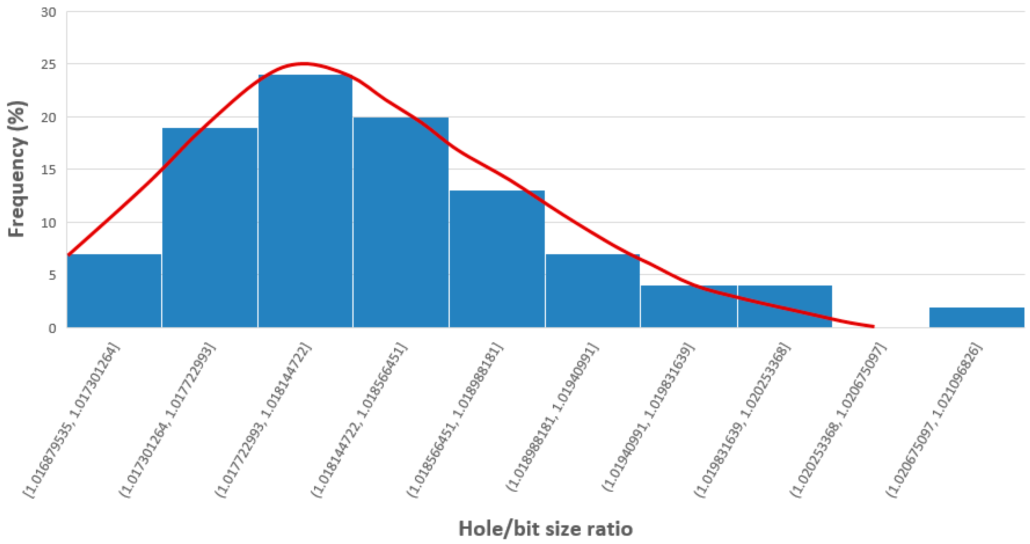
Figure 3. It can be seen that except the borehole size to bit size ratio, the rest four parameters, the Young’s modulus, Poisson’s ratio, maximum horizontal stresses, minimum horizontal stresses are evenly scattered without any obvious high frequency values. In the histogram of the borehole size to bit size ratio (
Figure 4), an obvious high frequency indicates a value about 1.018. The corresponding borehole size is 8.9075 inches.
Therefore, a hole size of 8.9075 inches was then applied as a known factor for the re-calculation of the training data with the ranges of Young’s modulus, Poisson’s ratio, maximum horizontal stresses and minimum horizontal stresses. The results of another 100 realizations of GA-ANN model with four unknown parameters is shown in
Figure 5. When compared with the five parameters results in
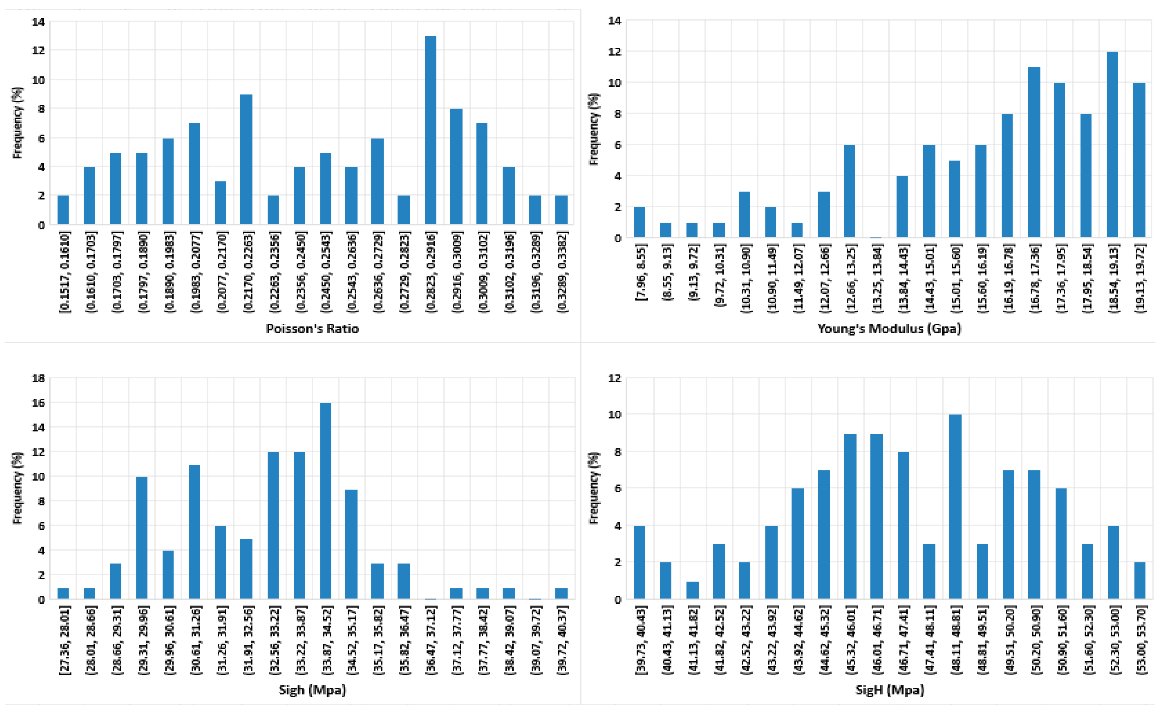
Figure 3, the value range of each parameters become a bit narrower; however, the values are still quite scattered without showing any constrained value. The histogram of these four parameters are shown in
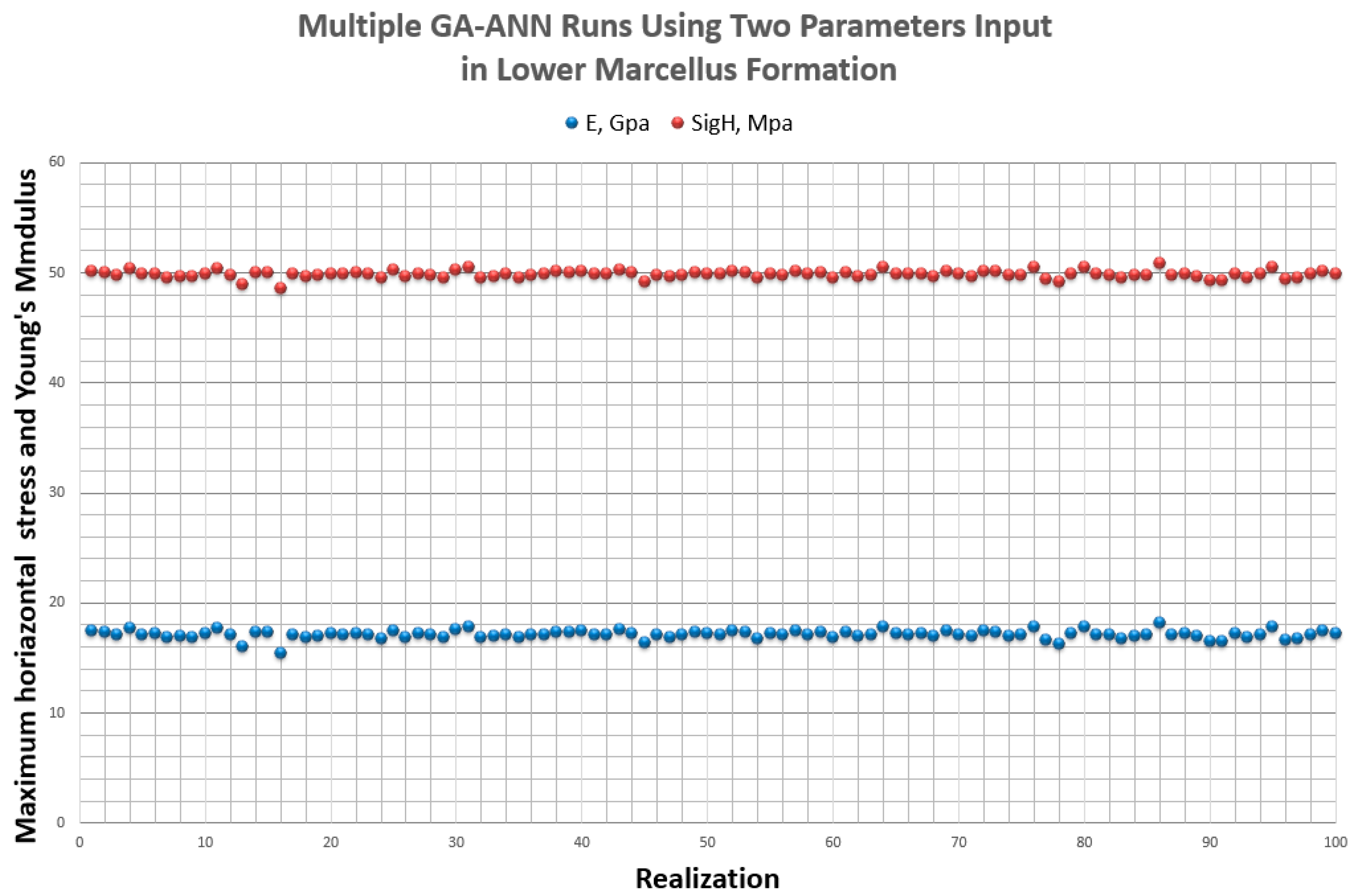
Figure 6. We chose the highest frequency value in the Poisson’s ratio at 0.285 and the highest frequency value of minimum horizontal stress at 34.2 MPa. Thereafter, the input unknown parameters can be reduced to three: Young’s modulus, maximum horizontal stresses. The results of 100 new GA-ANN modeling realizations for the reduced two unknown parameters are shown in
Figure 7.
It can obviously be seen from
Figure 7 that the calculated results of Young’s modulus and maximum horizontal stresses are quite consistent in multiple realizations. The average value for the Yong’s modulus is 17.1 GPa; the average value for the maximum horizontal stress is 49.8 MPa.
Therefore, in the case study of MIP 3H well, which was drilled in the lower Marcellus formation with 8.75 inches bit in the Appalachian Basin, if borehole mud pressure is 35 MPa, vertical stress is 54 MPa, the estimated borehole size should be 8.9075 inches. It was determined by PR-GA-ANN method that the maximum horizontal in-situ stress is 49 MPa, the minimum horizontal in-situ stress is 34.2 MPa, the Yong’s modulus is 17.1 GPa, and the Poisson’s ratio is 0.285.
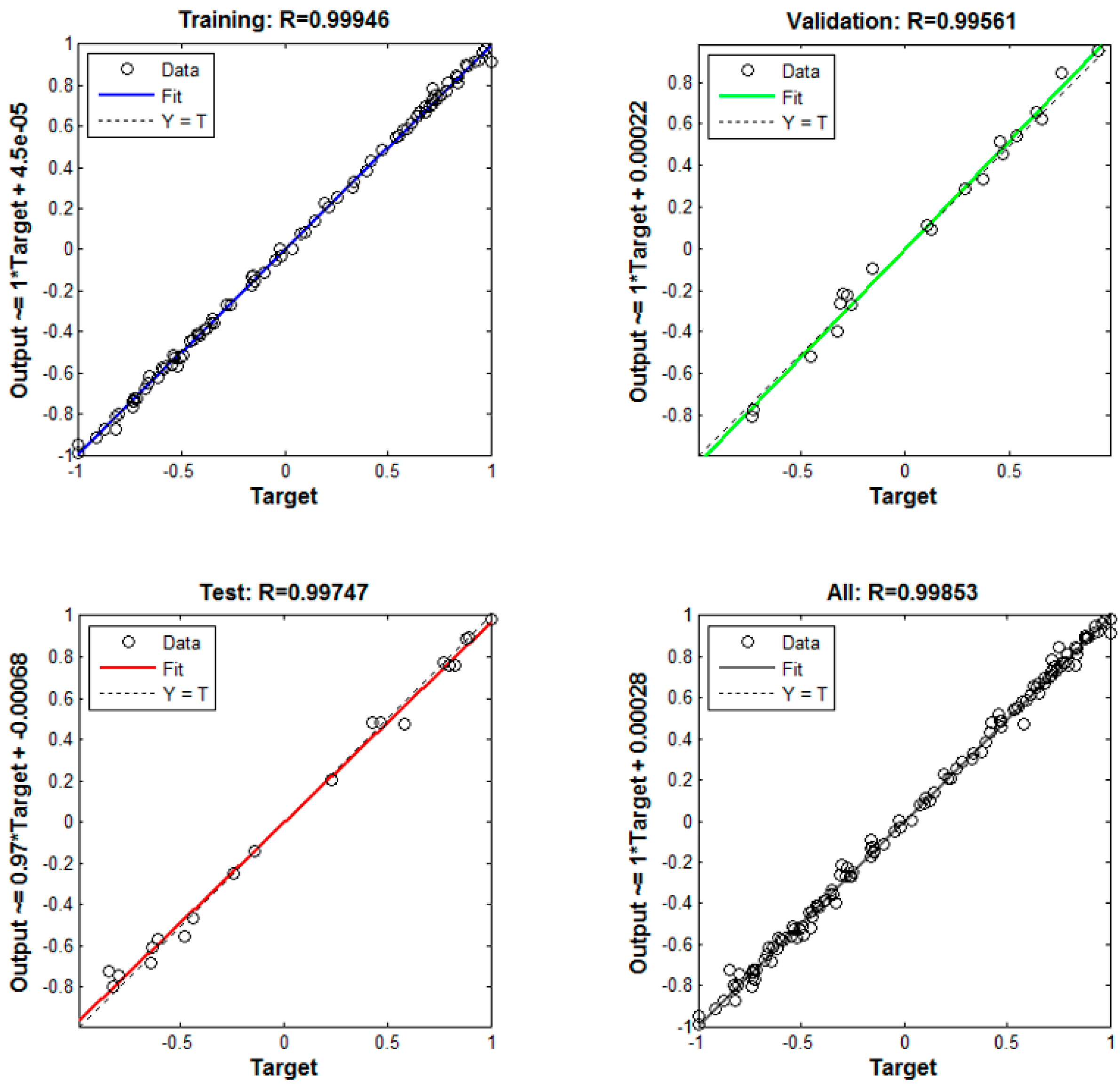
In order to verify each ANN model, the mean-square error (MSE) is used to evaluate the convergence of ANN.
Figure 8 shows the MSE variations for training, validation, and testing with iterations. The best validation performance is 2.59 × 10
−3.
Figure 9 shows the linear regression between the modeled output and the corresponding target. The regression values are shown on the top of pictures of training, testing, validation, and all samples respectively. All of the regression values are greater than 0.99, which meant very good performance.
5. Discussion
5.1. Comparison with Field Data
Table 3 shows the comparison of the PR-GA-ANN based inverse analysis results of geomechanical properties and horizontal in-situ stresses with the field observation or reports of the area for the well MIP 3H. The basin wide stress study indicated
σh/
σν value of up to 0.7 in the corresponding depth at this well location [
26]. With the vertical stress of 54 MPa from
Table 1, the upper bound minimum horizontal stress will be 37.8 MPa. The estimate by PR-GA-ANN in terms of minimum horizontal in-situ stress is consistent with this study.
Another source for verification of the minimum horizontal in-situ stress by PR-GA-ANN method is from hydraulic fracture treatment records. The first stage of the multi-stage hydraulic fracture treatment in this formation of the 3H well reported a pressure of 34.8 MPa that is 15 min after the instantly-shut-in-pressure (ISIP). The pressure is considered close to the fracture closure pressure, which is representative of the smallest principle in-situ stress, i.e., the minimum horizontal stress in this case. In this study, the estimated minimum horizontal stress of 34.2 MPa is in reasonable agreement with the field observations.
Evans also stated in the Appalachian Stress Study Report that the magnitude of
σH varies from high in the northern part of the basin to low values in the south; the stress state in the Devonian shale, of which Middlesex formation is a part, is either strike slip or normal fault regime due to the pinch-out of the underlying salt [
26]. The location of the studied well is around the pinch-out area [
27]. Therefore, unit value of
σH/
σν stress ratio should be an upper limit. That means the maximum horizontal stress should be smaller than 54 MPa, the vertical stress. This also validates the maximum horizontal in-situ stress estimated by the proposed PR-GA-ANN method.
5.2. Validation by Finite Element Method
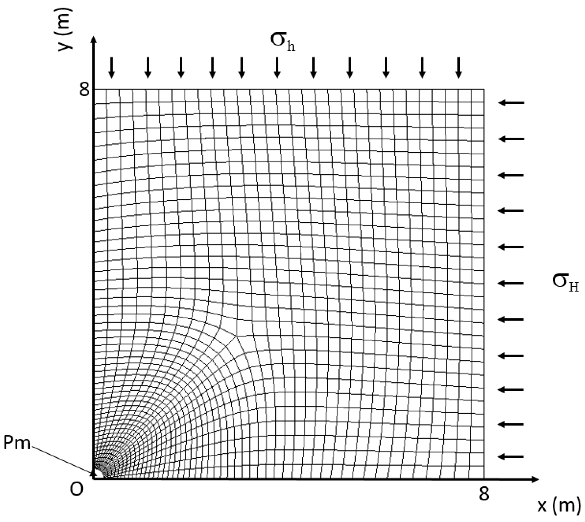
For a vertical borehole discussed in this paper, the deformation can also be forward calculated by finite element modeling [
28] if the rock mechanical properties and in-situ stresses values are available. In order to further validate the calculation, we used the calculated geomechanical properties and the horizontal in-situ stresses to forwardly calculate the borehole deformation using finite element method.
Figure 10 shows the mesh of the finite element model. The radius of the borehole used the half of the calculated original boreholes diameter, which is 4.46 inches. Parameters used for the finite element model, which are determined from the proposed PR-GA-ANN method, are listed in
Table 4.
Using the estimated 8.9075 inches as the original borehole diameter, the calculated shorter borehole diameter (
C24) is 8.880069 inches for the shorter axis of the elliptical borehole; while the calculated longer diameter (
C13) is 8.910139 inches. The ratio of the calculated shorter diameter and longer diameter is 0.996625. The finite element modeling results are listed in the
Table 5. When compared with the measured shorter and longer diameters reported from the four-arm caliper data, which are 0.88 inches and 8.91 inches respectively, the deference is minor and the errors are very small (around 10
−4 to 10
−5). The relationship that the PR-GA-ANN method revealed is in consistent with the calculations from the finite element method.
6. Conclusions
It is possible to estimate geomechanical properties and horizontal in-situ stresses from borehole deformation data. Uncertainties of results can be reduced by combining probabilistic analysis with GA-ANN method. Since there is no direct stress measurement and core mechanical test data for this well to calibrate the calculated results, future filed measurement or lab test work might be needed to further justify the methodology.
The correct estimate of borehole size is an important factor influencing the magnitude of borehole displacement and must be addressed different from bit size. This paper treats the original borehole size as an unknown input and estimate its value by inverse calculation from deformation data. However, the relationship between the bit size and the borehole size is still unknown. Future lab and/or field tests will be required to further validated the relationship.


