1. Introduction
Bluetooth is currently one of the most promising available ad hoc wireless connectivity technologies, and the introduction of its advantageous features is considered to be one of the main enablers of the Internet of Things (IoT) [
1]. Bluetooth Low Energy (BLE) technology [
2] can be embedded in existing mobile and portable devices, offering the advantages of a short-range radio, low power, and low-cost wireless connectivity. At present, globally there is wide use of smart devices such as smartphones, tablets, and laptops connected to multi-hop networks through BLE devices [
3]. Many BLE data applications are emerging in daily life, such as in health networks [
4], smart grid [
5], wireless sensor networks [
6,
7], etc.
With integrating the latest innovative communications, smart grid applications become increasingly popular, as they aim to meet the energy efficiency requirements [
8]. To improve the reliability and efficiency of power utilization, a smart grid is a combination of two-way data communications, distributed computing, and smart sensors. In addition, one application field is the home area network (HAN) [
9], where a communication path is created among smart meters, home appliances, and plug-in electronic devices. Among wireless protocols in recent years, new technologies are emerging aiming at an energy-efficient communication. A novel research activity has focused on BLE because it is an appealing solution in becoming a key technology for smart homes in low-power, low-cost, and small devices [
5,
10,
11]. However, these applications pose some important research challenges, such as how to connect BLE devices to share information among users, and how to form the desired network configurations for various types of applications.
Recently, the specifications of BLE 5 have been presented to offer significant enhancements that differ in range, speed, and energy consumption compared to the earlier versions of the protocol. Another main feature of BLE is that nodes can play dual roles as relays, and such relay nodes enable inter-piconet communication. The relay node design increases the possibility of implementing a scatternet formation algorithm and multi-hop routing for BLE devices. To-date, the development of multi-hop routing networks has faced some inherent technical challenges, including research design issues related to the formation algorithms [
12] and the routing protocols [
13,
14]. The problem involves how to construct individual piconets and connect them together into a scatternet. In addition, the routing protocols must deal with the problem of delivering messages efficiently in such scatternets.
Many scatternet formation algorithms have been developed to construct a multi-hop ad hoc network, and they can be classified into two categories. One category—the single-hop scenario [
15,
16]—deals with situations in which all nodes are within radio range. The other category—the multi-hop scenario [
17,
18]—handles situations in which not all nodes are necessarily within radio range. Most of the current scatternets in the multi-hop scenario are generated in a distributed manner [
19,
20,
21,
22]. In addition, a number of different topology models [
23] can be generated according to the desired purpose of the scatternet. Most of these scatternet models have been studied and can be generally categorized as tree-based, mesh-based, ring, or star topologies.
With a non-uniform distribution application, such as a conference hall or an intensive care unit in a hospital, Bluetooth hybrid ring-tree (BlueHRT) [
15] forms a ring topology in one dense area, which is connected with multiple tree subnets around the other sparsely covered areas. However, this protocol partitions networks by collecting complete topology information in a coordinator, and involves considerable formation overheads. In addition, using a ring subnet as the core network design is not reliable enough because it is vulnerable to significant failure if a node in the ring subnet fails.
In [
24], a dual-ring tree (DRT) protocol generates a dual-ring subnet in one dense area, which is connected to multiple tree subnets around the other sparsely covered areas. To consider the emerging probability of the multi-hop situation in the dense area, a distributed formation algorithm is presented to cope with the multi-hop instances, while a localized formation algorithm is proposed to cope with the pure single-hop instance. As a result, the DRT topology outperforms conventional BlueHRT in terms of network reliability and routing efficiency for Bluetooth networks.
The routing protocol design is another notable leading research issue for Bluetooth multi-hop scatternets [
25]. Thus far, many well-known routing protocols have been presented, including proactive [
15,
18], reactive [
26], and hybrid methods [
27] for Bluetooth networks. To achieve the route discovery with the least overhead, a self-routing protocol is presented for both tree [
28] and layer-ring topologies of the single-hop scenarios [
29]. Currently, the multi-hop self-routing protocol remains as a research challenge.
To extend the DRT architecture into a generalized n-ring network solution, a multi-ring tree with a multi-hop self-routing protocol is proposed. In order to determine the optimal configuration of one dense area and many sparse areas, an optimal multi-ring tree formation algorithm is presented herein. During the leader election phase (LEP), a leader root is elected and then connects to its neighboring nodes as a root in order to build the multi-ring subnet, thus improving the connectivity of the core network in the dense area. Each root in the multi-ring subnet then starts to build its corresponding tree-shaped subnet around other sparse areas. Finally, a multi-ring tree topology is constructed.
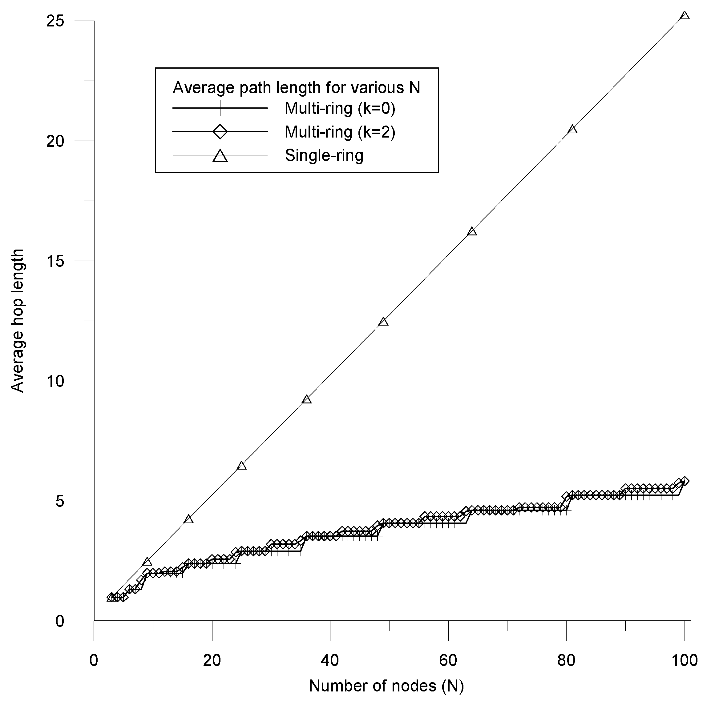
The multi-ring design aims to determine the optimal configuration for various sizes of network topology. To achieve this goal, a min-path algorithm is introduced to determine the optimal number of rings R and the best number of nodes in each ring P for various numbers of nodes N. With a constraint criterion between R and P, the resulting combination of R and P achieves the minimum hop length locally and constructs a more symmetrical multi-ring subnet. To efficiently deliver packets for both multi-ring and tree subnets, a self-routing protocol is an energy-efficient solution to achieve the least route discovery overhead for a multi-hop scenario.
The remainder of this paper is arranged as follows.
Section 2 proposes the detailed operation of the multi-ring tree formation algorithm.
Section 3 presents a self-routing protocol with a self-healing scheme to efficiently maintain the topology and deliver packets over the multi-ring tree network.
Section 4 demonstrates the optimal configuration and routing performances via computer simulations. Finally, conclusions are drawn in
Section 5.
2. Formation Algorithm
2.1. Motivation of Multi-Ring Design
It is assumed that a non-uniform environment is concentrated in a certain area with higher density, while the other extended areas are sparse areas. The high-density area belongs to the one-hop scenario and is designed as a multi-ring subnet. The other extended sparse areas belong to the multi-hop scene, which can be designed as a tree subnet. With the hybrid network design for the non-uniform scenario, the multi-ring tree benefits from both ring and tree network advantages.
To generate a multi-ring subnet, a coordinator discovers and configures neighbor information N into the desired multi-ring subnet. The resulting multi-ring subnet can be the backbone network for the highly dense area. On the other hand, the discovered number of nodes N can be a random variable for various scenarios. Therefore, how to plan N into the optimal R-layer multi-ring architecture is an interesting research issue.
Two main situations are considered in the design method: the first is how to form the desired multi-ring subnet, and the second is how to achieve the optimal configuration with the minimum multi-ring path length. Because N is a variable number, it can be divided into two general cases: prime number and composite number cases. When N is a prime number, N decreases by 1 until it is decomposable, since the prime case cannot form a multi-ring. When N is decomposable, , where R is defined as the number of rings and P is defined as the number of nodes in each ring. In addition, to minimize the average path length of the multi-ring network, designing the symmetry multi-ring configuration to make the value of R and P as close as possible is intuitive.
When N is decomposed into R and P, it is found that some N have many combinations of R and P. Therefore, all possibilities of combinations need to be calculated, and the corresponding average path lengths must be compared to determine the optimal configuration of N. To make the multi-ring close to a symmetrical configuration, it is better to make R and P values closer in the multi-ring design. As a result, a constraint is proposed to limit the difference between the R and P to make the resulting network more symmetrical. At the same time, the constraint design also reduces the computational complexity of all possible combinations to more quickly determine the desired configuration.
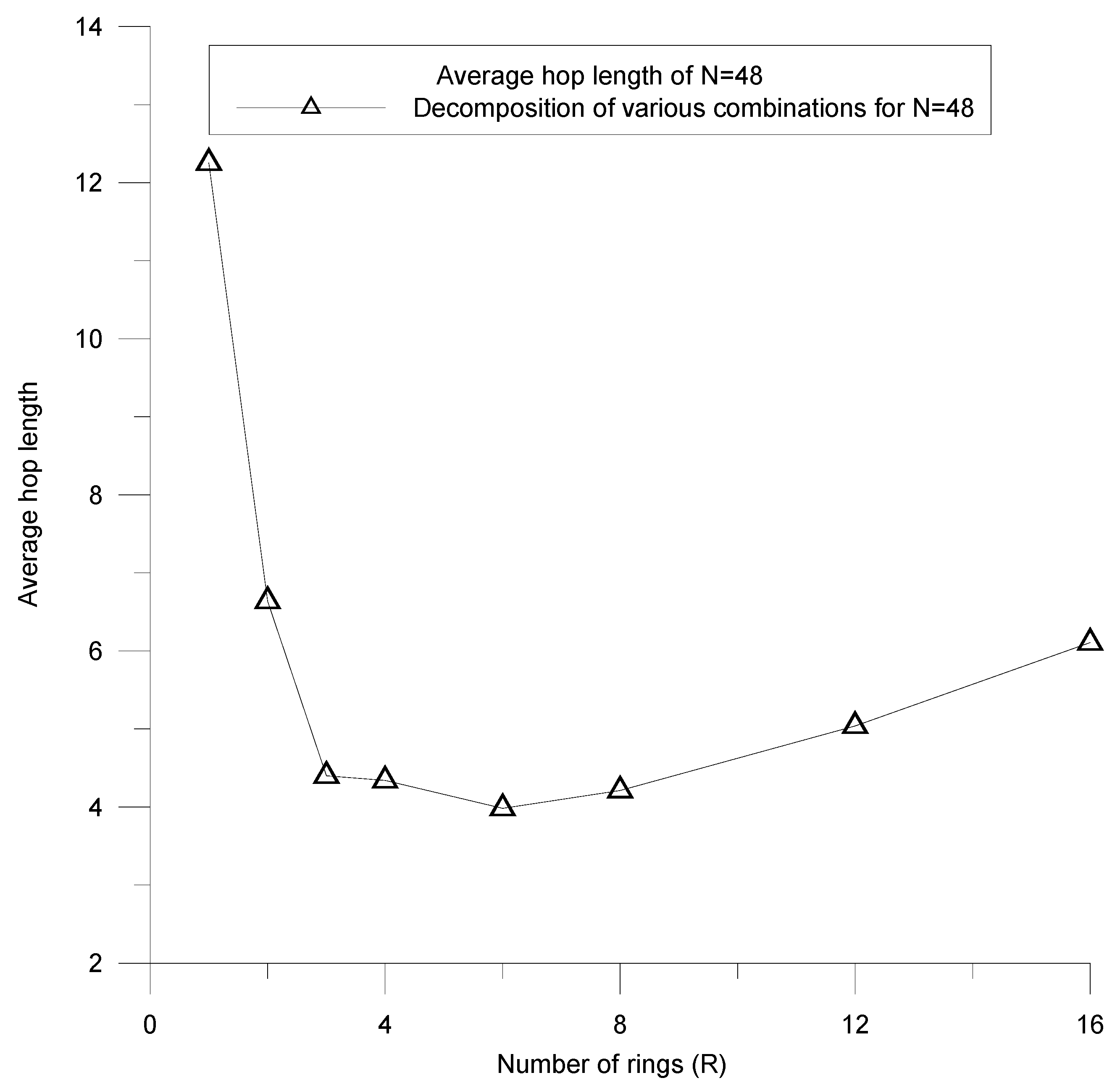
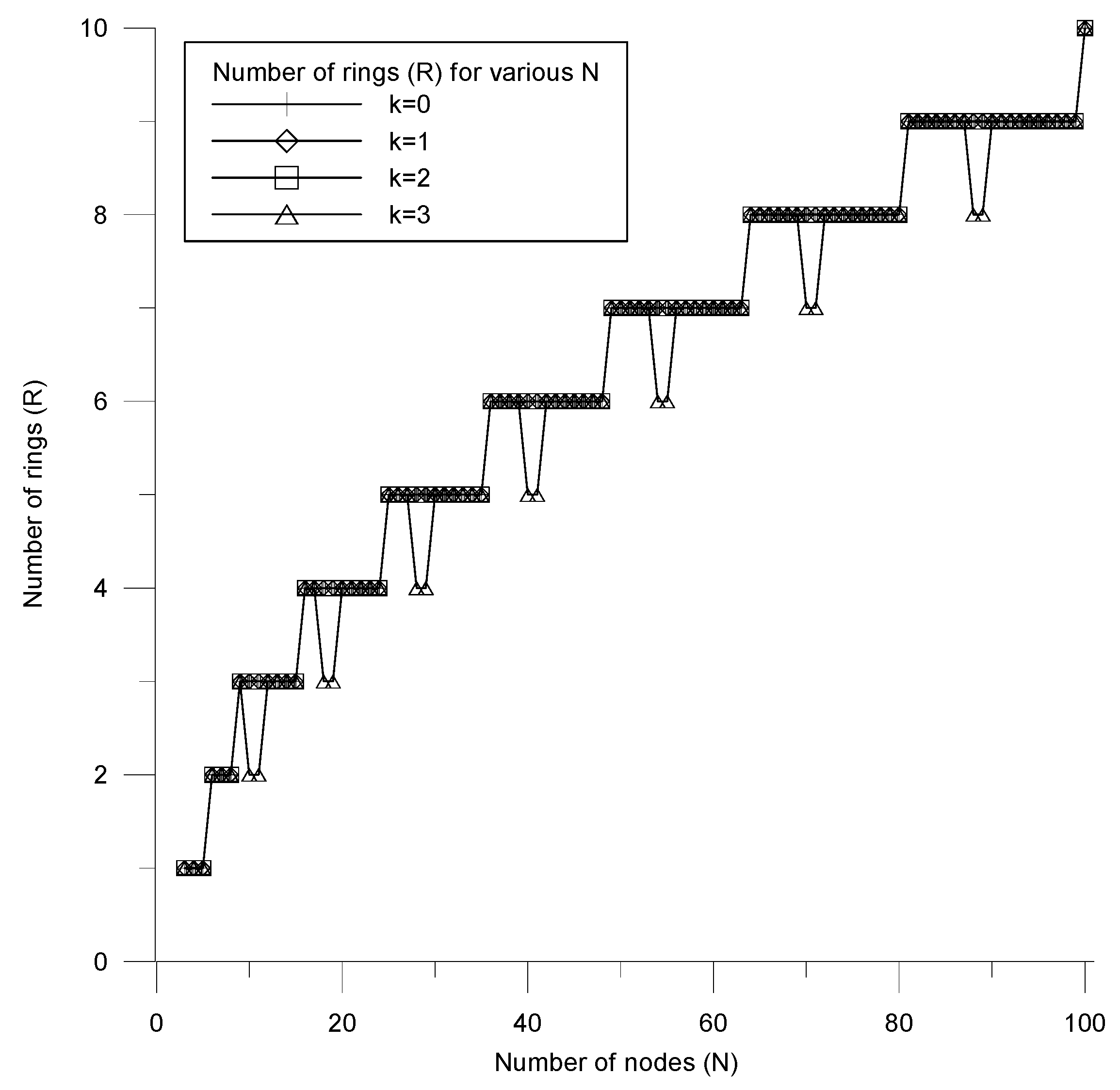
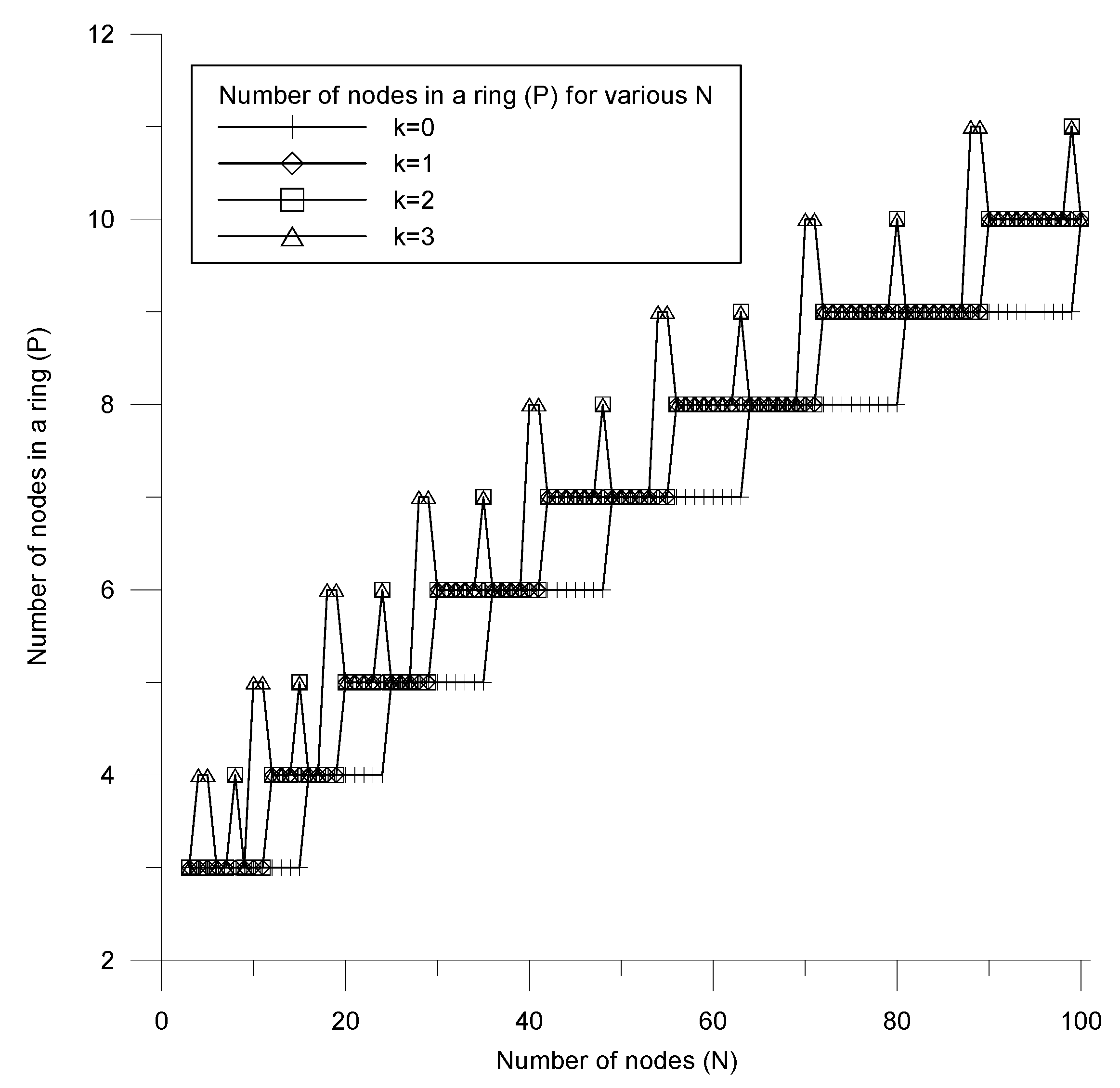
In the example of
N = 48, there are eight decomposable multi-ring combinations except the cases (24, 2) and (48, 1) since at least three nodes are required to form a ring subnet. After calculating the various cases, the path length result of each combination is shown in
Figure 1, which shows a minimum point when
R = 6 with
P = 8; this case achieves the minimum path length compared to all the other combinations. At the same time, the number of computations can be effectively reduced from eight to two if the constraint of
R-
P is set to four, thus improving the computation time required to determine the best configuration.
Based on the above design points, we aim to develop a min-path algorithm to effectively determine the optimal multi-ring configuration. With an arbitrary given N and constraint in the min-path algorithm, the system model can be formulated to quickly compute and search for the minimum point of the path length performance, and the most suitable R and P can be effectively determined.
2.2. Multi-Ring Tree Formation Algorithm
2.2.1. Min-Path Algorithm
In order to improve the topology’s reliability, other than the conventional single-ring network, this work proposes a multi-ring tree scatternet formation algorithm. The multi-ring subnet as a core network design effectively improves network reliability. To effectively form the desired topology, the algorithm discovers the topology only in the dense area instead of the global area as the conventional single-ring network does, in order to reduce the computation and communication complexity. In the dense area, a min-path algorithm is also presented to determine the optimal configuration of the multi-ring subnet.
During the node discovery phase (NDP) [
30], each node alternatively operates as a scanner or an advertiser by a scan probability
p. In the multi-ring tree, a node plays a scanner if its probability
p is greater than 0.5, or as an advertiser otherwise. In a time interval
T, each scanner increases its neighbor count by one when receiving an advertising message from a new neighbor. After the completion of NDP, a leader election phase (LEP) is started afterward. When two nodes meet, the node with the higher neighbor count value wins the role as a master and the other one plays a slave. During the connection, each slave sends its collected neighbor information to the master and stops to advertise message. When two nodes have the same neighbor count value, the node with the lower ID becomes the master. In this way, the masters continue to scan neighbor information and compare their neighbor count values by exchanging advertising messages. At the completion of LEP, the last master is elected as a leader root with the maximum neighbor count value in the dense area.
At the end of LEP, a leader root discovers the local topology with
N roots’ information in the dense area. The min-path algorithm is introduced here to determine the local optimal topology of the multi-ring subnet. In the algorithm, the input parameter is
N, and the output parameters are the number of rings
R and the number of nodes in each ring
P, where
N can be factorized into the
R-ring and
P-node in each ring. The minimum value of
R and
P is 1, and the maximum value of
R and
P is
N. The decision criterion is compared by the average hop length
H, where
is a function of
R and
P for a given combination
i, where
m is the maximum value of
i. When many decomposable combinations
i exist for any given
N, the minimum point needs to be discovered by comparing the average hop length
. To minimize the computation complexity of
H(
R,
P), the constraint criterion
is also introduced, where
k is a constant; the smaller
k reduces the computation complexity of the min-path algorithm. The min-path and the constraint criteria can be expressed as Equations (1) and (2), respectively.
The smaller k for each N intuitively brings the R closer to the P. The resulting topology is more approximate to the symmetry deployment. However, when N is not decomposable, N decreases by 1 until the value can be factorized and the constraint is satisfied. On the other hand, when N is decomposed into R and P, if does not satisfy the constraint, then N decreases by 1 until it can be decomposed into R and P. Finally, the optimal configuration with the least hop length can be decided, and the suitable combination of R and P can be found. In addition, the closer R and P can satisfy the constraint, the better is the formation of a more symmetrical multi-ring configuration.
When N = 34 and the constraint , N can be divided into (R = 1, P = 34) and (R = 2, P = 17); the resulting R and P sets do not meet the constraint. Next, N decreases by 1 into 33 with (R = 1, P = 33) and (R = 3, P = 11) sets, which do not satisfy the constraint. Here, N decreases by 1 again until the constraint is satisfied by two computed sets: (R = 4, P = 8) and (P = 8, R = 4). As a result, the optimal configuration can be determined by comparing the average hop length of (R = 4, P = 8) and (P = 8, R = 4); the resulting configuration is (R = 4, P = 8).
2.2.2. Multi-Ring Tree Formation Algorithm
After determining the local optimal configuration with suitable R and P, the leader root connects its one-hop neighboring nodes to form the multi-ring tree scatternet. The neighboring nodes can then be regarded as the first-tier new roots, and the leader root connects them together into the first-tier ring subnet. The number of roots in the first-tier ring is P. Once the first-tier ring subnet is formed, each root at the ring subnet connects to one neighboring node as the second-tier new root. The roots at the first-tier ring propagate their second-tier new roots’ information and instruct them to connect with each other to form the second-tier ring subnet. In this way, the third-tier roots are discovered and connected until the desired R-tier ring subnet is achieved. As a result, a multi-ring subnet is constructed, and the bridge node can be a master/slave or a slave node.
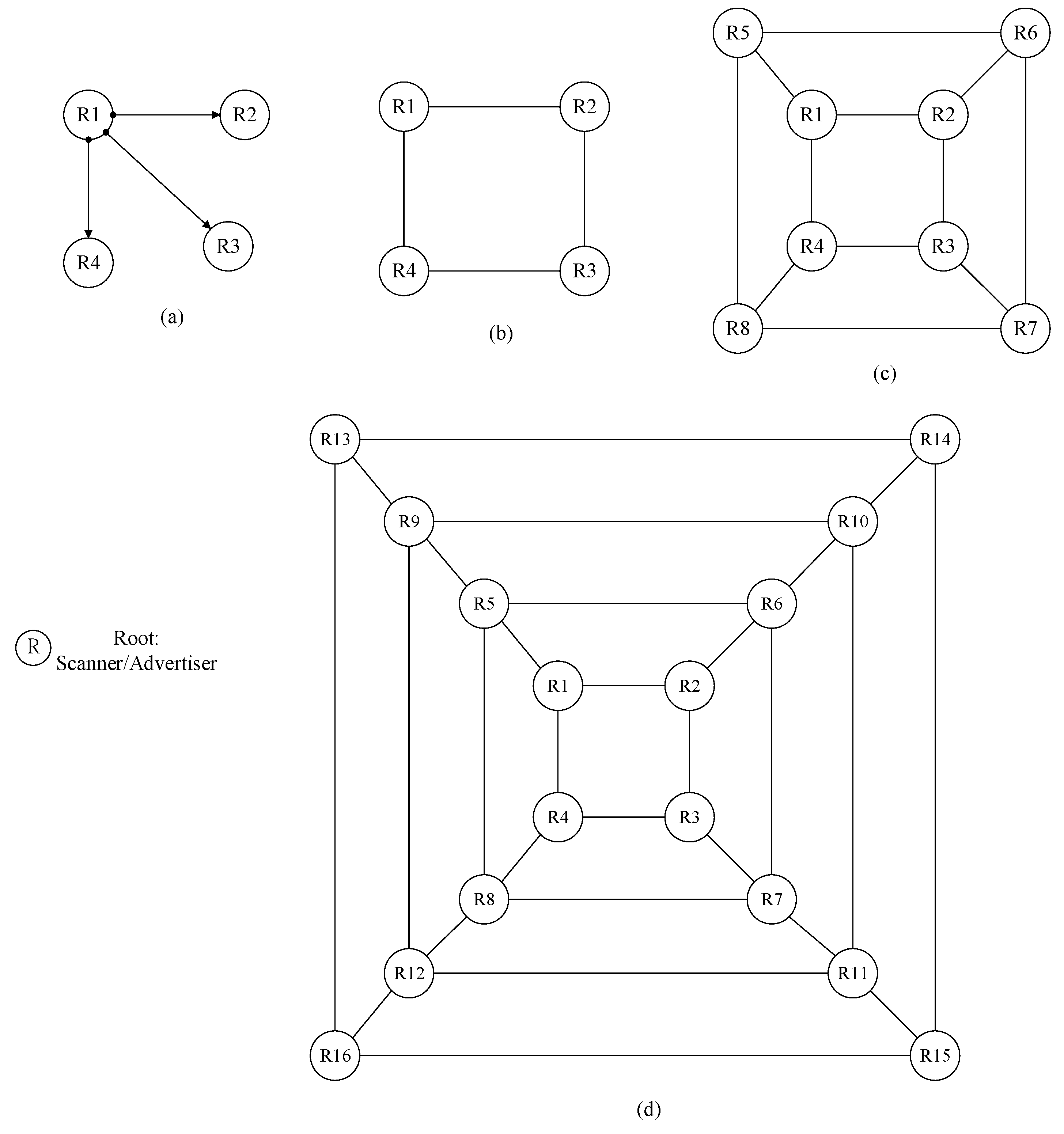
Using N = 17 and as an example in the dense scenario, a leader root R1 discovers 16 other neighboring nodes. The min-path algorithm is executed by the coordinator R1, and N is decreased by 1 into 16 since the initial N is a prime number. The leader root then computes all possible (R, P) sets, including (1, 16), (2, 8), (4, 4), and compares them with the constraint. As a result, the (4, 4) set satisfies the constraint and the optimal configuration is determined.
After determining the optimal configuration with
R = 4 and
P = 4, the leader root assigns the identification sequentially from R2 to R16 for all other roots and computes the connection information for each root. Here, R1 propagates the connection information for root candidates of the first-tier ring R2, R3, and R4, as shown in
Figure 2a. The first-tier ring is formed by connecting R1, R2, R3, and R4, as shown in
Figure 2b. Each root in the first-tier ring then connects with its downstream root and propagates the connection information for them to form the second-tier ring, as shown in
Figure 2c. In this way, the 4 by 4 multi-ring is generated until the outermost 4-ring is reached, as shown in
Figure 2d.
Figure 2 illustrates the formation process of the optimal multi-ring subnet in the dense scenario.
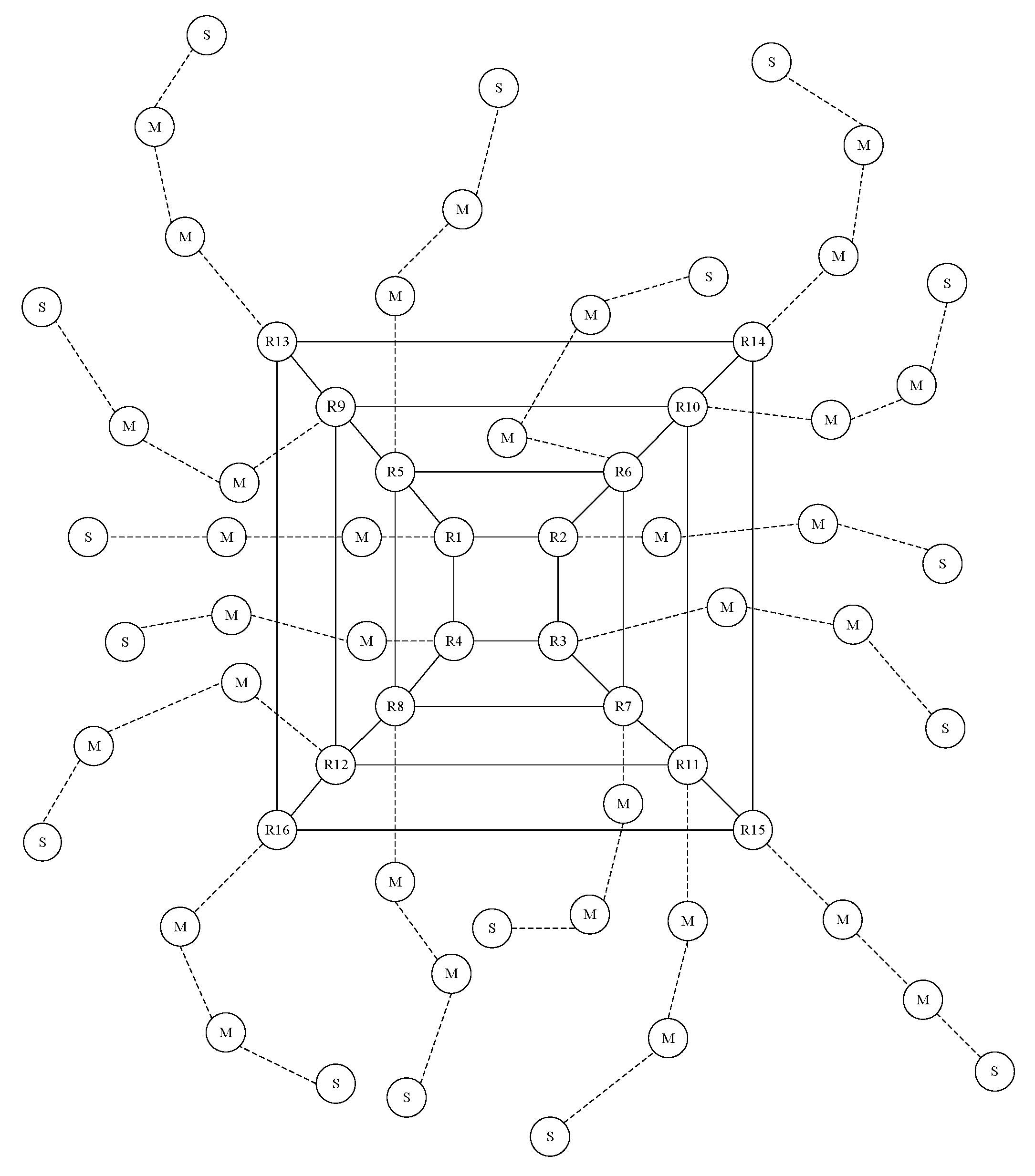
After the multi-ring subnet is generated, each new root in the multi-ring serves as a coordinator and begins to scan its neighboring advertising message and connects them to form their own piconets. The connected slaves then switch their roles to masters (called M/S nodes), and each M/S node repeats the same scan procedures as the root, while also connecting its advertisers to form its own piconet. This procedure is performed iteratively until the leaf nodes of the tree are reached. An illustrated example of the multi-ring tree scatternet with
N = 16,
R = 4, and
P = 4 is shown in
Figure 3. In addition, the pseudo code of the multi-ring tree scatternet formation algorithm is listed in Algorithm 1.
| Algorithm 1 The pseudo-code of the multi-ring tree formation algorithm. |
// The algorithm design is for a topology formation method to construct the optimized multi-ring subnet. Input parameter N: N is number of roots;
Constraint:;
Output parameter (R, P): R is number of rings; P is number of nodes in each ring. //
Init: A designated root discovers N neighboring roots including itself in a dense area.
if N is not decomposable
decrease N until the value of N is decomposable
else find all possible combination (R, P) of N
if , calculate the average path length for the corresponding sets and output the set (R, P) with the minimum path length according to Equation (1).
endif
endif
A. Multi-ring formation procedure:
Init: With the optimal configuration (R, P), the designated root assigns the identification sequentially from R(2) to R(N) for all other roots.
if the paged root reaches the R-tier ring,
the multi-ring subnet is formed
else a paged root receives connection information from its upstream root and it starts to connect with its neighboring root to form a ring and connects with its downstream root
endif
B. Tree formation procedure:
Init: The paged root forms the R-tier rings with P roots in each ring.
if the leaf node is reached
the multi-ring tree is formed
else the paged slaves then switch their roles to masters and connect their paged slaves to form its own piconet.
endif |
3. Routing Protocol
3.1. A Self-Routing Algorithm
In order to effectively deliver a packet in the multi-ring tree scatternet, this work also presents a self-routing protocol with a shortest path criterion. The self-routing algorithm for one single-hop with multi-hop scenarios can achieve the least overhead route discovery compared to the other traditional routing protocols.
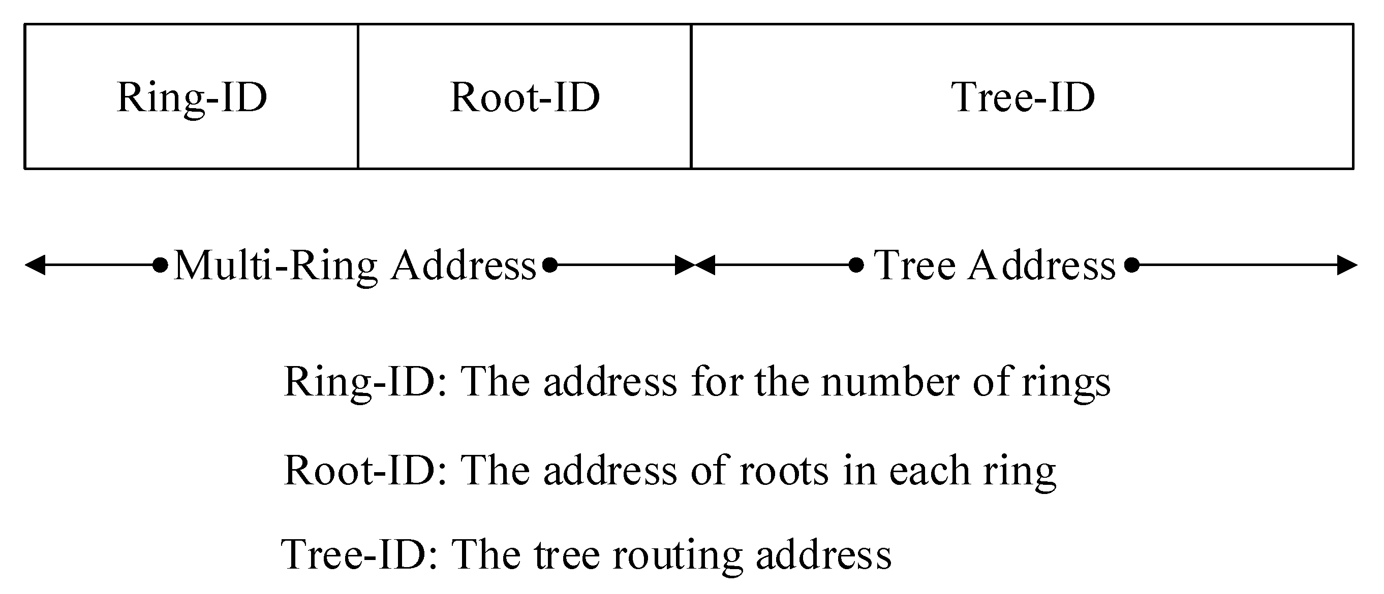
Figure 4 shows a packet address field of the multi-ring tree. The routing protocol designs three types of scatternet address field: the Ring-ID, Root-ID, and Tree-ID in the packet header to achieve the self-routing capability. The packet field of Ring-ID with
bits serves to specify the number of rings in the multi-ring subnet. The packet field of Root-ID with
bits addresses the number of roots in each ring. The Tree-ID defines all the downstream nodes in each root. In addition, the slave node is addressed by the Bluetooth AM_ADDR in a piconet. With these three types of address, each node can deliver packets to the desired destination node in a multi-ring tree network.
During the scatternet formation, a two-stage addressing method for the multi-ring tree is proposed. The first stage is to define the address for the multi-ring, and the second stage is to define the spanning tree address for the self-routing protocol. In the first stage, the Ring-ID is set to 1 for the roots in the first-tier ring, and the Root-ID is set to 1 for the leader root. In this way, the Ring-ID is set to 2 for the roots in the second-tier ring, the Ring-ID is set to 3 for the roots in the third-tier ring, and finally the outermost ring Ring-ID is set as R. At the same time, the Root-ID of roots in each ring is set by a constant counter r, where .
The second stage presents a tree-addressing criterion specifically to all nodes in each spanning tree for the multi-hop scenario. Each root with Tree-ID = 0 connects with its downstream nodes with Tree-ID = 1, and the Tree-ID sequentially increases by 1 until 7 for the most connected nodes in the first-tier tree. The master in the first-tier with Tree-ID = 1 then connects with its downstream layer nodes with Tree-ID from 8 to 14, and the master Tree-ID = 2 assigns its connected nodes with Tree-ID from 15 to 21. In this way, the master with Tree-ID = 8 connects with its downstream nodes and assigns the third-tier nodes Tree-ID from 57 to 63, so that each upstream master can forward the packet to the destination node according to the Tree-ID. In summary, the address range of Tree-ID in the each-tier tree is assigned with the tree-addressing criterion by its parent with pTree-ID from (7 × pTree-ID) + 1 to 7 × (pTree-ID + 1).
With the destination Tree-ID = 24 as an example, the root of the destination receives the packet and computes the ID = 24 by the tree-addressing criterion. The destination is located at the address range of its third connected master, and the packet will be forwarded to the parent master of the destination. The parent master in the first-tier then forwards the packet to the destination node, since ID = 24 is the directly connected node of this master.
To reduce the packet length of a larger ring subnet and efficiently deliver packets, a shortest path criterion is defined as Equation (3) to minimize the hop distance between root
i as
and root
j as
. When a root in the ring subnet receives a new packet either from the tree subnet or the ring subnet, the Root-ID of the destination root will be checked with its own Root-ID by Equation (3). If
j is greater than or equal to
i and Equation (3) is satisfied, then the packet will be forwarded in a clockwise direction in the ring subnet; otherwise, the packet is forwarded in a counterclockwise direction. If
j is less than
i and Equation (3) is satisfied, then the packet will be forwarded in a counterclockwise direction in the ring subnet; otherwise, the packet is forwarded in a clockwise direction.
The packet routing of the multi-ring tree network is generally classified into two cases: the intra-root and the inter-root routing. In the intra-root subnet routing case, a source node and a destination node are located at the same tree subnet under a root; the addresses of the Ring-ID and Root-ID in the packet header are the same. The destination of the root then computes the location of the destination according to the Tree-ID and forwards it to the destination via the resulting paths of the tree-addressing criterion.
In the inter-root subnet routing case, the packets are first forwarded from the tree subnet to the root of the source node. The source root then checks the Ring-ID and delivers packets to the ring layer of the destination root by the Ring-ID. After the packets are delivered to the ring layer of the destination, the packets are propagated to the root of the destination according to Equation (3). Finally, the destination root transmits the packets downstream to locate the destination node by the intra-root routing method when the destination is in its spanning tree subnet. As a result, the scatternet self-routing protocol of the multi-ring tree can be achieved by the proposed addressing method. In addition, the pseudo code of the multi-ring tree self-routing algorithm is listed in Algorithm 2.
3.2. A Self-Healing Scheme
A self-healing protocol can be achieved, since the multi-ring tree address scheme enables the maintenance of self-routing networks. This work considers four cases in the proposed self-healing protocol: a new node joining the network, a slave node failure, a master failure, and failure of one or two roots. When a node joins or fails in a piconet, each master adds a new AM_ADDR address for the new slave or deletes the slave connection from its piconet list, respectively. If a master/slave node leaves, the first slave node with the smallest AM_ADDR address becomes the new master; it connects all the other slaves with the same ring-tree address. In addition, the new master provides an update status for its affiliated root node.
When a root node in a ring subnet leaves, the slave node with the smallest AM_ADDR address in the piconet becomes a new root and sends out a root update message to its affiliated slaves and its directly connected neighboring roots. The topology maintenance for a single failed node can be applied for cases with two failed roots, since two failed roots are disconnected independently. For example, in
Figure 3, if root R10 fails, then the candidate slave with the capability to connect with current directly connected roots in the R10 piconet becomes a new root, and the new R10 sends a root update message to its directly connected roots R6, R9, R11, and R14. When R1 and R6 both fail, their slaves become the new roots independently and coordinate their corresponding slaves. As a result, the multi-ring subnet still can be maintained locally.
| Algorithm 2 The pseudo-code of the scatternet self-routing protocol |
Init: When an immediate node m receives a packet for destination node n.
If m(Ring-ID, Root-ID) = n(Ring-ID, Root-ID)
then call intra_root(n)
else call inter_root(n)
endif
A. intra_root(n):
Init: The immediate node m receives a packet and checks the Tree-ID of the destination.
If m(Tree-ID) = n(Tree-ID)
then the destination node is reached
else the m computes the location of the destination by a tree-addressing criterion and forwards the packet to its downstream piconet until m(Tree-ID) = n(Tree-ID)
endif
B. inter_root(n):
Init: The immediate node m receives a packet and checks Ring-ID of the destination.
root_search(n):
If m(Ring-ID) = n(Ring-ID)
then the node m computes the destination root by equation (3) and forwards packets until the m(Root-ID) = n(Root-ID)
if m(Tree-ID) = n(Tree-ID)
the destination node is reached
else call intra_root(n)
endif
endif
if m(Ring-ID) > n(Ring-ID)
then forwards the packet to the inner ring until m(Ring-ID) = n(Ring-ID)
and call root_search(n)
elseif m(Ring-ID) < n(Ring-ID)
then forwards the packet to the outer ring until m(Ring-ID) = n(Ring-ID)
and call root_search(n)
endif |


