A Novel Method for Idle-Stop-Start Control of Micro Hybrid Construction Equipment—Part B: A Real-Time Comparative Study


 ,
,
Abstract
:1. Introduction
2. Powertrain and PISSC Review
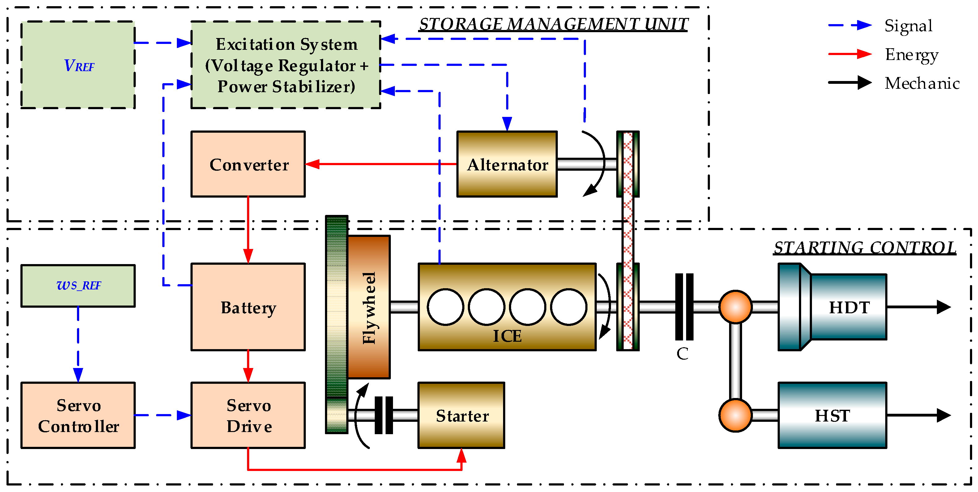
2.1. Powertrain Architecture
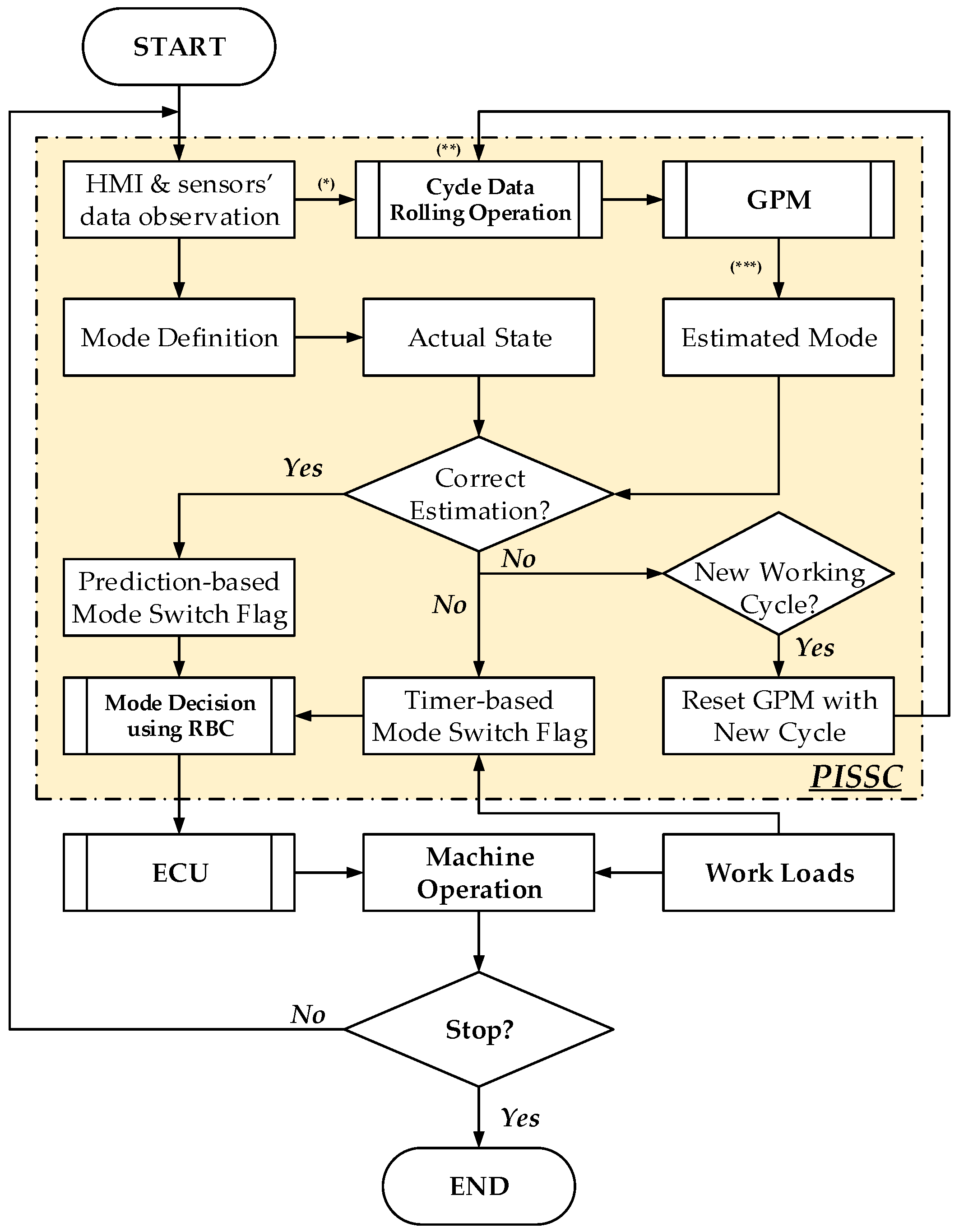
2.2. PISSC-Based Engine Control Design Review
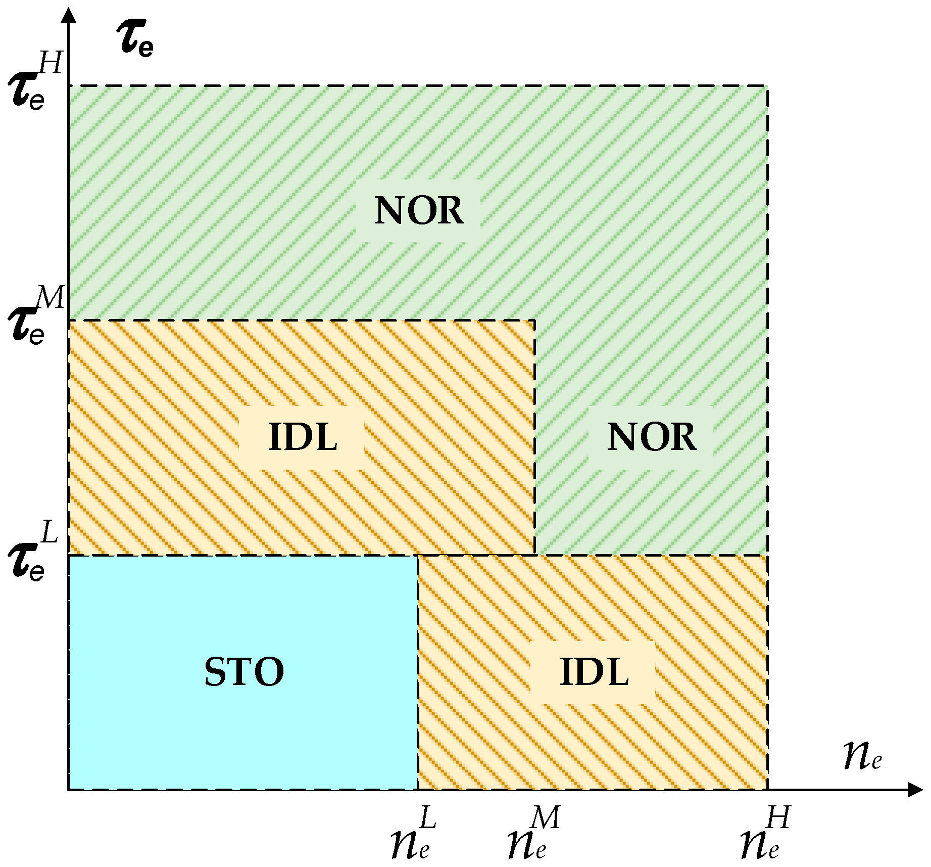
- and are the engine torque and speed, respectively. Their high, medium and low levels are in turn defined as: and .
- Normal mode (NOR): the machine requests the engine to run with full power capability. The starter does not operate during this mode.
- Idle mode (IDL): the machine does not request the full engine power. The cylinder deactivation control technology can be employed to reduce the engine power. The starter does not operated during this mode.
- Stop mode (STO): there is no command given from the human machine interface (HMI) module and the ICE torque and speed are below the low torque and speed levels, respectively (the ICE torque is mainly come from the system inertia). During this mode, the engine can be shut down to save the fuel and the starter is also turned off.
- Start mode (STA): the engine is cranked from zero speed to its normal idle speed (around 900 rpm). The starter is firstly turned on to crank the engine to a low idle speed (around 250 rpm). At this low idle speed, the starter is turned off while the injector starts to inject fuel to continue to crank the engine to the desired idle speed.
- A machine working cycle is a sequence of machine stages in which each machine stage is corresponding to one of the four defined ICE modes. The selection of ICE modes is performed by a rule-based controller.
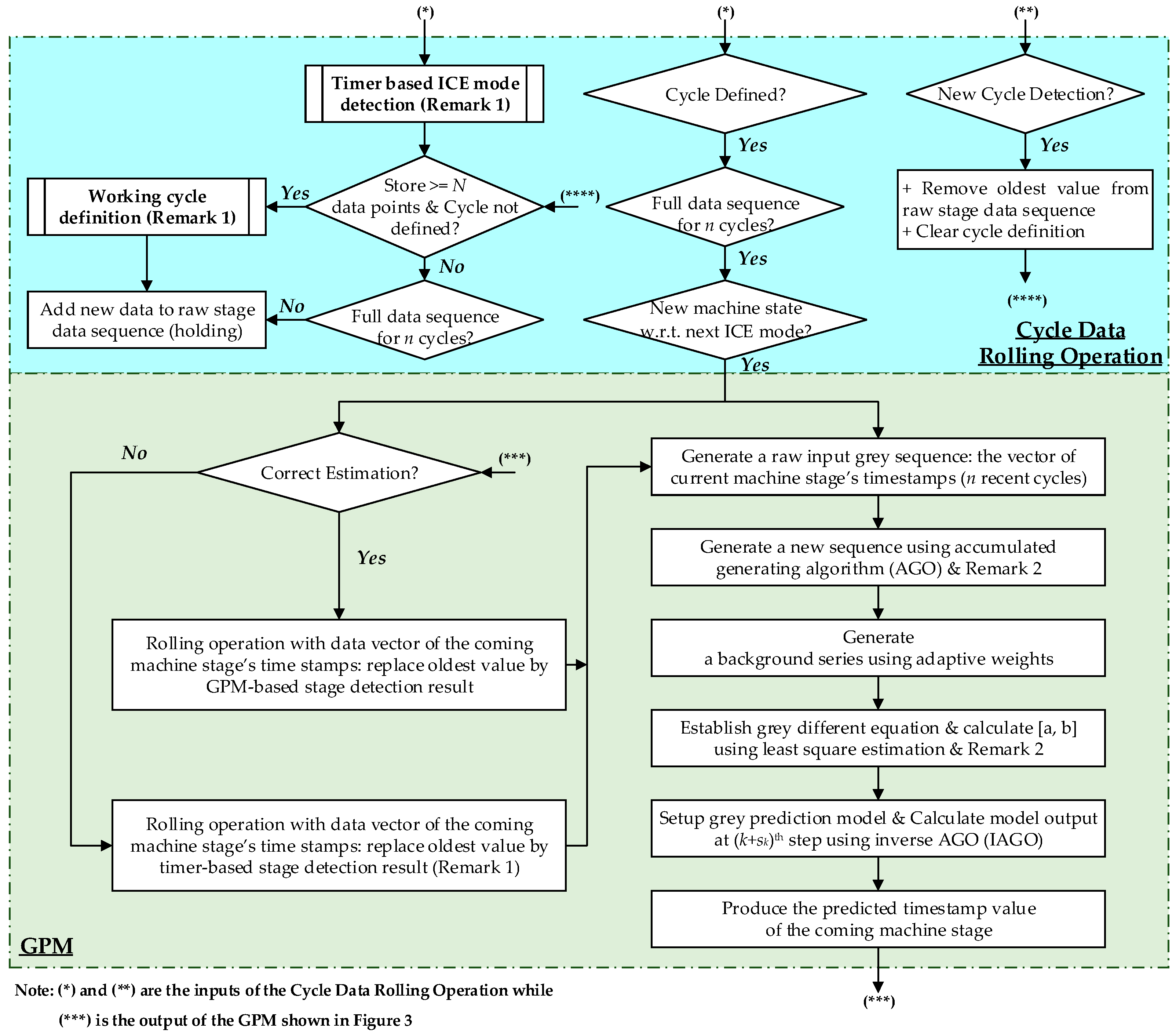
2.2.1. Cycle Data Rolling Operation
- A working cycle can be then identified by the iterative searching algorithm proposed in [12]. Once a periodic cycle is determined, the recorded machine stages are rearranged into a matrix form of cycle number, stages’ indices and timestamps within a cycle.
- For the cyclic operation, to estimate a coming machine stage (its index in the working cycle has been defined), a vector with n raw data points which are the timestamps of the same stage within n historical cycles is required.
- The GPM is only activated when the recorded stage matrix contains historical data of n cycles. If existing a new machine stage which is different from the defined stage sequence, the cycle definition is reset by removing the oldest machine stage and adding the newest one. The GPM is then de-activated and the search algorithm is applied again to identify the new working cycle.
2.2.2. Grey Prediction Model
2.2.3. Rule-Based Controller
- HMI (HMI flag) is a variable which is unit if there exists at least a signal sent from the HMI module, and is zero vice versa.
- TMR is value of the timer which counts number of continuous states of the engine which are within the same working mode, different from the current mode. This TMR is reset once having more than new engine states or a new engine mode is selected. is the pre-defined threshold value for TMR and, is the time in seconds needed to make a decision on ICE mode switching (in case the GPM is not activated). Here, is selected as 3.
- PRE is a variable representing a correct estimation of the GPM (if the estimation error is within a pre-defined acceptable range). Then, PRE = 1 if correct and PRE = 0 if not correct.
- IGN is a variable representing the engine state, IGN = 1 if ICE is on and IGN = 0 if ICE is off.
- SOC is the battery state of charge representing the energy remained in the battery (in percentage). In order to enable stop-start operation, this SOC should be greater than a minimum level SOCmin which allows the starter can crank the engine when STA mode is enabled. In this case, SOCmin is set to 70%.
- Rule for NOR mode: the ICE is shifted to NOR mode if:
- Rule for IDL mode: the ICE is shifted to IDL mode if:
- Rule for STO mode: the ICE is shifted to STO mode if:
- Rule for STA mode: the ICE is shifted to STA mode if:
3. HIL Platform for Real-Time Engine Controller Evaluation
3.1. Design Requirements and Specifications
- Rapid prototyping and validation of the engine control system for either traditional or hybrid (mainly micro/mild hybrid) propulsion mechanisms.
- Functional and non-functional testing of different ISS-based engine control schemes, such as timer-based ISSC and prediction-based ISSC.
- Rapid control prototyping tool chain: it is necessary to equip the HIL setup with a fast, efficient and flexible way of deploying, calibrating and validating of the developed control systems in a real-time environment. It also necessarily offers a re-use of plant models, control logics and data when moving between model-in-the loop (MIL) simulations and HIL experiments.
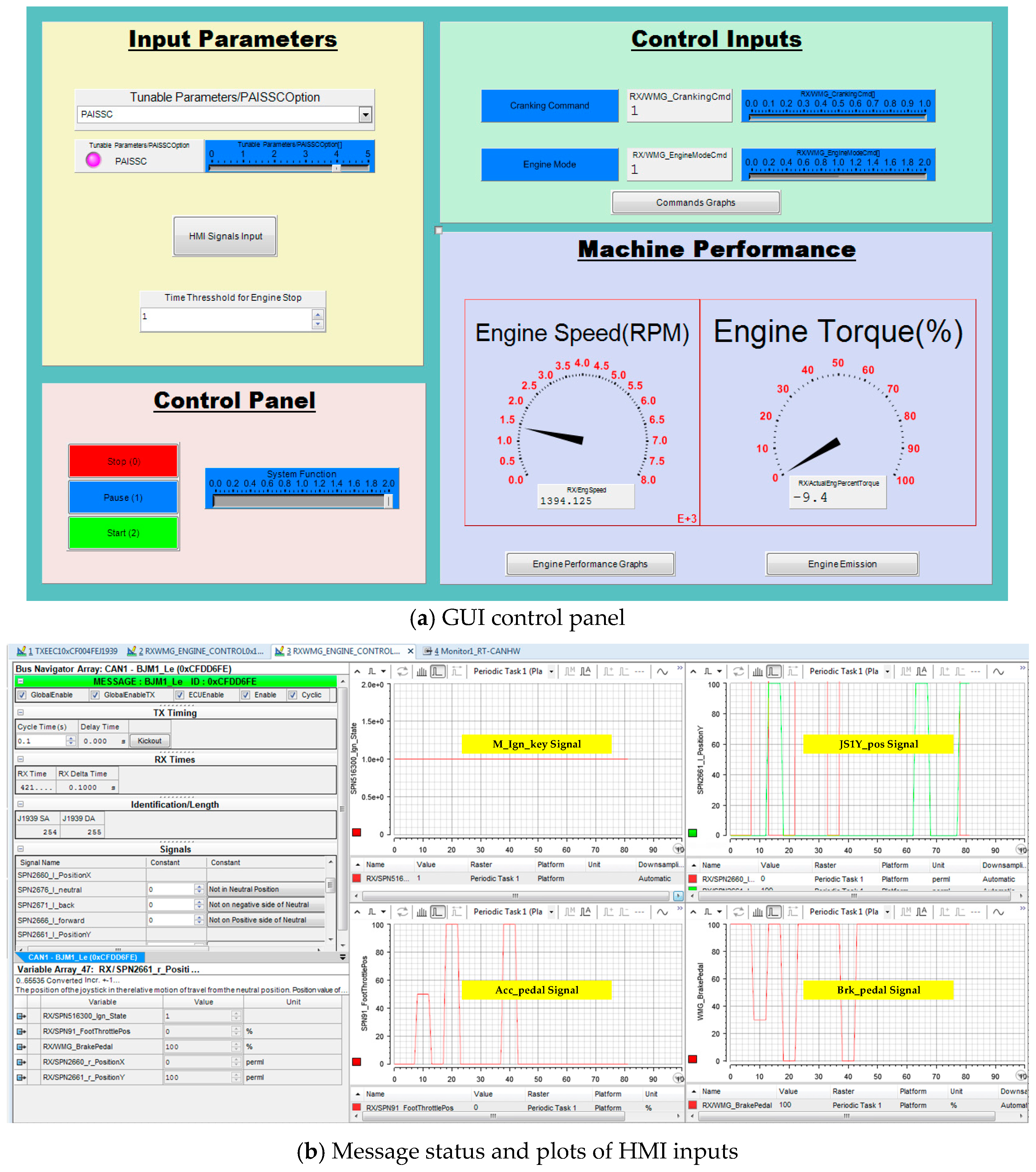
- A graphic user interface (GUI) is needed to allow control developers to interact with the HIL system easily. In addition, functions for automatically performing experiments and data acquisition are essential to minimize the development time and efforts. Therefore, the HIL should be equipped with proper rapid control prototyping (hardware and software) tool chains.
- Proper powertrain model for validation and analysis: in order to achieve reliable test results compared to the actual machine performance, it is required to use a high fidelity powertrain model which represents well the simulated system and is executable in real time to perform a closed-loop virtual reality environment.
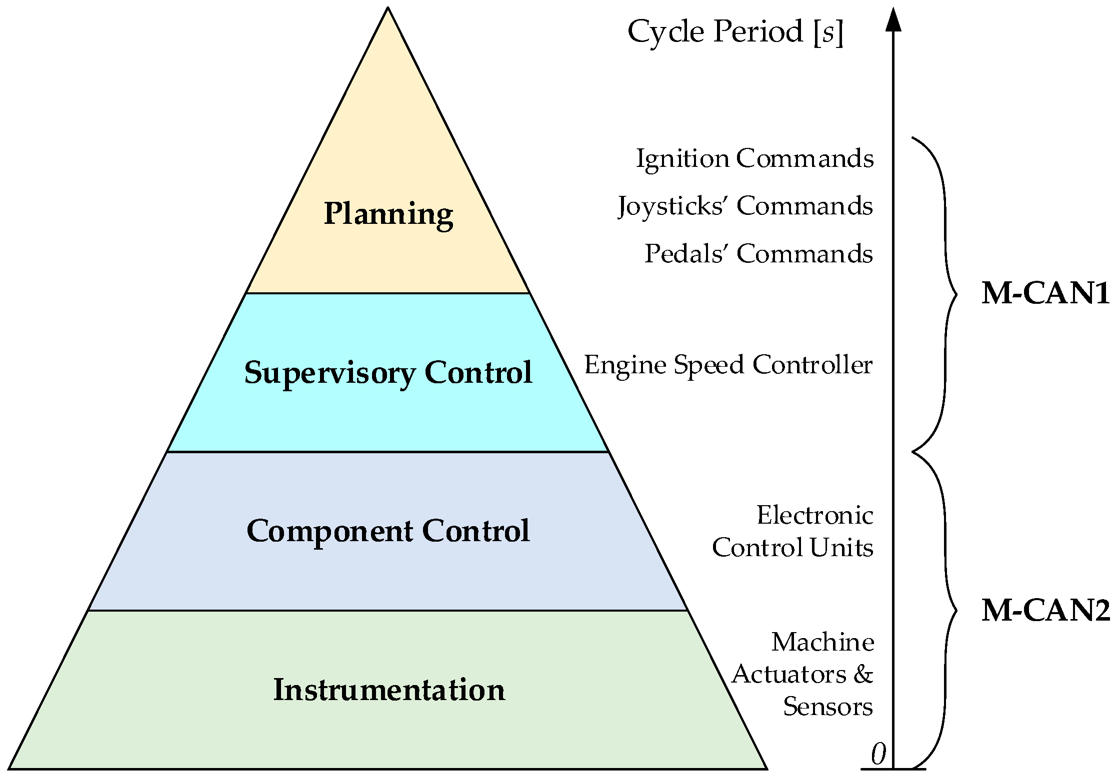
- Real-time communication: to investigate the capability of the ICE control methods in actual working conditions, a CAN bus interface needs to be used for the data interaction between the powertrain model and control systems.
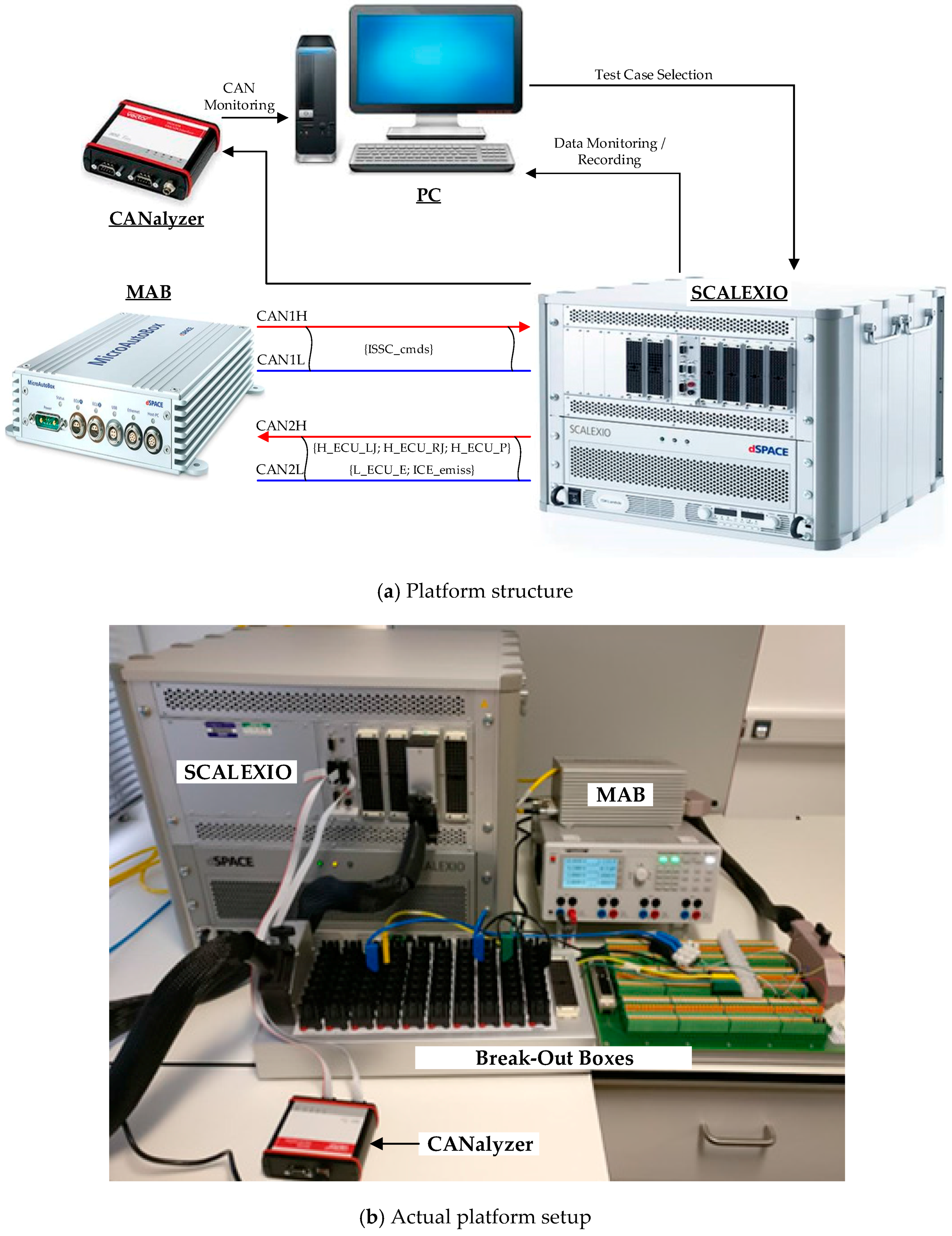
3.2. HIL Platform Design
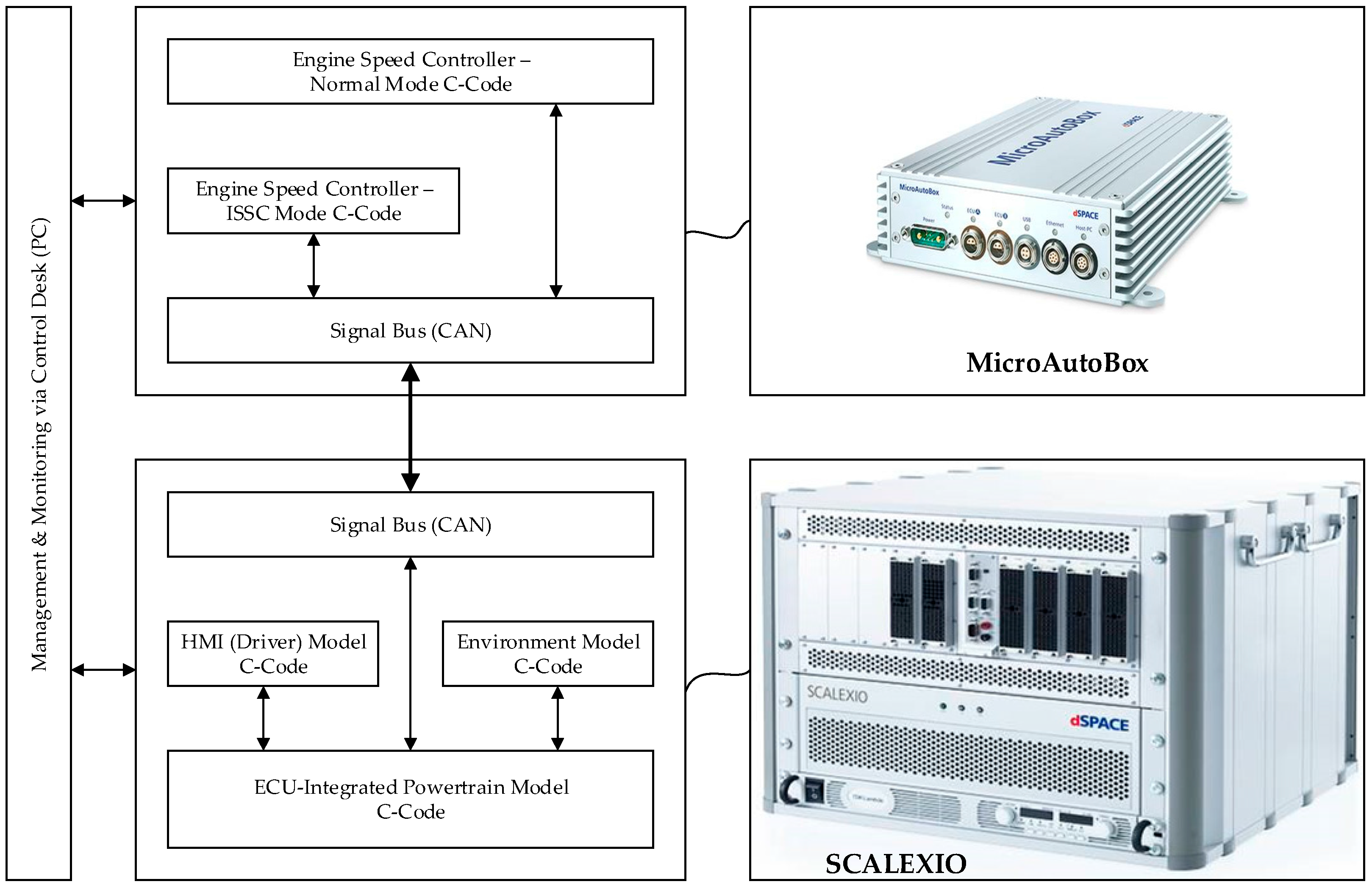
3.2.1. HIL Architecture
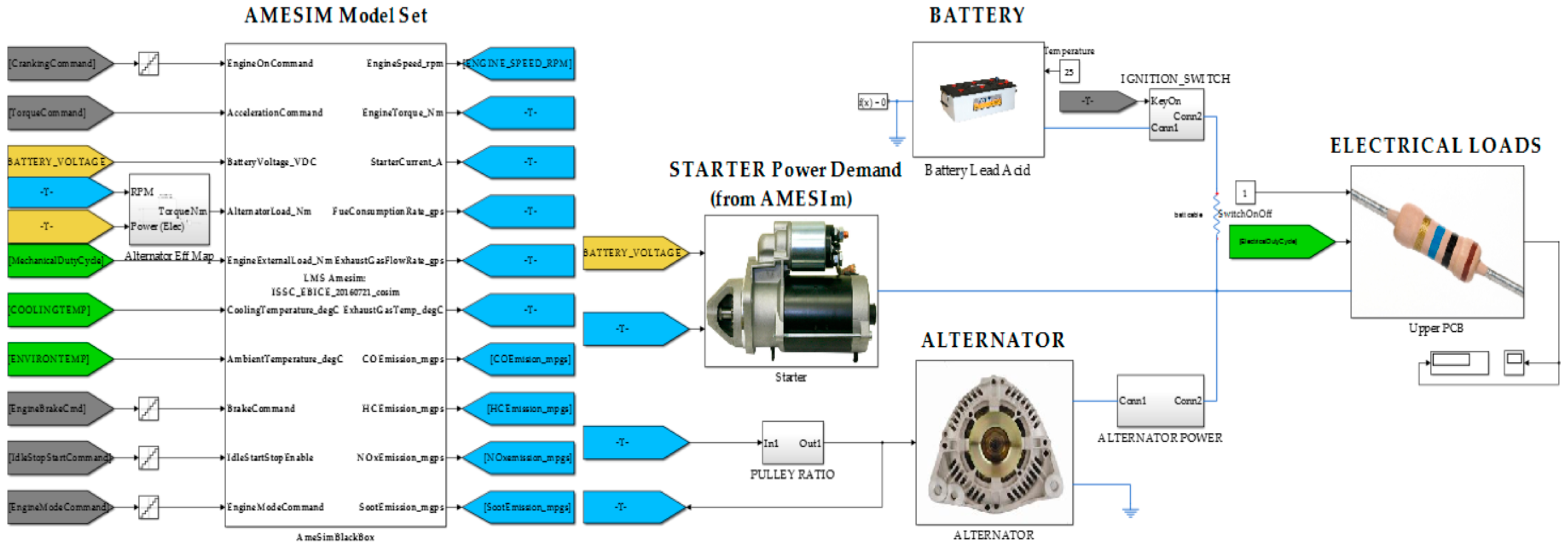
3.2.2. Real-Time Powertrain Model
3.2.3. CAN Interface
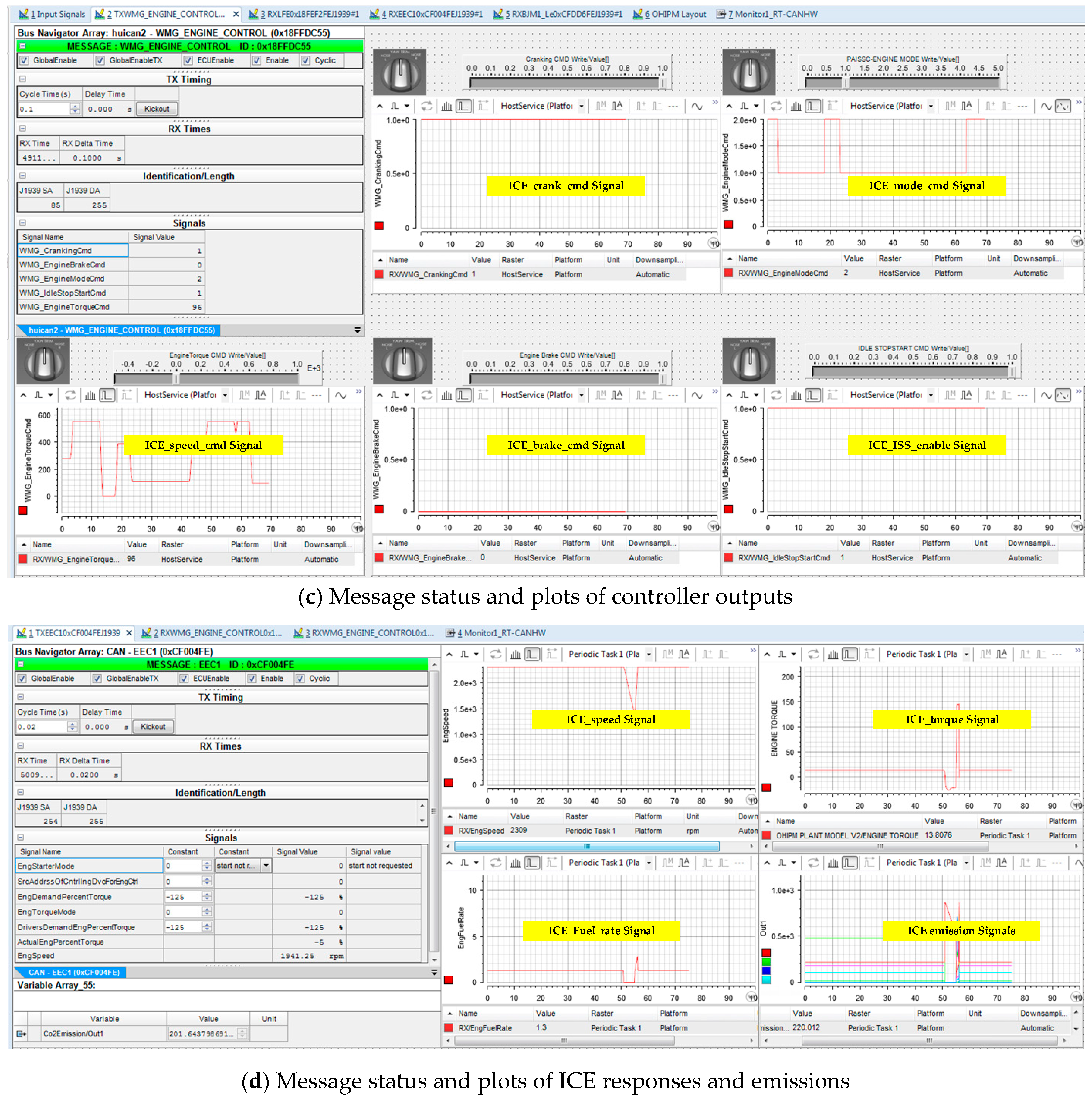
- The message called ISSC_cmds contains five signals which are sent to the ECU to drive the engine: ICE_crank_cmd, ICE_brake_cmd, ICE_ISS_enable, ICE_mode_cmd and ICE_speed_cmd.
- ICE_crank_cmd (0 or 1, 1-bit length): a rising edge from 0 to 1 will activate the starter and injectors to crank the engine from zero to idle speed or working speed; on the contrary, a falling edge from 1 to 0 will shut down the engine.
- ICE_brake_cmd (0 or 1, 1-bit length): a value of 1 will lock the engine shaft during the STO mode (ICE_crank_cmd = 0) and, vice versa.
- ICE_ISS_enable (0 or 1, 1-bit length): a value of 1 will active the ISS-based engine control mode and, vice versa.
- ICE_mode_cmd (0, 1 or 2, 2-bit length): the engine will run in NOR, IDL or STO mode if the value of ICE_mode_cmd is in turn 2, 1 or 0.
- ICE_speed_cmd (0 to 100, 8-bit length): the ICE torque command is computed using the following relation (please note that, value of 1 corresponds to the maximum speed command):where: JX1, JY1, JX2 and JY2 are in turn the signals from the two 2-axis joysticks (within range [0, 100], to drive the hydraulic actuators of the machine); AP and BP are in turn the signals of the acceleration and brake pedals (within range [0, 100], to control the machine traction).
3.2.4. HIL Platform
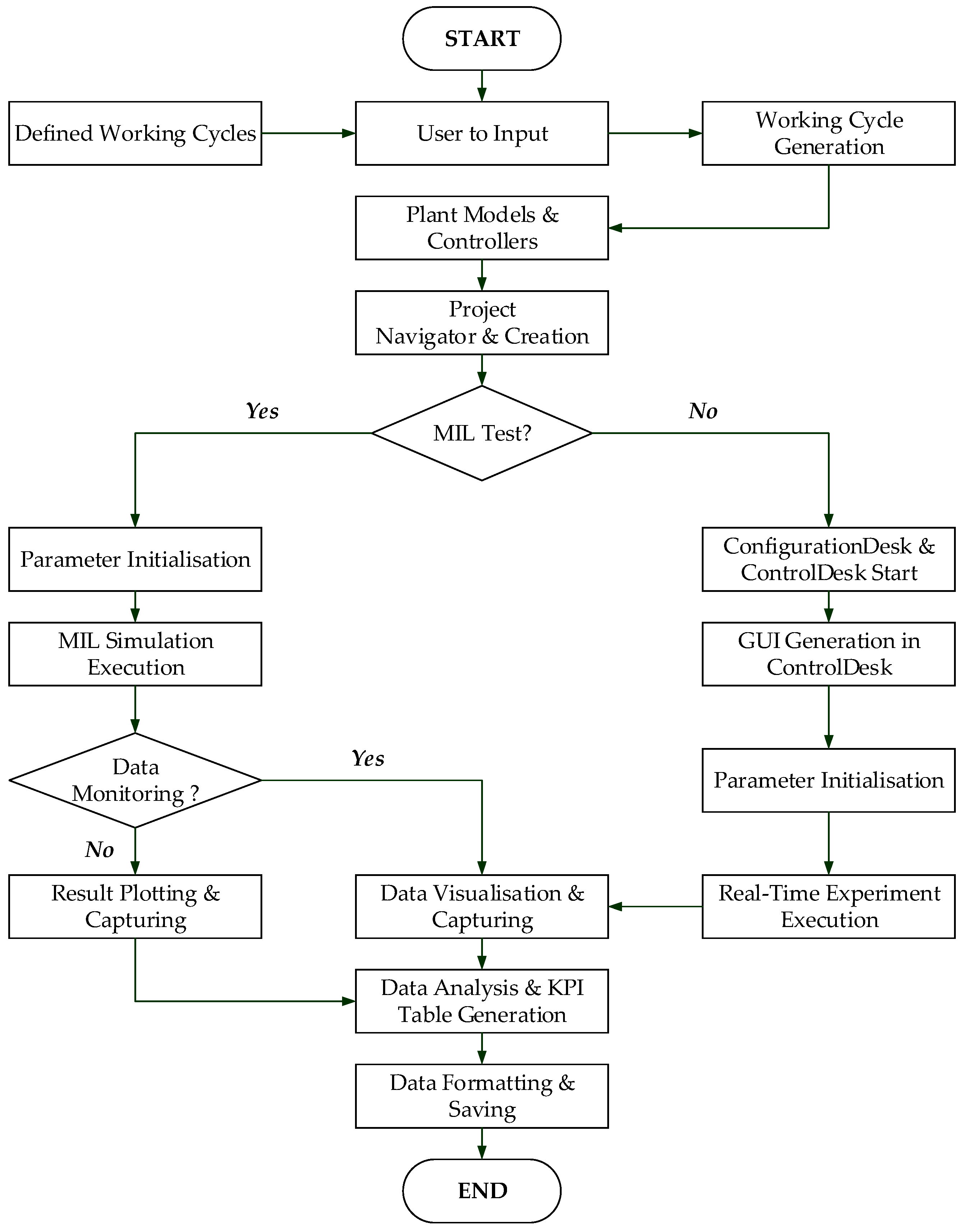
3.2.5. Simulation Tool Chain for MIL and HIL Testing
4. HIL Experiments and Analysis
4.1. Setup of Comparative ICE Speed Controllers and Test Case Definition
- The first test scenario: the defined cycle is used to create NC continuously and repeatedly working cycles. Here, the first three phases of the defined cycle are only executed one time as they represent the operator first time entering the machine to turn it on manually via the ignition key. The remained phases are then repeated NC times to perform the first test case with NC cycles (the phase number 18 of cycle n-th is connected to phase 4 of cycle (n + 1)-th). This scenario is utilized to investigate the differences between MIL results and real-time HIL results, and to compare the performance of the PISSC to the performances of the other control methods.
- The second test scenario: a set of NT new working cycles are randomly generated from the one defined in Table 4 and stored in additional NT excel files in such a way that their first three phases and the total cycle durations are the same while the other 15 phases, 4 to 18 (or row 5th to row 19th in Table 4), are randomly mixed for different sequences with different phases’ durations. These new cycles are then employed to construct NT corresponding test cases based on the same principle as the first scenario. This scenario is utilized to assessing the energy/emission saving capability of the proposed ICE control approach in different conditions.
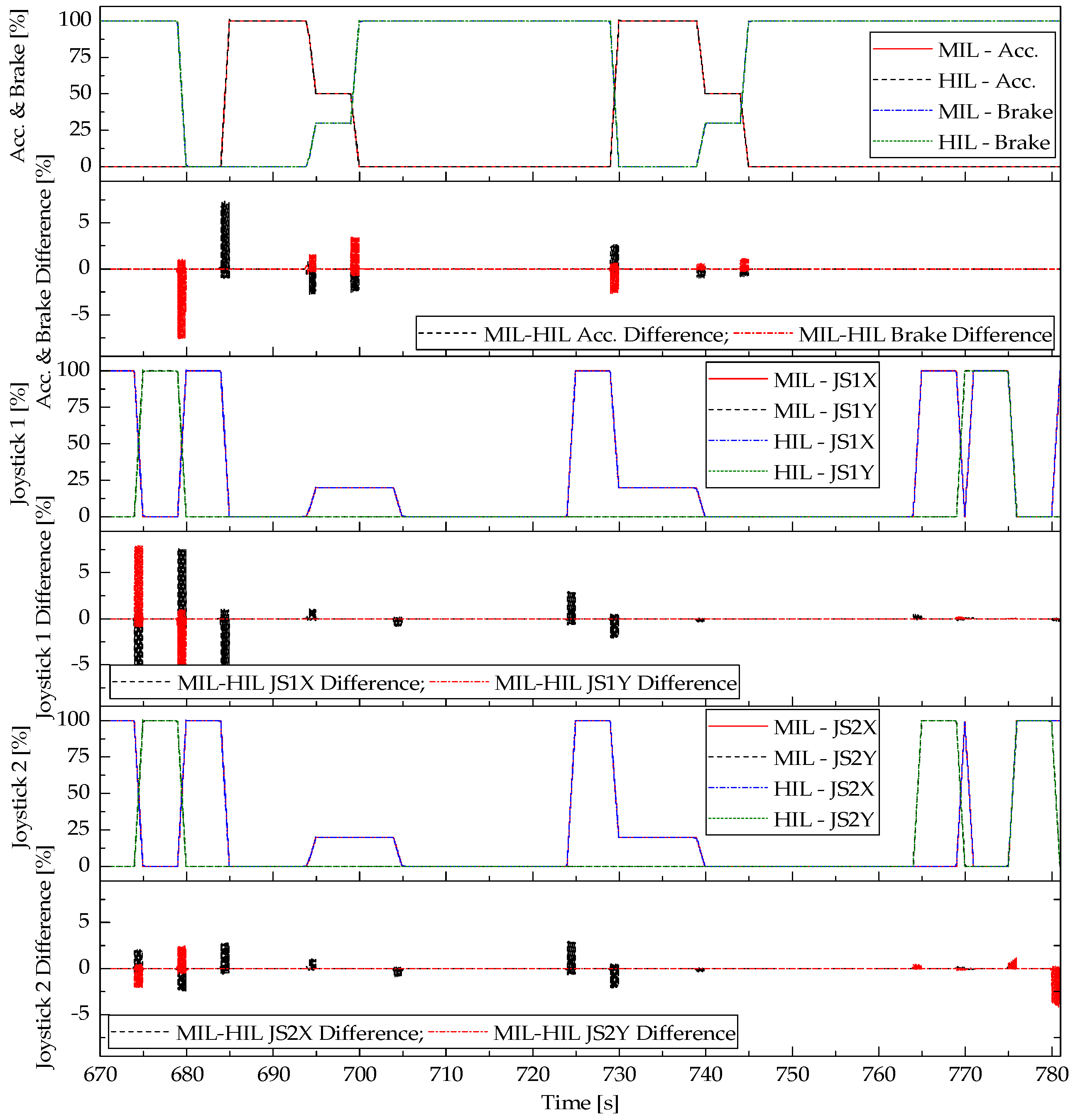
4.2. Correlation between MIL and HIL Results
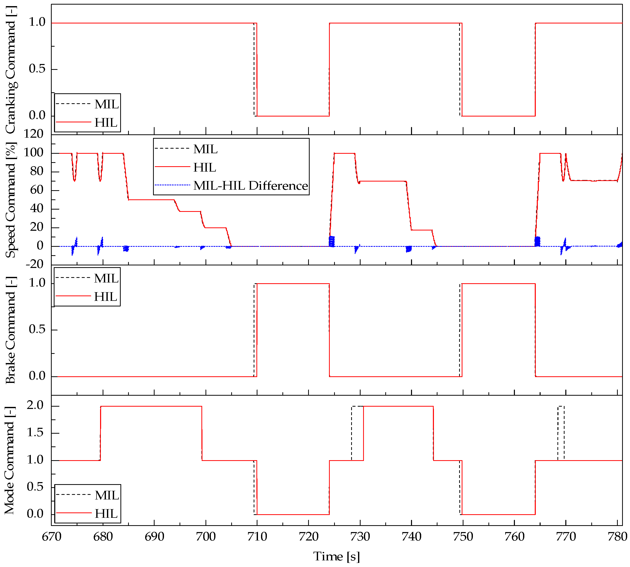
4.2.1. PISSC Outputs Correlation
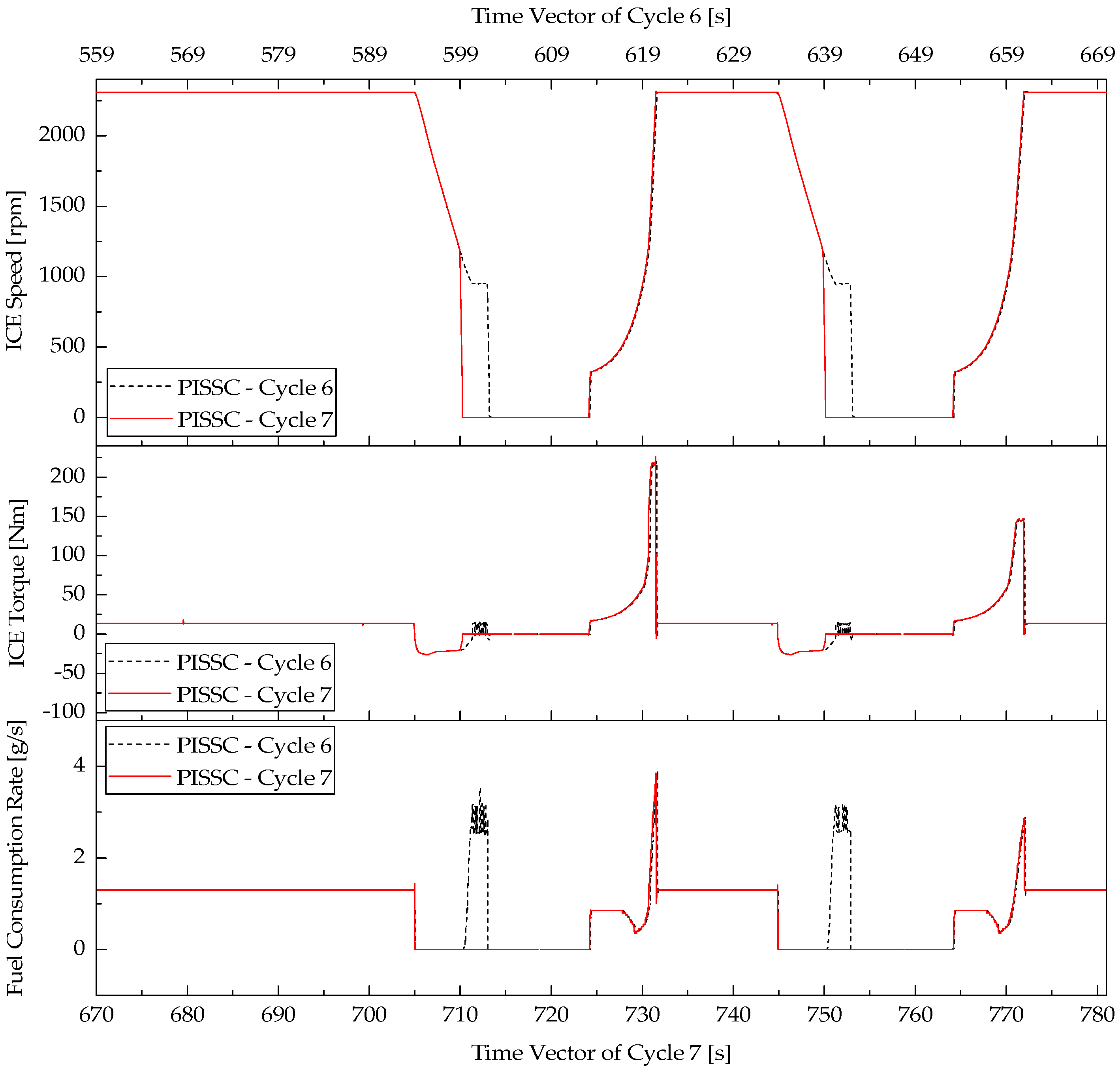
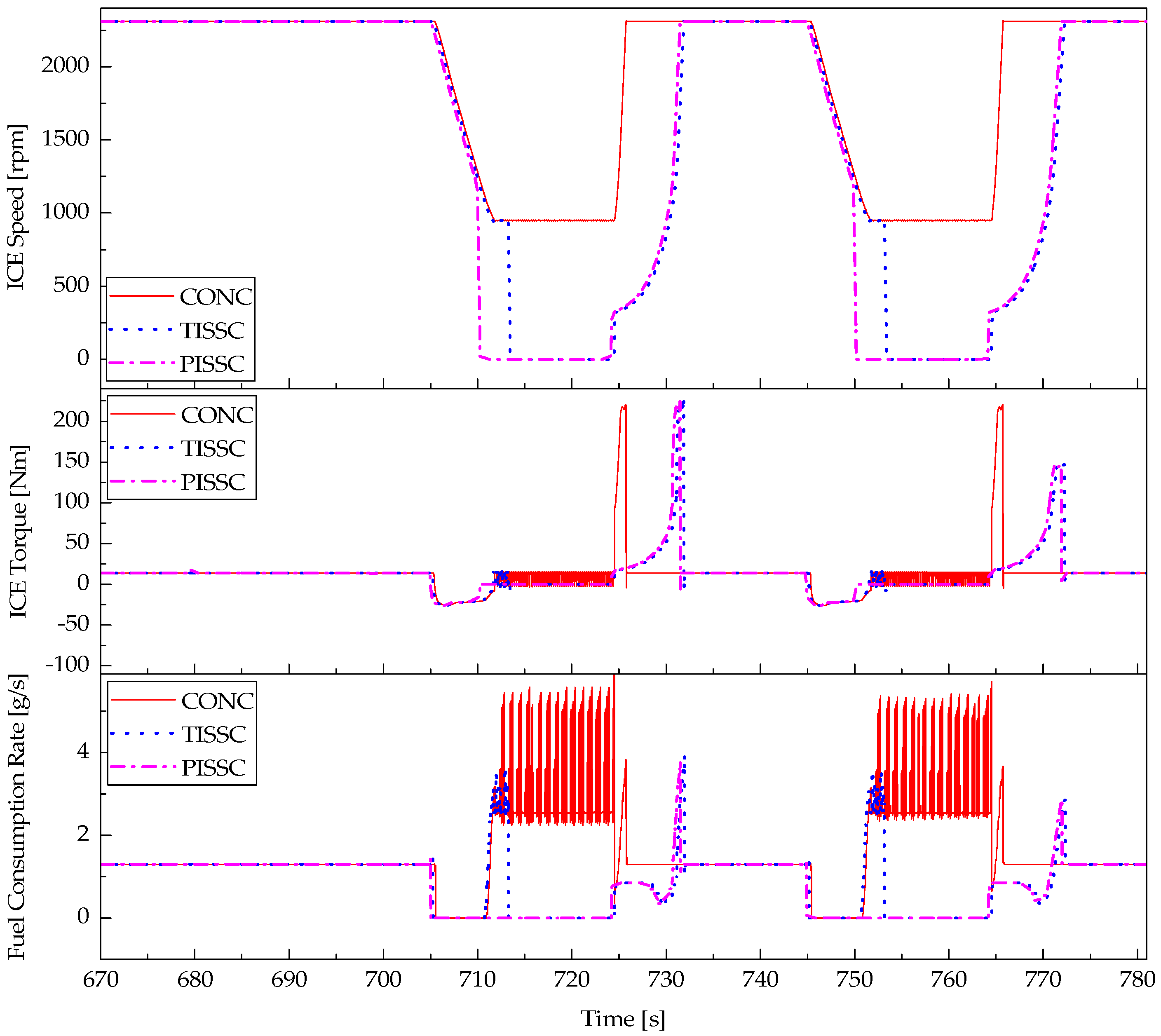
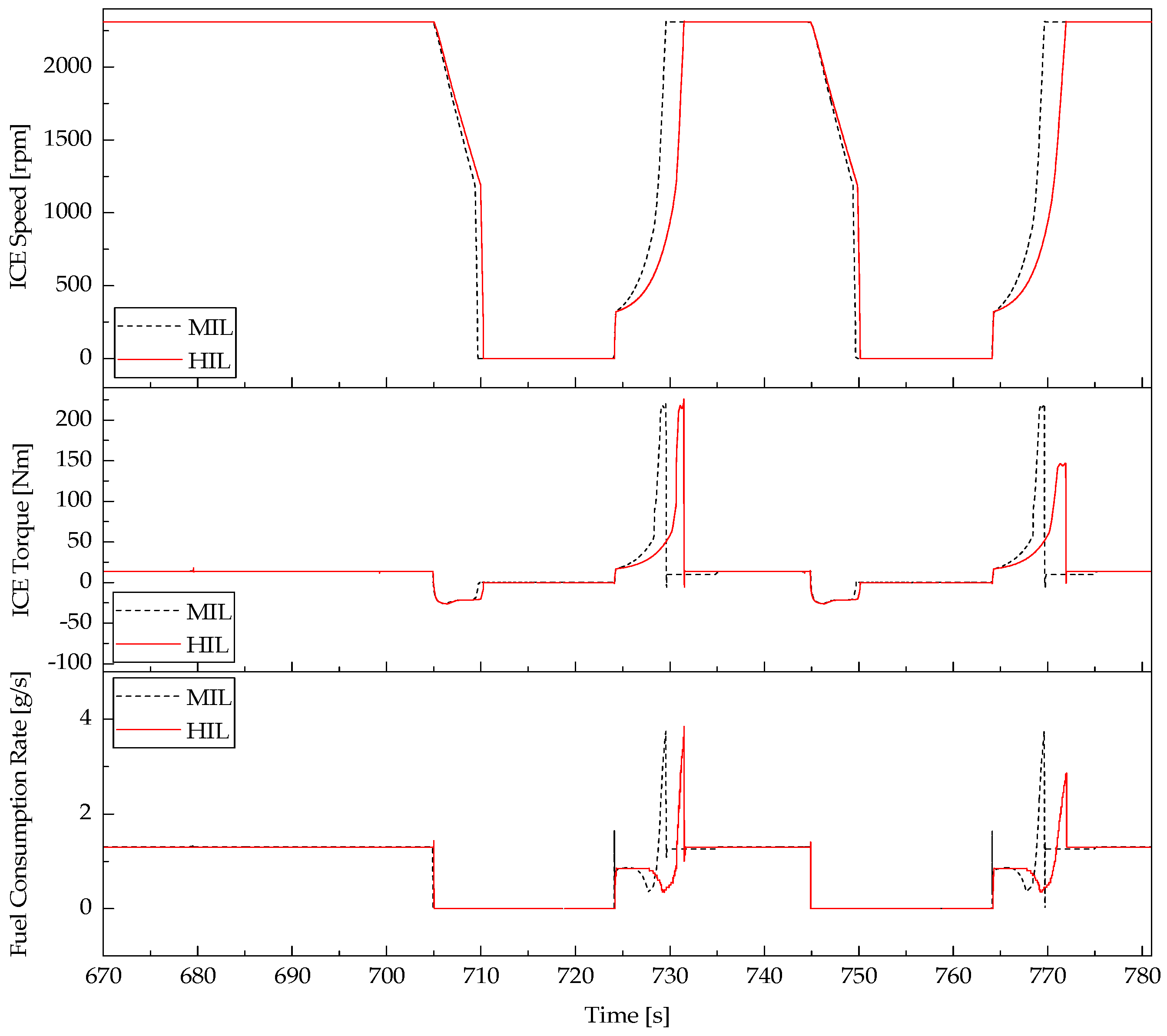
4.2.2. ICE Dynamics Correlation
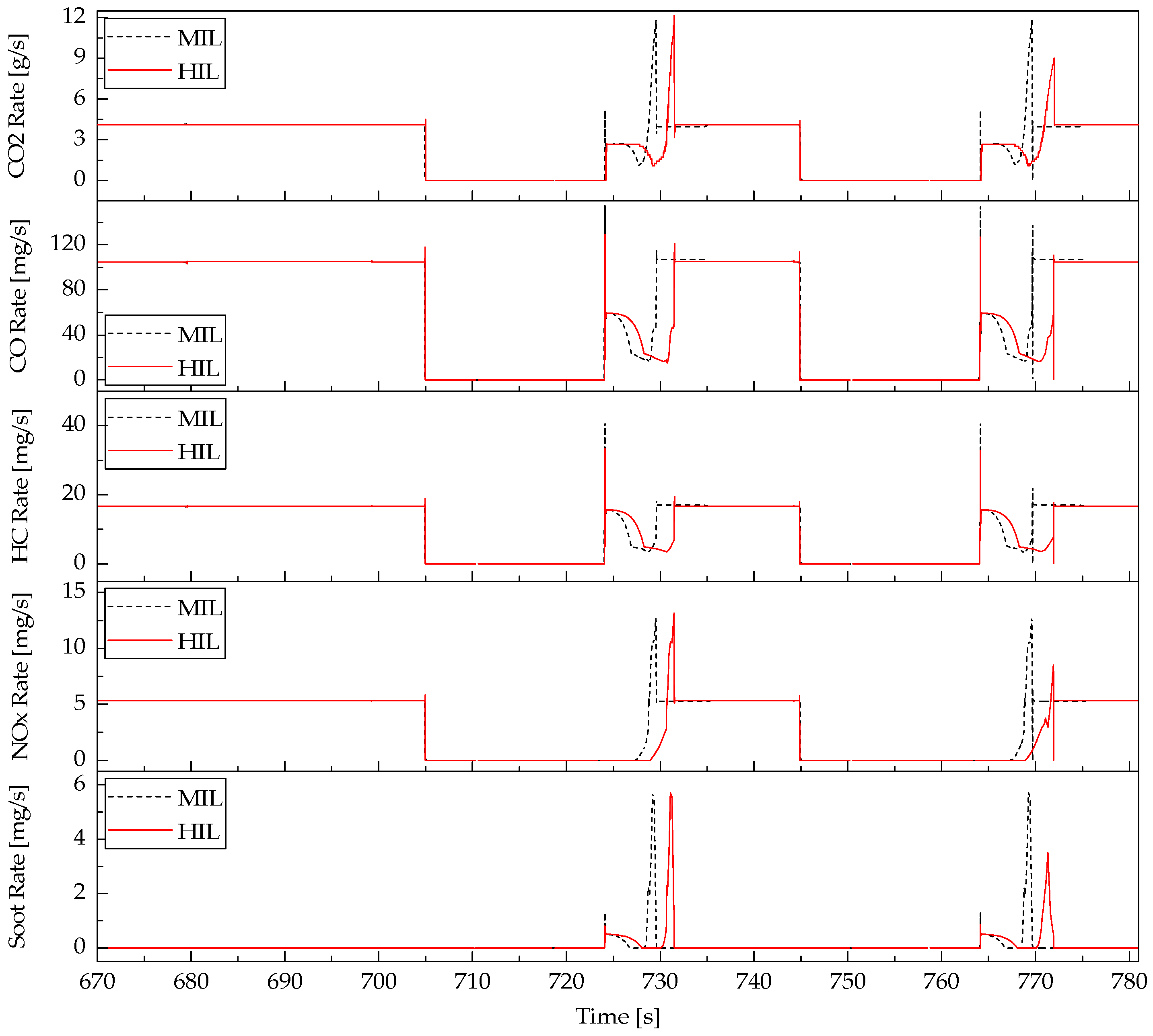
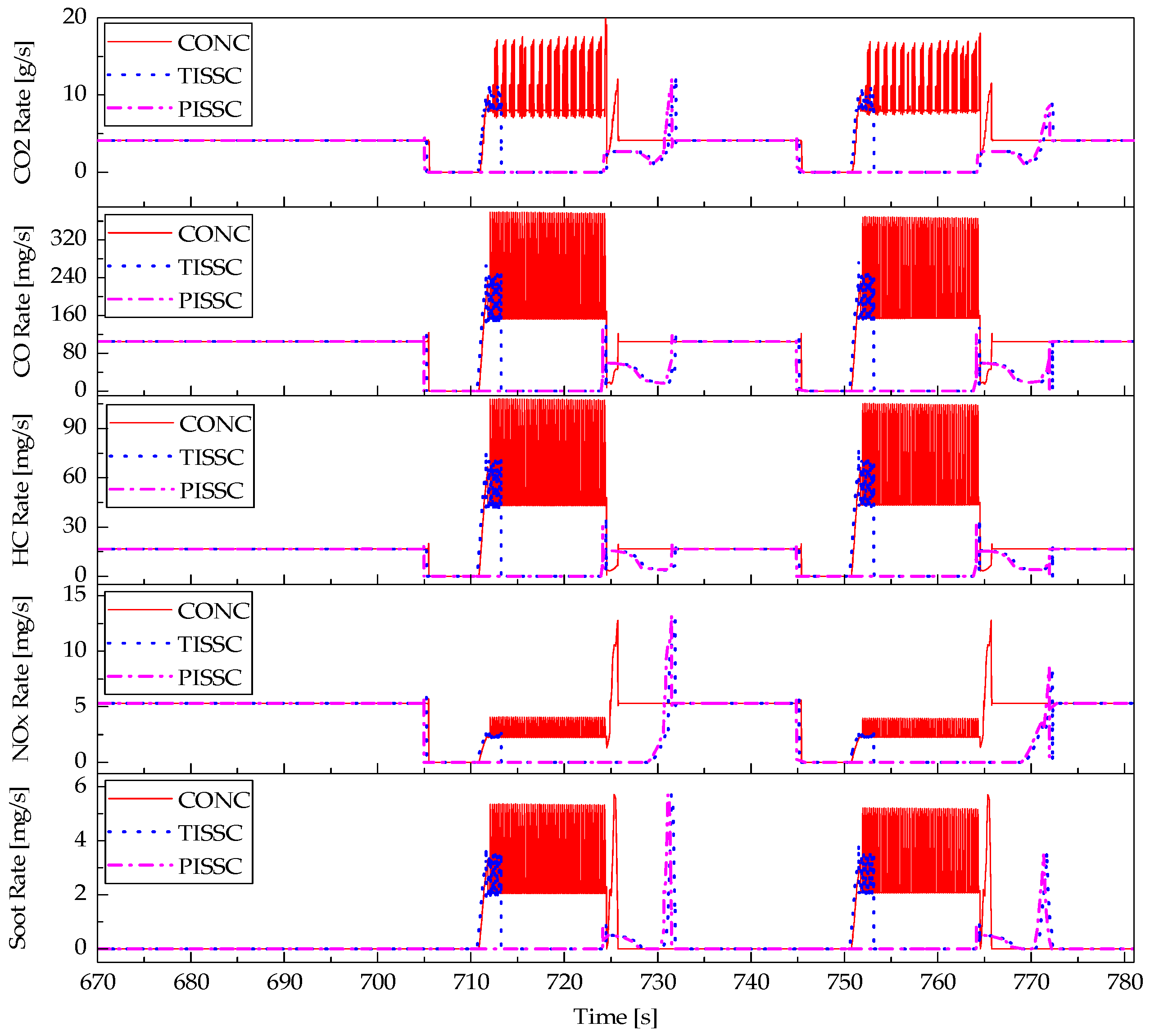
4.2.3. ICE Emissions’ Rates Correlation
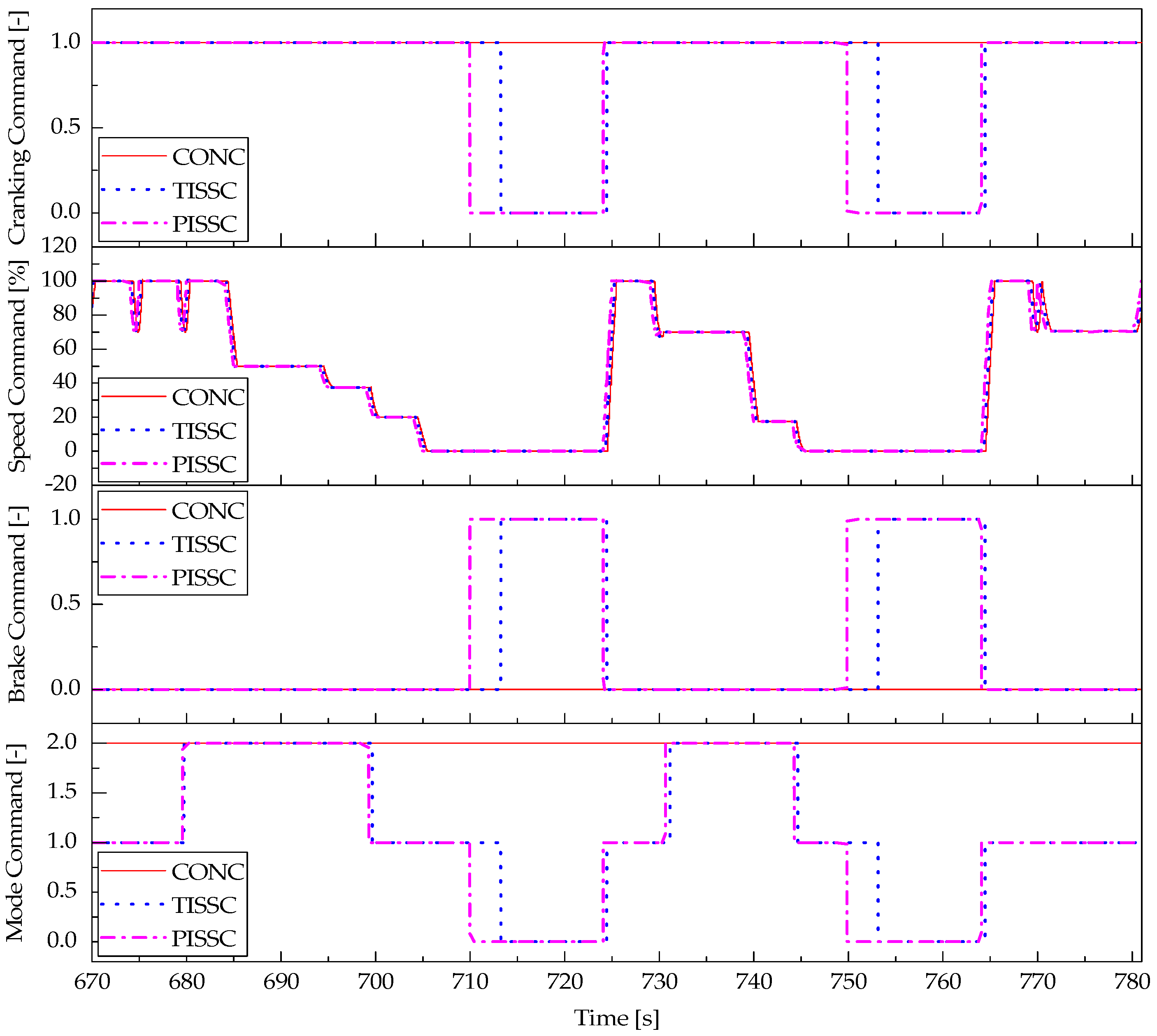
4.3. Comparison of ICE Performances Using Different Controllers
4.4. Analysis on Fuel and Emission Saving Potential
5. Conclusions
Acknowledgments
Author Contributions
Conflicts of Interest
References
- Sharrard, A.L.; Matthews, H.S.; Roth, M. Environmental implications of construction site energy use and electricity generation. J. Constr. Eng. Manag. 2007, 133, 846–854. [Google Scholar] [CrossRef]
- Albers, J.; Meissner, E.; Shirazi, S. Lead-acid batteries in micro-hybrid vehicles. J. Power Sour. 2011, 196, 3993–4002. [Google Scholar] [CrossRef]
- Canova, M.; Guezennec, Y.; Yurkovich, S. On the control of engine start/stop dynamics in a hybrid electric vehicle. J. Dyn. Syst. Meas. Control 2009, 131, 061005. [Google Scholar] [CrossRef]
- Fontaine, C.; Delprat, S.; Guerra, T.M.; Paganelli, S.; Duguey, J.F. Improving micro hybrid vehicles performances with the maximum principle. In Proceedings of the 18th World Congress. The International Federation of Automatic Control, Milan, Italy, 28 August–2 September 2011. [Google Scholar]
- Ozdemir, A.; Mugan, A. Stop-start system integration to diesel engine and system modelling and validation. IFAC Proc. Vol. 2013, 46, 95–100. [Google Scholar] [CrossRef]
- Rafiei, A.; Ghodsi, M.; Al-Yahmedi, A. Smart stop-start strategy for Samand micro-hybrid based on traffic qualification. In Proceedings of the 24th Iranian Conference on Electrical Engineering (ICEE), Shiraz, Iran, 10–12 May 2016; pp. 1187–1192. [Google Scholar]
- Rizoug, N.; Feld, G.; Bouhali, O.; Mesbahi, T. Micro-hybrid vehicle supplied by a multi-source storage system (battery and supercapacitors): Optimal power management. In Proceedings of the 7th IET International Conference on Power Electronics, Machines and Drives (PEMD), Manchester, UK, 8–10 April 2014; pp. 1–5. [Google Scholar]
- Schaeck, S.; Stoermer, A.O.; Hockgeiger, E. Micro-hybrid electric vehicle application of valve-regulated lead-acid batteries in absorbent glass mat technology: Testing a partial-state-of-charge operation strategy. J. Power Sources 2009, 190, 173–183. [Google Scholar] [CrossRef]
- Dinh, T.Q.; Marco, J.; Greenwood, D.; Harper, L.; Corrochano, D. Powertrain modelling for engine stop-start dynamics and control of micro/mild hybrid construction machines. Proc. Inst. Mach. Eng. Part K J. Multi-Body Dyn. 2017, in press. [Google Scholar] [CrossRef]
- Frellch, T.A.; Michael, S. Auto Adaptive Engine Idle Speed Control. U.S. Patent 2014/0053801 A1, 27 February 2014. [Google Scholar]
- Park, K.S.; Kim, S.I.; Jeong, H.J. Low Idle Control System of Construction Equipment and Automatic Control Method Thereof. U.S. Patent 2013/0289834 A1, 31 October 2013. [Google Scholar]
- Dinh, T.Q.; Marco, J.; Niu, H.; Greenwood, D.; Harper, L.; Corrochano, D. A novel method for idle-stop-start control of micro hybrid construction equipment—Part A: Fundamental concepts and design. Energies 2017, 10, 962. [Google Scholar] [CrossRef]
- Himmler, A.; Lamberg, K.; Beine, M. Hardware-in-the-loop testing in the context of ISO 26262. In Proceedings of the SAE 2012 World Congress & Exhibition, Detroit, MI, USA, 24–26 April 2012. [Google Scholar]
- Yi, L.; He, H.; Peng, J. Hardware-in-loop simulation for the energy management system development of a plug-in hybrid electric bus. Energy Procedia 2016, 88, 950–956. [Google Scholar] [CrossRef]
- Adenmark, M.; Deter, M.; Schulte, T. Testing networked ECUS in a HIL based integration lab. In Proceedings of the SAE 2006 Commercial Vehicle Engineering Congress & Exhibition, Rosemont, CA, USA, 31 October–2 November 2006. [Google Scholar]
- Kluge, T.; Allen, J.; Dhaliwal, A. Advantages and challenges of closed-loop HIL testing for commercial and off-highway vehicles. In Proceedings of the SAE 2009 Commercial Vehicle Engineering Congress & Exhibition, Detroit, MI, USA, 6–7 October 2009. [Google Scholar]
- Dinh, T.Q.; Ahn, K.K. An accurate signal estimator using a novel smart adaptive grey model SAGM (1, 1). Expert Syst. Appl. 2012, 39, 7611–7620. [Google Scholar]
- Dinh, T.Q.; Ahn, K.K.; Nguyen, T.T. Design of an advanced time delay measurement and a smart adaptive unequal interval grey predictor for real-time nonlinear control systems. IEEE Trans. Ind. Electron. 2013, 60, 4574–4589. [Google Scholar]
- Geng, N.; Zhang, Y.; Sun, Y.; Jiang, Y.; Chen, D. Forecasting China’s annual biofuel production using an improved grey model. Energies 2015, 8, 12080–12099. [Google Scholar] [CrossRef]
- Kim, D.; Goh, T.; Park, M.; Kim, S. Fuzzy sliding mode observer with grey prediction for the estimation of the state-of-charge of a lithium-ion battery. Energies 2015, 8, 12409–12428. [Google Scholar] [CrossRef]
- Zeng, F.; Cheng, X.; Guo, J.; Tao, L.; Chen, Z. Hybridising human judgment, AHP, grey theory, and fuzzy expert systems for candidate well selection in fractured reservoirs. Energies 2017, 10, 447. [Google Scholar] [CrossRef]
- Deng, J.L. Control problem of grey system. Syst. Control Lett. 1982, 1, 288–294. [Google Scholar]
- Costlow, T. Standards Step Forward in Design of Off-Highway Electronics. Available online: http://www.sae.org.cn/uploads/pubs/magazines/OHW/15OFHP10.pdf (accessed on 10 January 2017).
- Han, Z.; Uludogan, A.; Hampson, G.J.; Reitz, R.D. Mechanism of soot and NOx emission reduction using multiple-injection in a diesel engine. In Proceedings of the SAE International Congress & Exposition, Detroit, MI, USA, 26–29 February 1996. [Google Scholar]
- Truitt, P. EPA guidelines. In Potential for Reducing Greenhouse Gas Emissions in the Construction Sector, U.S.; Environmental Protection Agency: Washington, DC, USA, 2009. [Google Scholar]


| Component | Specifications |
|---|---|
| Belt transmission | Transmission ratio 2.8:1 |
| Pinion-ring gear transmission | Transmission ratio 11:1 |
| Flywheel mass 44.7 kg | |
| Engine | Four-stroke diesel engine 1.9 L |
| Max speed 2400 rpm | |
| Gross power 41 kW, net power 38.4 kW | |
| Compression ratio 16.7:1 | |
| Starter | 12 V working voltage |
| 2 kW power | |
| Alternator | Current 80 A |
| Battery | Lead-acid battery |
| 12 V nominal voltage | |
| 75 Ah capacity |
| Message Name | Signal Name | Signal Range (-) | Resolution (bit) | Cycle Period (ms) | Signal Mean | Physical Range & Unit |
|---|---|---|---|---|---|---|
| M-CAN1 | ||||||
| Display | M_Ign_key | 0/1/2 | 2 | 500 | Ignition key | 0/1/2 |
| H_ECU_LJ | JS1X_pos | 0–100 | 8 | 100 | Joystick 1 X angle percent | 0–100% |
| JS1Y_pos | 0–100 | 8 | 100 | Joystick 1 Y angle percent | 0–100% | |
| H_ECU_RJ | JS2X_pos | 0–100 | 8 | 100 | Joystick 2 X angle percent | 0–100% |
| JS2Y_pos | 0–100 | 8 | 100 | Joystick 2 Y angle percent | 0–100% | |
| H_ECU_P | Acc_pedal | 0–100 | 8 | 100 | Acceleration pedal angle percent | 0–100% |
| Brk_pedal | 0–100 | 8 | 100 | Brake pedal angle percent | 0–100% | |
| ISSC_cmds | ICE_crank_cmd | 0/1 | 1 | 100 | ICE cranking command | 0/1 |
| ICE_brake_cmd | 0/1 | 1 | 100 | ICE brake command | 0/1 | |
| ICE_ISS_enable | 0/1 | 1 | 100 | ISS control enable | 0/1 | |
| ICE_mode_cmd | 0/1/2 | 2 | 100 | ICE mode command | 0/1/2 | |
| ICE_speed_cmd | 0–100 | 8 | 100 | ICE speed command percent | 0–100% | |
| M-CAN2 | ||||||
| L_ECU_E | ICE_speed | 0–8032 | 16 | 20 | ICE speed response | 0–8032 rpm |
| L_ECU_E | ICE_torque | 0–100 | 8 | 20 | ICE torque response in percent | 0–100% |
| L_ECU_E | ICE_Fuel_rate | 0–100 | 16 | 20 | ICE fuel consumption rate | 0–100 g/s |
| ICE_emiss | ICE_Emis_CO2 | 0–350 | 8 | 20 | ICE CO2 emission | 0–350 g/s |
| ICE_Emis_CO | 0–350 | 8 | 20 | ICE CO emission | 0–350 mg/s | |
| ICE_Emis_HC | 0–350 | 8 | 20 | ICE HC emission | 0–350 mg/s | |
| ICE_Emis_NOx | 0–350 | 8 | 20 | ICE NOx emission | 0–350 mg/s | |
| ICE_Emis_Soot | 0–350 | 8 | 20 | ICE Soot emission | 0–350 mg/s | |
| Controller Name | Controller Meaning | Working Modes | Algorithm | |||
|---|---|---|---|---|---|---|
| Normal | Idle | Stop | Start | |||
| CONC | Conventional controller | √ | - | - | - | Traditional logics without ISS |
| TISSC | Timer-based ISS controller | √ | √ | √ | √ | Timer-based logics |
| PISSC | Prediction-based ISS controller | √ | √ | √ | √ | Prediction-based logics |
| Phase No. | Phase Time Stamp (s) | Machine Key 1 | Mech Load 2 M (%) | Elec Load 3 E (%) | JX1 (%) | JX2 (%) | JY1 (%) | JY2 (%) | AP (%) | BP (%) |
|---|---|---|---|---|---|---|---|---|---|---|
| 1 | 0.01 | 0 | 0 | 0 | 0 | 0 | 0 | 0 | 0 | 0 |
| 2 | 3 | 1 | 0 | 100 | 0 | 0 | 0 | 0 | 0 | 0 |
| 3 | 4 | 2 | 0 | 100 | 0 | 0 | 0 | 0 | 0 | 0 |
| 4 | 5 | 1 | 50 | 100 | 100 | 0 | 100 | 0 | 0 | 100 |
| 5 | 10 | 1 | 50 | 100 | 0 | 100 | 0 | 100 | 0 | 100 |
| 6 | 15 | 1 | 50 | 100 | 100 | 100 | 0 | 0 | 0 | 100 |
| 7 | 20 | 1 | 50 | 100 | 0 | 0 | 100 | 100 | 0 | 100 |
| 8 | 25 | 1 | 50 | 100 | 100 | 100 | 0 | 0 | 0 | 0 |
| 9 | 30 | 1 | 100 | 100 | 0 | 0 | 0 | 0 | 100 | 0 |
| 10 | 40 | 1 | 100 | 100 | 20 | 20 | 0 | 0 | 50 | 30 |
| 11 | 45 | 1 | 50 | 100 | 20 | 20 | 0 | 0 | 0 | 100 |
| 12 | 50 | 1 | 0 | 100 | 0 | 0 | 0 | 0 | 0 | 100 |
| 13 | 70 | 1 | 20 | 100 | 100 | 100 | 0 | 0 | 0 | 100 |
| 14 | 75 | 1 | 20 | 100 | 20 | 20 | 0 | 0 | 100 | 0 |
| 15 | 85 | 1 | 20 | 100 | 0 | 0 | 0 | 0 | 50 | 30 |
| 16 | 90 | 1 | 0 | 100 | 0 | 0 | 0 | 0 | 0 | 100 |
| 17 | 110 | 1 | 20 | 100 | 100 | 0 | 0 | 100 | 0 | 100 |
| 18 | 115 | 1 | 50 | 100 | 0 | 100 | 100 | 0 | 0 | 100 |
| Factor | Factor’s Unit | MIL Test | HIL Test | Average Difference between MIL and HIL |
|---|---|---|---|---|
| HMI commands | % | Followed commands | Followed commands | 0.699% (RMSE) |
| ICE cranking command | % | Followed command | Followed command | 0.101% (RMSE) |
| ICE spee command | % | Followed command | Followed command | 1.428% (RMSE) |
| ICE brake command | % | Followed command | Followed command | 0.101% (RMSE) |
| ICE mode command | % | Followed command | Followed command | 0.209% (RMSE) |
| ICE speed | rpm | Faster response | Slower response | 268.273 rpm (RSME) |
| ICE torque | Nm | Faster response | Slower response | 31.021 Nm (RSME) |
| Total fuel consumption | L | 1.617 | 1.577 | 2.448% (Relative) |
| Total CO2 | g | 4237.597 | 4133.869 | 2.448% (Relative) |
| Total CO | mg | 100,858.124 | 97,109.689 | 3.717%(Relative) |
| Total HC | mg | 17,099.2 | 16,764.519 | 1.957% (Relative) |
| Total NOx | mg | 48,62.868 | 4537.388 | 6.693% (Relative) |
| Total Soot | mg | 189.162 | 193.336 | −2.206% (Relative) |
| KPI | KPI’s Unit | CONC | TISSC | PISSC | Notes |
|---|---|---|---|---|---|
| Stop count | - | 1 | 29 | 29 | Include initial state of ICE |
| Start count | - | 0 | 28 | 28 | Not include 1st ICE start using key |
| Run time | s | 1553.870 | 1243.780 | 1197.600 | Total ICE run time |
| Stop time | s | 0.140 | 310.230 | 356.410 | Total ICE stop time |
| Fuel used | L (Litres) | 4.790 | 1.680 | 1.577 | Total fuel consumed by ICE |
| Fuel saved | L | 0 | 0.329 | 0.378 | Against no stop-start function |
| Total fuel saved | L | 0 | 3.111 | 3.213 | Against CONC’s total fuel used |
| % Total fuel saved | % | 0 | 64.939 | 67.073 | Against CONC’s total fuel used |
| % Total fuel saved 2 | % | 0 | 0 | 20.974 | Against TISSC’s total fuel used |
| Fuel cost used | £ (Pound 1) | 5.557 | 1.948 | 1.830 | Total fuel cost for ICE fuel usage |
| Fuel cost saved | £ | 0 | 0.382 | 0.439 | Against no stop-start function |
| Total fuel cost saved | £ | 0 | 3.609 | 3.727 | Against CONC’s total fuel cost |
| Total fuel cost saved 2 | £ | 0 | 0 | 0.118 | Against TISSC’s total fuel cost |
| CO2 emission | g | 12,554.780 | 4401.885 | 4133.869 | Total ICE CO2 emission |
| CO2 emission reduced | % | 0 | 64.939 | 67.073 | Against CONC’s total CO2 |
| CO emission | g | 183.033 | 102.813 | 97.110 | Total ICE CO emission |
| CO emission reduced | % | 0 | 43.828 | 46.944 | Against CONC’s total CO |
| HC emission | g | 38.934 | 18.485 | 16.764 | Total ICE HC emission |
| HC emission reduced | % | 0 | 52.522 | 56.941 | Against CONC’s total HC |
| NOx emission | g | 6.472 | 4.582 | 4.537 | Total ICE NOx emission |
| NOx emission reduced | % | 0 | 29.211 | 29.895 | Against CONC’s total NOx |
| Soot emission | g | 1.188 | 0.284 | 0.193 | Total ICE soot emission |
| Soot emission reduced | % | 0 | 76.083 | 83.721 | Against CONC’s total soot |
| KPI | Test 1 | Test 2 | Test 3 | Test 4 | Test 5 | Test 6 | Test 7 | Test 8 | Test 9 | Test 10 |
|---|---|---|---|---|---|---|---|---|---|---|
| Stop count | 1 | 15 | 1 | 15 | 15 | 15 | 15 | 29 | 15 | 15 |
| Start count | 0 | 14 | 0 | 14 | 14 | 14 | 14 | 28 | 14 | 14 |
| Run time | 1553.860 | 1305.400 | 1553.860 | 1316.560 | 1025.410 | 1445.760 | 1307.550 | 1195.110 | 1004.440 | 1379.350 |
| Stop time | 0.150 | 248.610 | 0.150 | 237.450 | 528.600 | 108.250 | 246.460 | 358.900 | 549.570 | 174.660 |
| Stop/run ratio | 0.003 | 15.957 | 0.003 | 15.241 | 33.928 | 6.948 | 15.819 | 23.036 | 35.274 | 11.211 |
| Fuel used | 2.285 | 1.911 | 2.284 | 1.928 | 1.463 | 1.979 | 1.828 | 1.592 | 1.434 | 1.939 |
| Fuel saved | 0.000 | 0.264 | 0.000 | 0.252 | 0.561 | 0.115 | 0.261 | 0.381 | 0.583 | 0.185 |
| Fuel cost used | 2.651 | 2.217 | 2.650 | 2.237 | 1.697 | 2.295 | 2.121 | 1.846 | 1.663 | 2.249 |
| Fuel cost saved | 0.000 | 0.306 | 0.000 | 0.292 | 0.650 | 0.133 | 0.303 | 0.442 | 0.676 | 0.215 |
| CO2 emission | 5989.410 | 5009.129 | 5986.143 | 5052.952 | 3834.291 | 5185.733 | 4791.329 | 4171.151 | 3758.256 | 5080.823 |
| CO emission | 149.357 | 123.200 | 149.303 | 124.174 | 93.789 | 124.237 | 116.016 | 97.816 | 92.804 | 123.858 |
| HC emission | 23.777 | 20.248 | 23.768 | 20.448 | 15.574 | 20.510 | 19.183 | 16.965 | 15.421 | 20.398 |
| NOx emission | 7.663 | 6.070 | 7.654 | 6.108 | 4.586 | 6.143 | 5.686 | 4.507 | 4.496 | 6.130 |
| Soot emission | 0.075 | 0.107 | 0.072 | 0.113 | 0.103 | 0.163 | 0.126 | 0.192 | 0.106 | 0.134 |
© 2017 by the authors. Licensee MDPI, Basel, Switzerland. This article is an open access article distributed under the terms and conditions of the Creative Commons Attribution (CC BY) license (http://creativecommons.org/licenses/by/4.0/).
Share and Cite
Dinh, T.Q.; Marco, J.; Niu, H.; Greenwood, D.; Harper, L.; Corrochano, D. A Novel Method for Idle-Stop-Start Control of Micro Hybrid Construction Equipment—Part B: A Real-Time Comparative Study. Energies 2017, 10, 1250. https://doi.org/10.3390/en10091250
Dinh TQ, Marco J, Niu H, Greenwood D, Harper L, Corrochano D. A Novel Method for Idle-Stop-Start Control of Micro Hybrid Construction Equipment—Part B: A Real-Time Comparative Study. Energies. 2017; 10(9):1250. https://doi.org/10.3390/en10091250
Chicago/Turabian StyleDinh, Truong Quang, James Marco, Hui Niu, David Greenwood, Lee Harper, and David Corrochano. 2017. "A Novel Method for Idle-Stop-Start Control of Micro Hybrid Construction Equipment—Part B: A Real-Time Comparative Study" Energies 10, no. 9: 1250. https://doi.org/10.3390/en10091250
APA StyleDinh, T. Q., Marco, J., Niu, H., Greenwood, D., Harper, L., & Corrochano, D. (2017). A Novel Method for Idle-Stop-Start Control of Micro Hybrid Construction Equipment—Part B: A Real-Time Comparative Study. Energies, 10(9), 1250. https://doi.org/10.3390/en10091250