
Low-Cost Solar Irradiance Sensing for PV Systems

 ,
, 
 and
and
Abstract
:1. Introduction
2. The Problem of Sensing Solar Irradiance
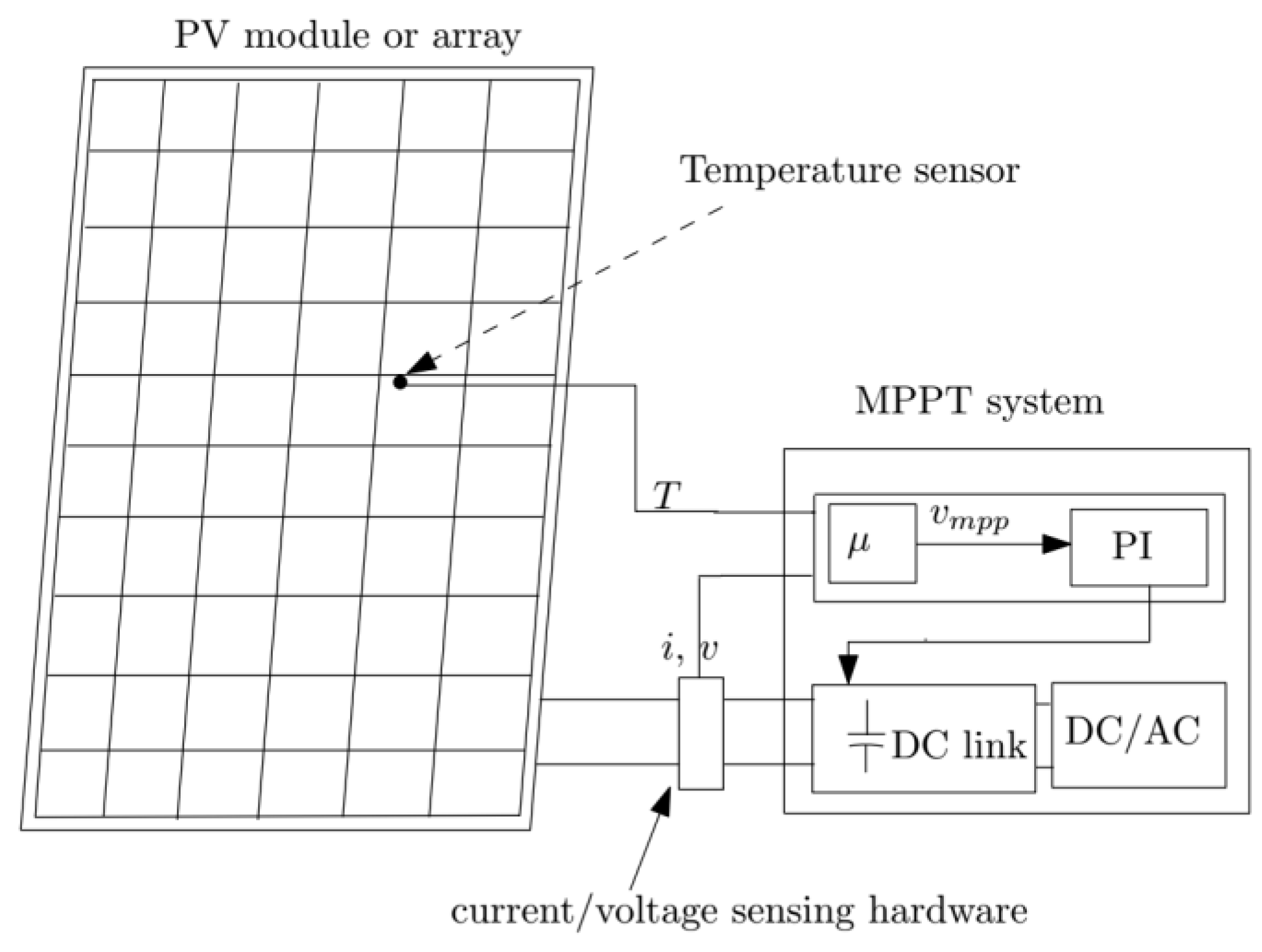
- Maximum Power Point Tracking.
- Power plant efficiency monitoring.
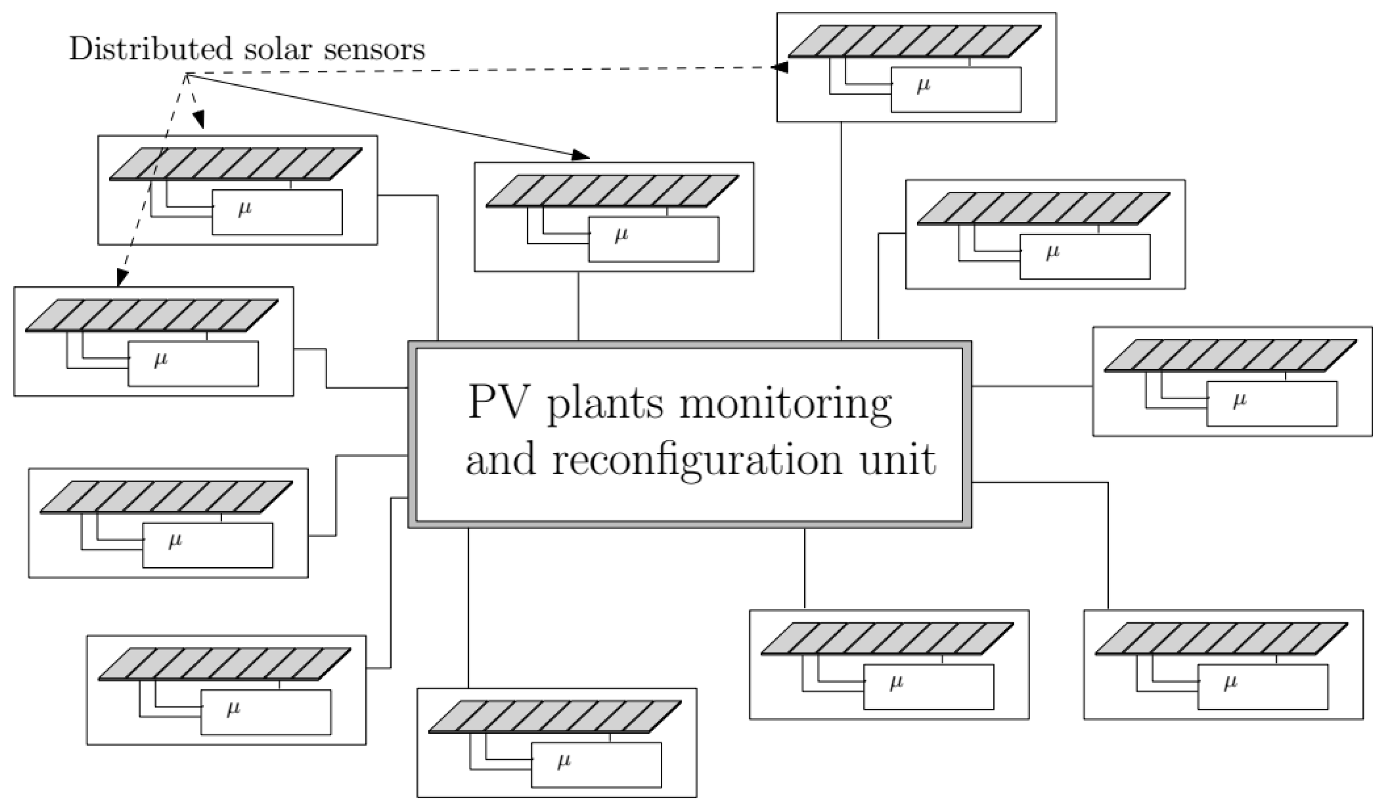
- Reconfiguration of distributed PV plants to manage partial shading problems.
- Monitoring and maintenance for panels’ degradation over time.
- Energy market arbitrage.
- Prediction of power flows for smart grid configuration.
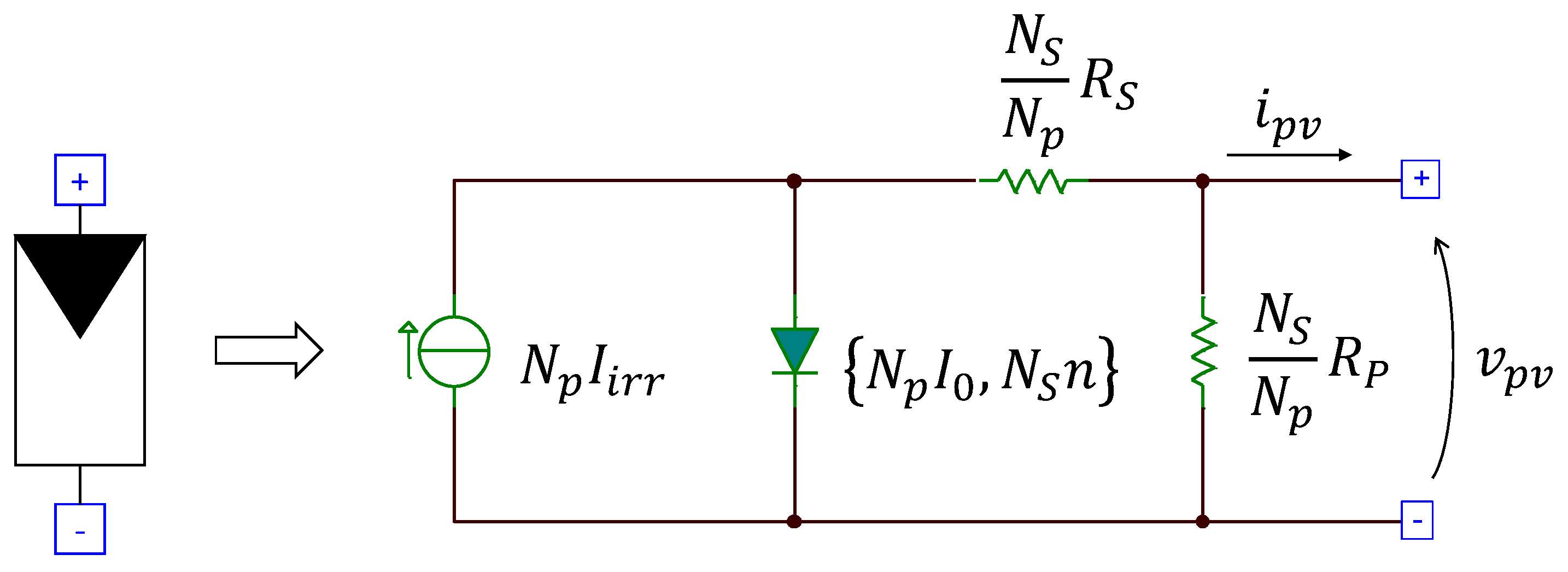
3. The “One Diode” Model and Its Generalization for a PV Array
4. Closed-Form Expression for Solar Irradiance
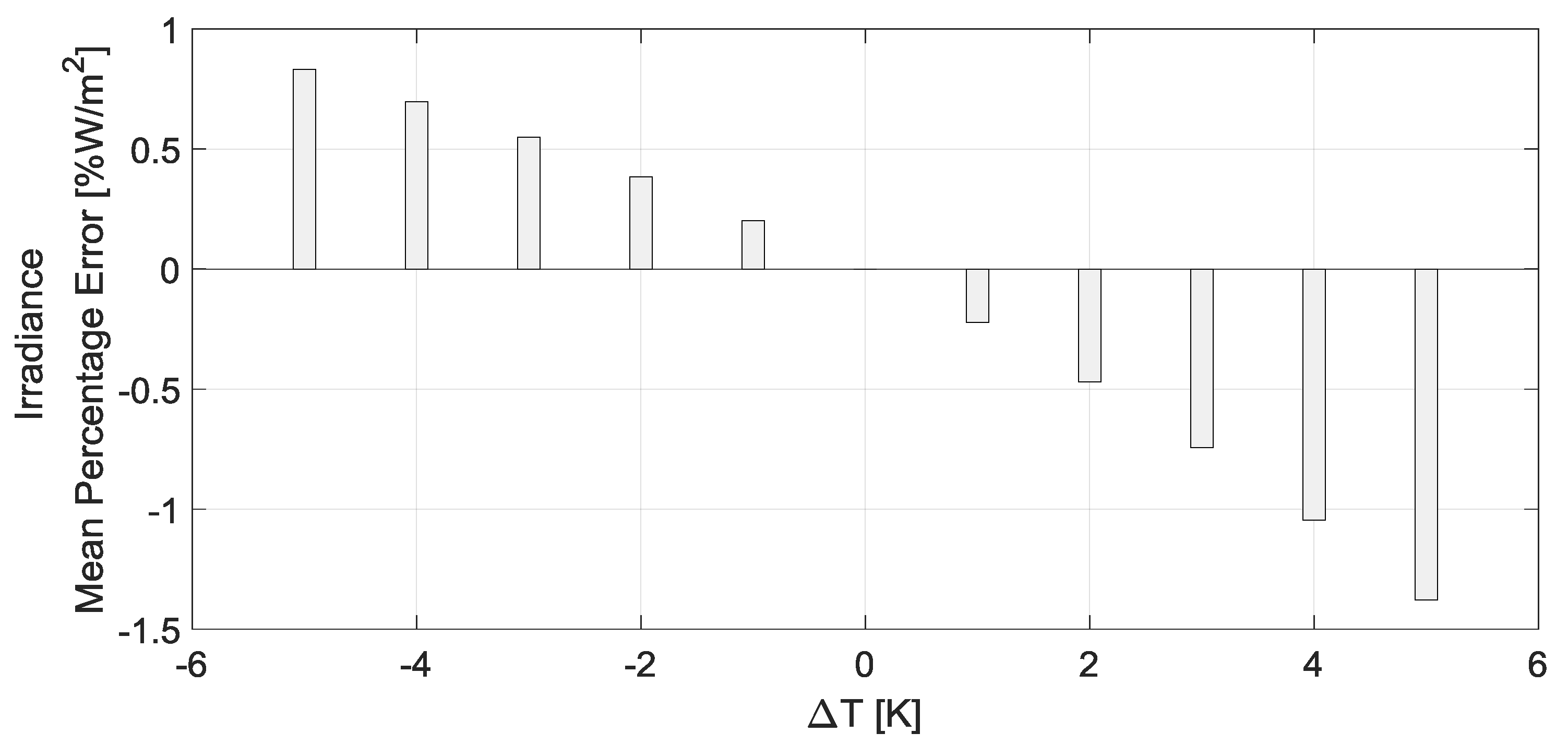
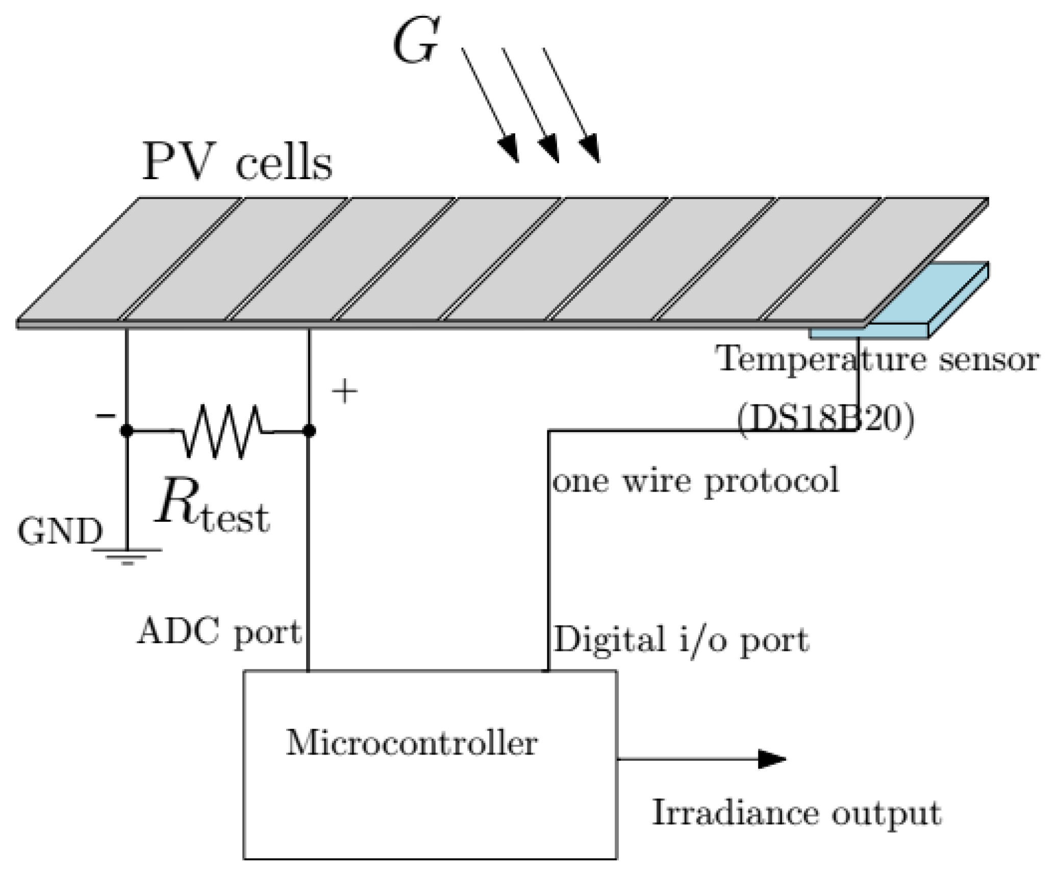
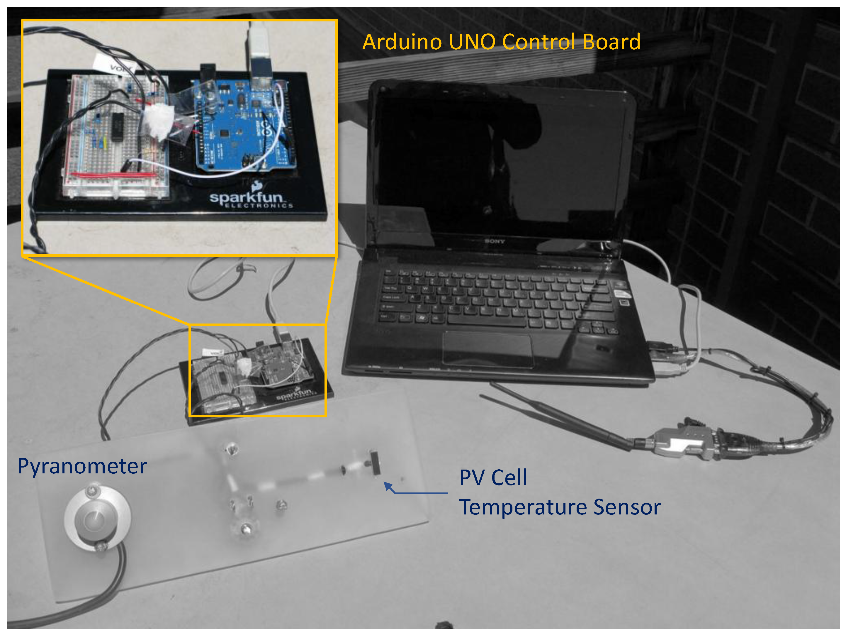
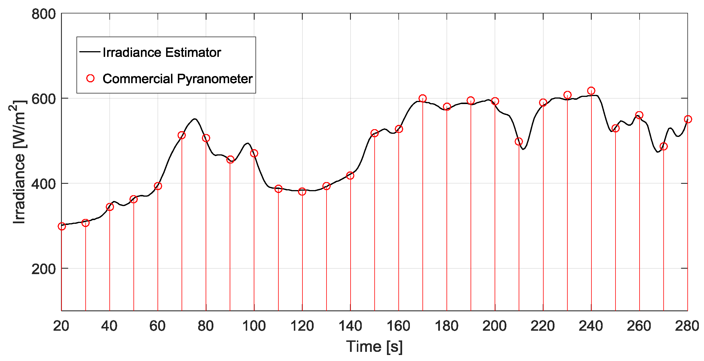
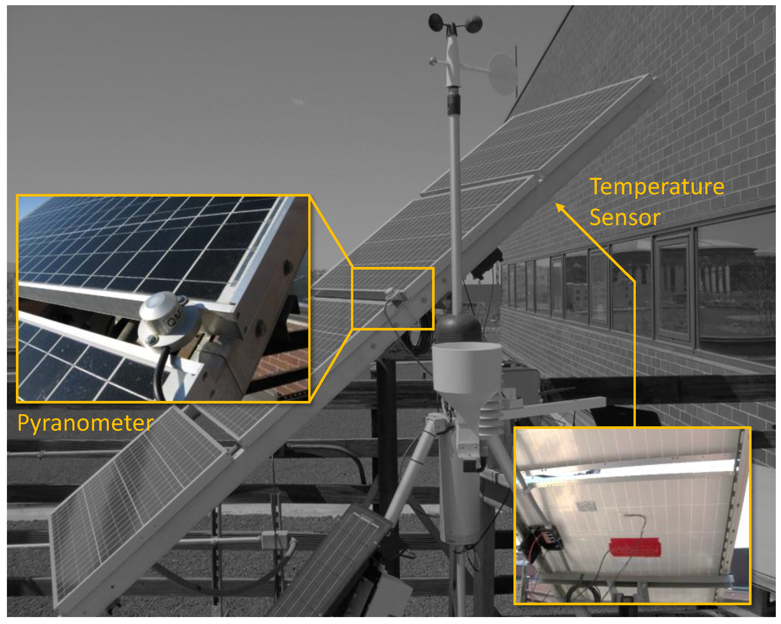
5. Experimental Setup and Validation
5.1. Low Power PV Array
5.2. Medium-Power PV Device
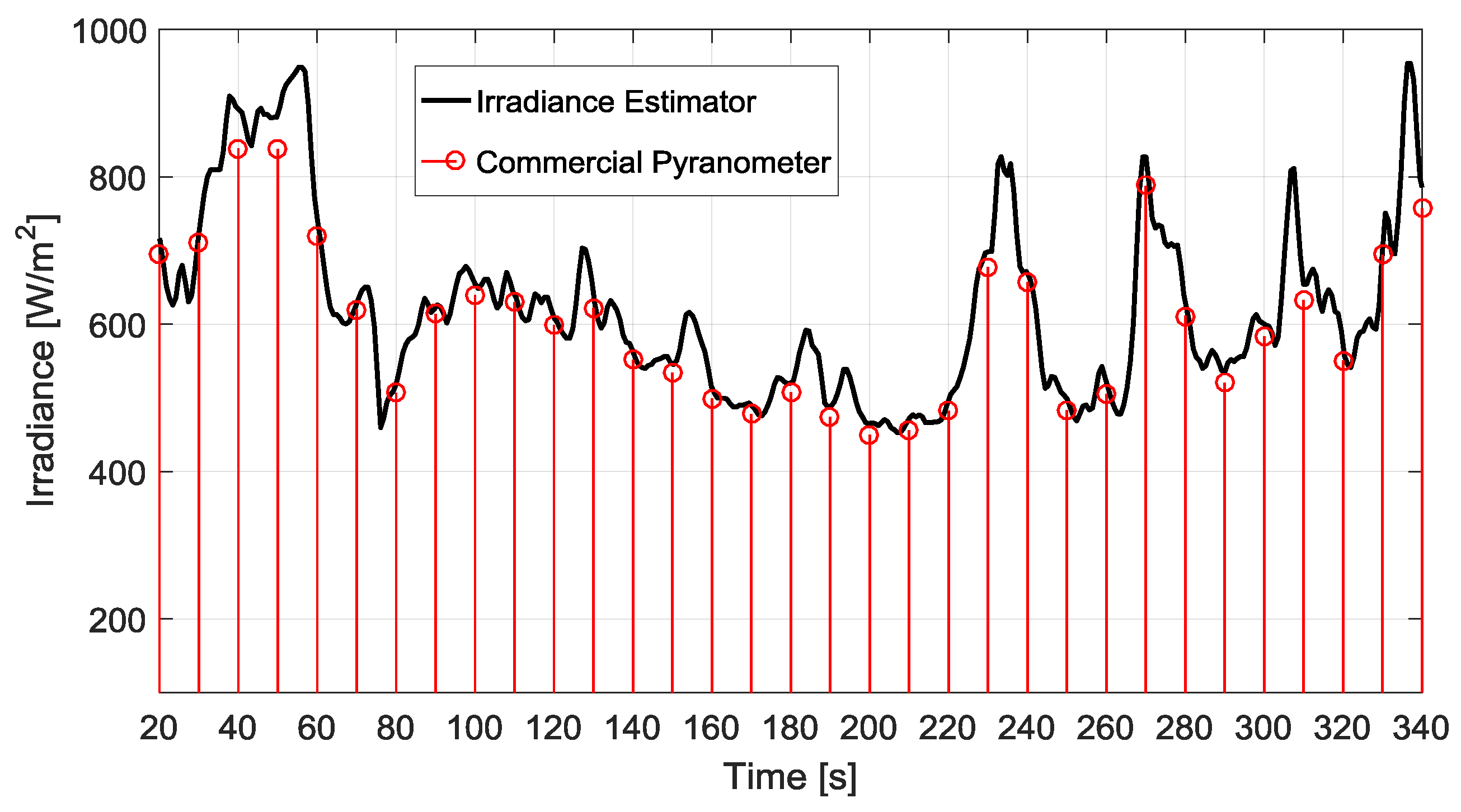
5.3. Neural Network-Based Pyranometer Comparison
6. Applications
7. Conclusions
Author Contributions
Conflicts of Interest
References
- Lave, M.; Reno, M.J.; Stein, J.; Smith, R. Low-cost solar variability sensors for ubiquitous deployment. In Proceedings of the IEEE 42nd Photovoltaic Specialist Conference (PVSC), New Orleans, LA, USA, 14–19 June 2015; pp. 1–6. [Google Scholar]
- Velasco-Quesada, G.; Guinjoan-Gispert, F.; Pique-Lopez, R.; Roman-Lumbreras, M.; Conesa-Roca, A. Electrical PV array reconfiguration strategy for energy extraction improvement in grid-connected PV systems. IEEE Trans. Ind. Electr. 2009, 56, 4319–4331. [Google Scholar] [CrossRef]
- Cristaldi, L.; Faifer, M.; Rossi, M.; Ponci, F. A simple photovoltaic panel model: Characterization procedure and evaluation of the role of environmental measurements. IEEE Trans. Instrum. Meas. 2012, 61, 2632–2641. [Google Scholar] [CrossRef]
- Husain, N.; Zainal, N.; Singh, B.; Mohamed, N.; Mohd, N.N. Integrated PV based solar insolation measurement and performance monitoring system. In Proceedings of the 2011 IEEE Colloquium on Humanities, Science and Engineering (CHUSER), Penang, Malaysia, 5–6 December 2011; pp. 710–715. [Google Scholar]
- Cruz-Colon, J.; Martinez-Mitjans, L.; Ortiz-Rivera, E. Design of a low cost irradiance meter using a photovoltaic panel. In Proceedings of the 2012 38th IEEE Photovoltaic Specialists Conference (PVSC), Austin, TX, USA, 3–8 June 2012; pp. 002911–002912. [Google Scholar]
- Tan, R.; Tai, P.; Mok, V. Solar irradiance estimation based on photovoltaic module short circuit current measurement. In Proceedings of the 2013 IEEE International Conference on Smart Instrumentation, Measurement and Applications (ICSIMA), Kuala Lumpur, Malaysia, 25–27 November 2013; pp. 1–4. [Google Scholar]
- Dunn, L.; Gostein, M.; Emery, K. Comparison of Pyranometers vs. PV reference cells for evaluation of PV array performance. In Proceedings of the 2012 38th IEEE Photovoltaic Specialists Conference (PVSC), Austin, TX, USA, 3–8 June 2012; pp. 002899–002904. [Google Scholar]
- Mancilla-David, F.; Riganti Fulginei, F.; Laudani, A.; Salvini, A. A neural network-based low-cost solar irradiance sensor. IEEE Trans. Instrum. Meas. 2014, 63, 583–591. [Google Scholar] [CrossRef]
- Laudani, A.; Riganti Fulginei, F.; Salvini, A.; Lozito, G.M.; Mancilla-David, F. Implementation of a neural MPPT algorithm on a low-cost 8-bit microcontroller. In Proceedings of the International Symposium on Power Electronics, Electrical Drives, Automation and Motion (SPEEDAM), Ischia, Italy, 8–20 June 2014; pp. 977–981. [Google Scholar]
- Lozito, G.M.; Bozzoli, L.; Salvini, A. Microcontroller based maximum power point tracking through FCC and MLP neural networks. In Proceedings of the 2014 6th European Embedded Design in Education and Research Conference (EDERC), Milano, Italy, 11–12 September 2014; pp. 207–211. [Google Scholar]
- Lozito, G.M.; Laudani, A.; Riganti Fulginei, F.; Salvini, A. FPGA implementations of feed forward neural network by using floating point hardware accelerators. Adv. Electr. Electr. Eng. 2014, 12, 30. [Google Scholar] [CrossRef]
- Tian, H.; Mancilla-David, F.; Ellis, K.; Muljadi, E.; Jenkins, P. A cell-to-module-to-array detailed model for photovoltaic panels. Sol. Energy 2012, 86, 2695–2706. [Google Scholar] [CrossRef]
- Soto, W.D.; Klein, S.; Beckman, W. Improvement and validation of a model for photovoltaic array performance. Sol. Energy 2006, 80, 78–88. [Google Scholar] [CrossRef]
- Varshni, Y.P. Temperature dependence of the energy gap in semiconductors. Physica 1967, 34, 149–154. [Google Scholar] [CrossRef]
- Palankovski, V. 3.3.1 Bandgap Energy. In Simulation of Heterojunction Bipolar Transistors; Institute for Microelectronics: Vienna, Austria, 2000; pp. 227–230. Available online: http://www.iue.tuwien.ac.at/phd/palankovski/node37.html (accessed on 01 March 2017).
- Laudani, A.; Riganti fulginei, F.; Salvini, A. High performing extraction procedure for the one-diode model of a photovoltaic panel from experimental I–V curves by using reduced forms. Sol. Energy 2014, 103, 316–326. [Google Scholar] [CrossRef]
- Laudani, A.; Riganti Fulginei, F.; Salvini, A. Identification of the one-diode model for photovoltaic modules from datasheet values. Sol. Energy 2014, 108, 432–446. [Google Scholar] [CrossRef]
- Laudani, A.; Riganti Fulginei, F.; Salvini, A.; Lozito, G.M.; Coco, S. Very fast and accurate procedure for the characterization of photovoltaic panels from datasheet information. Int. J. Photoenergy 2014, 2014, 10. [Google Scholar] [CrossRef] [PubMed]
- Da Costa, W.T.; Fardin, J.F.; De Vilhena, L.; Machado Neto, B.; Simonetti, D.S.L. Estimation of irradiance and temperature using photovoltaic modules. Sol. Energy 2014, 110, 132–138. [Google Scholar] [CrossRef]
- Patnaik, B.; Mohod, J.; Duttagupta, S. Distributed multi-sensor network for real time monitoring of illumination states for a reconfigurable solar photovoltaic array. In Proceedings of the 2012 1st International Symposium on Physics and Technology of Sensors (ISPTS), Pune, India, 7–10 March 2012; pp. 106–109. [Google Scholar]
- Rivera, E.; Peng, F. Algorithms to estimate the temperature and effective irradiance level over a photovoltaic module using the fixed point theorem. In Proceedings of the 37th IEEE Power Electronics Specialists Conference (PESC ’06), Jeju, Korea, 18–22 June 2006; pp. 1–4. [Google Scholar]


| Parameter | Given by Equation (7) | Given by Equation (8) |
|---|---|---|
| [mA] | 4.55047 | 4.55113 |
| [fA] | 7.66111 × 10⁻⁷ | 5.59818 × 10⁻⁷ |
| 249.28221 | 249.76964 | |
| 7.28921 | 7.27189 | |
| 0.53078 | 0.52695 |
| Profiling Figure | Neural Network | Closed Form |
|---|---|---|
| latency (clock cycles) | ≈58,000 | ≈15,650 |
| occupied Bytes | ≈450 | ≈350 |
| All. Bytes Static Random Access Memory (SRAM) (%) | ≈0.99% | ≈1.03% |
| computations/s | ≈800 | ≈3000 |
© 2017 by the authors. Licensee MDPI, Basel, Switzerland. This article is an open access article distributed under the terms and conditions of the Creative Commons Attribution (CC BY) license (http://creativecommons.org/licenses/by/4.0/).
Share and Cite
Carrasco, M.; Laudani, A.; Lozito, G.M.; Mancilla-David, F.; Riganti Fulginei, F.; Salvini, A. Low-Cost Solar Irradiance Sensing for PV Systems. Energies 2017, 10, 998. https://doi.org/10.3390/en10070998
Carrasco M, Laudani A, Lozito GM, Mancilla-David F, Riganti Fulginei F, Salvini A. Low-Cost Solar Irradiance Sensing for PV Systems. Energies. 2017; 10(7):998. https://doi.org/10.3390/en10070998
Chicago/Turabian StyleCarrasco, Miguel, Antonino Laudani, Gabriele Maria Lozito, Fernando Mancilla-David, Francesco Riganti Fulginei, and Alessandro Salvini. 2017. "Low-Cost Solar Irradiance Sensing for PV Systems" Energies 10, no. 7: 998. https://doi.org/10.3390/en10070998
APA StyleCarrasco, M., Laudani, A., Lozito, G. M., Mancilla-David, F., Riganti Fulginei, F., & Salvini, A. (2017). Low-Cost Solar Irradiance Sensing for PV Systems. Energies, 10(7), 998. https://doi.org/10.3390/en10070998