Control Strategy for a Grid-Connected Inverter under Unbalanced Network Conditions—A Disturbance Observer-Based Decoupled Current Approach

 ,
,  ,
,  , , , and
Abstract
1. Introduction
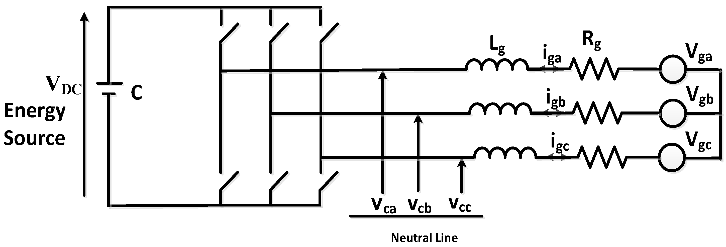
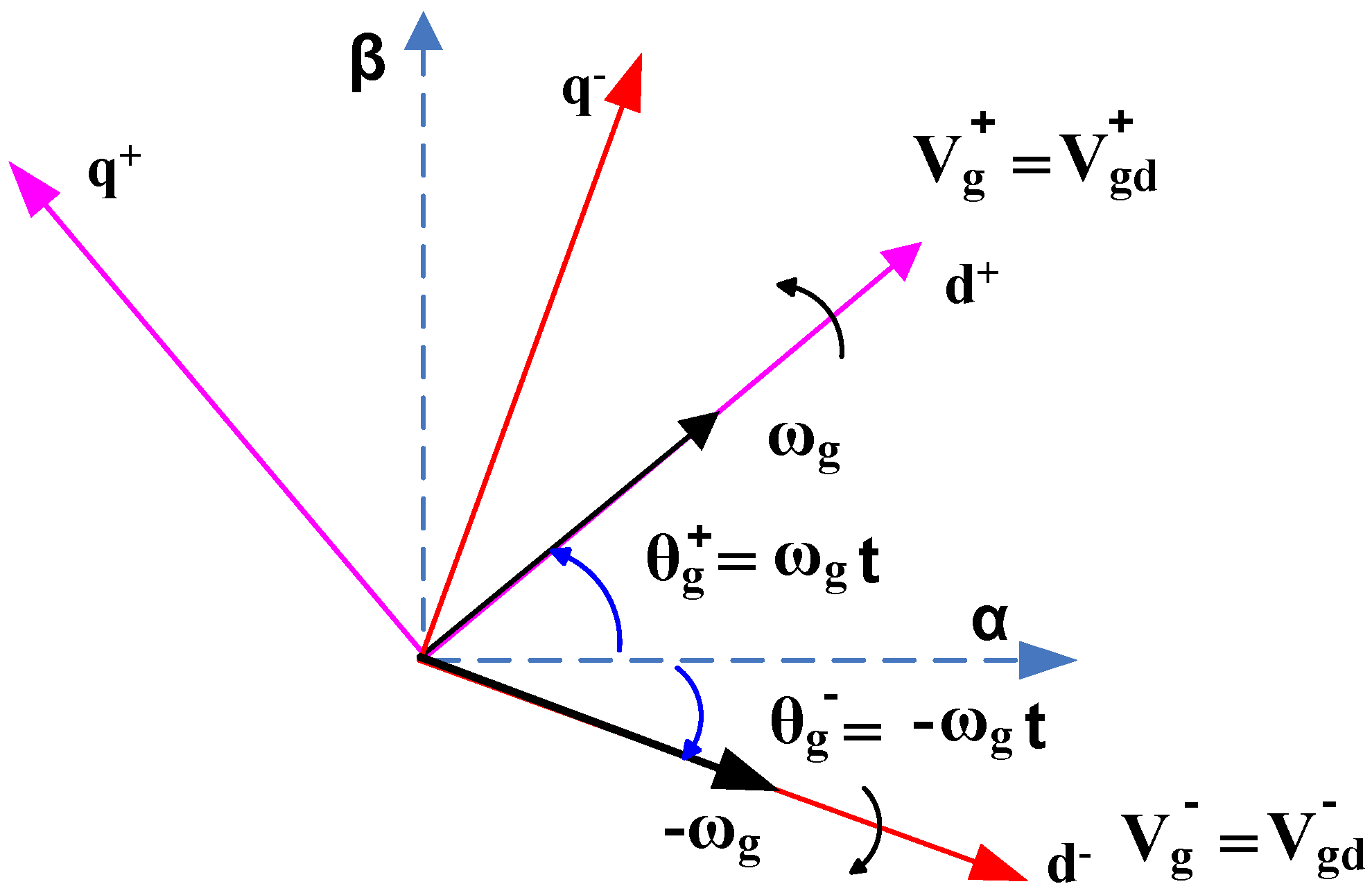
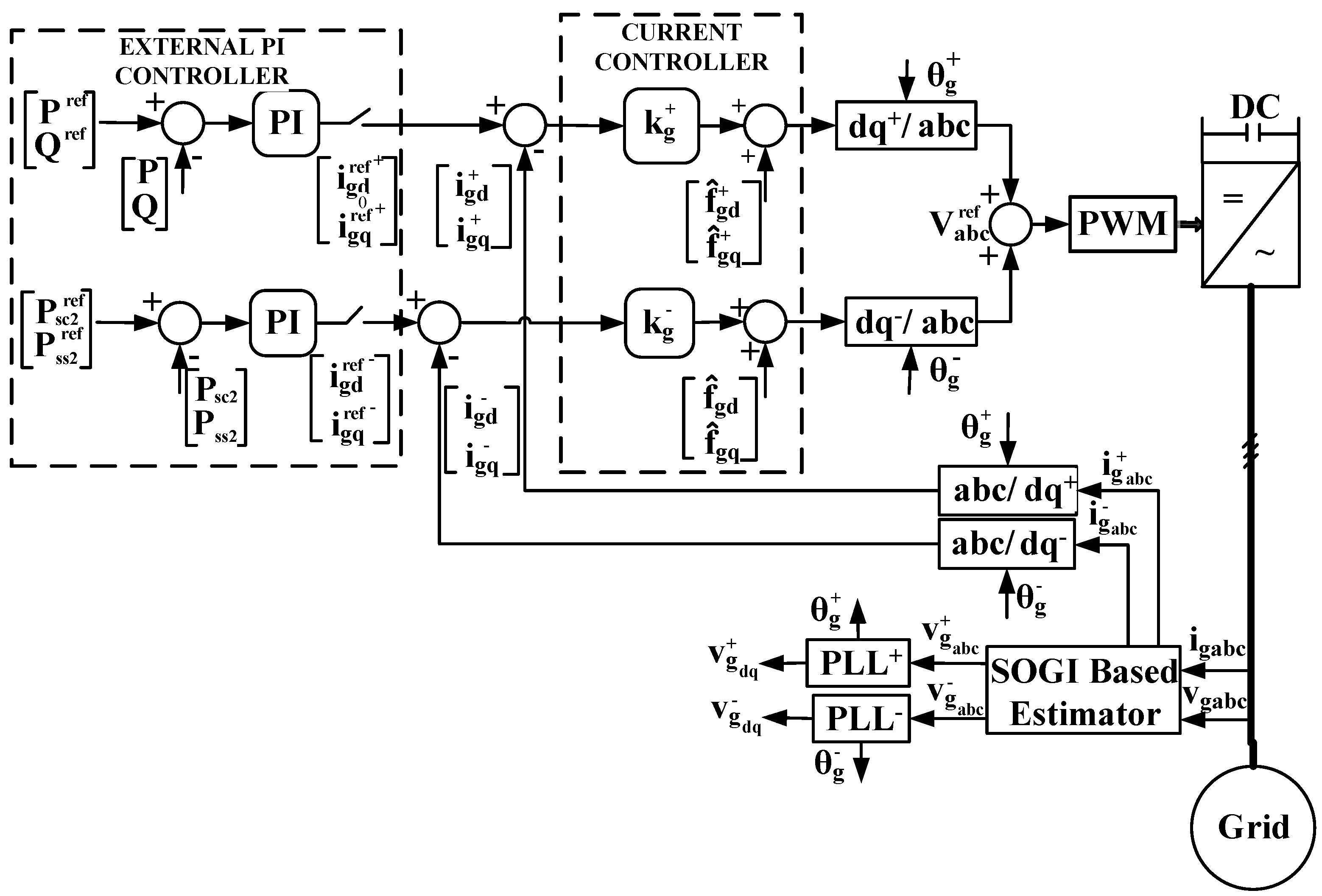
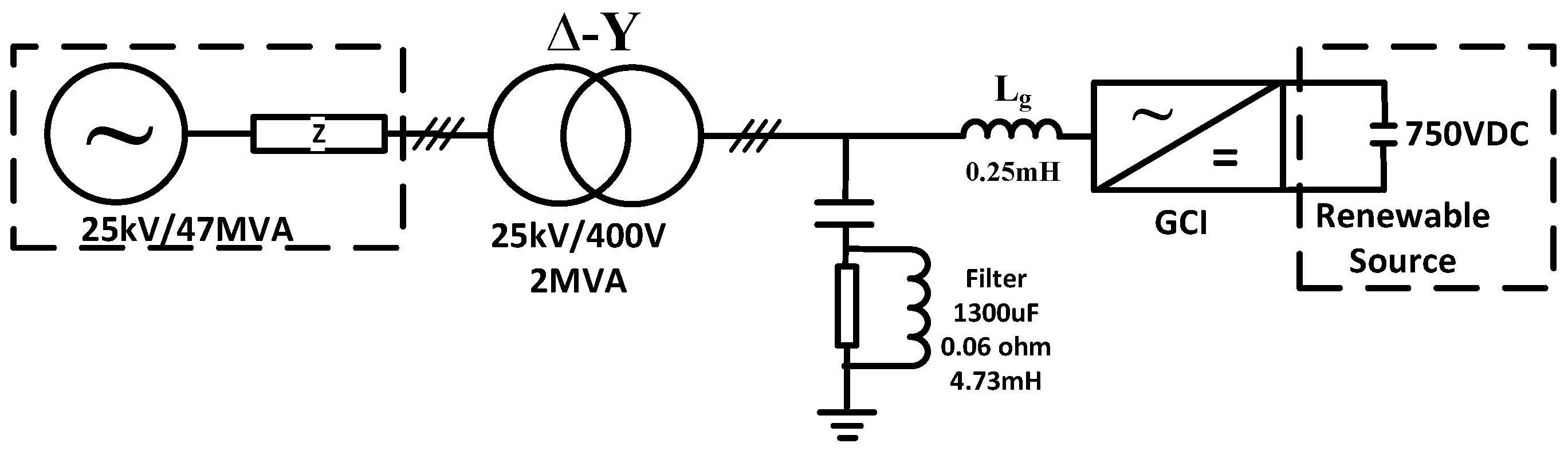
2. Dynamic Model
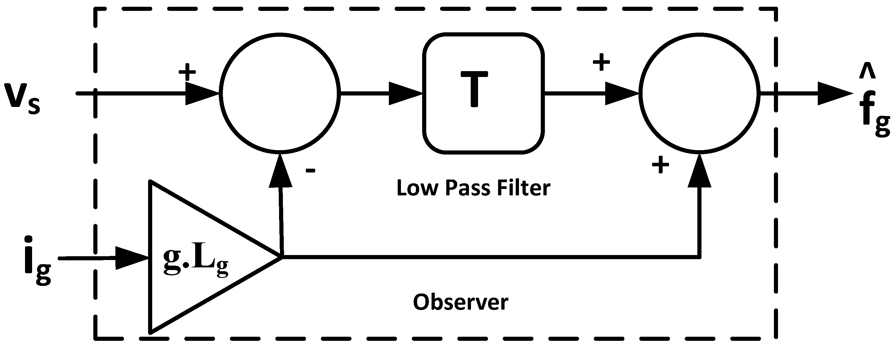
2.1. First-Order Low-Pass Filter Disturbance Observer
2.2. Instantaneous Power Equations
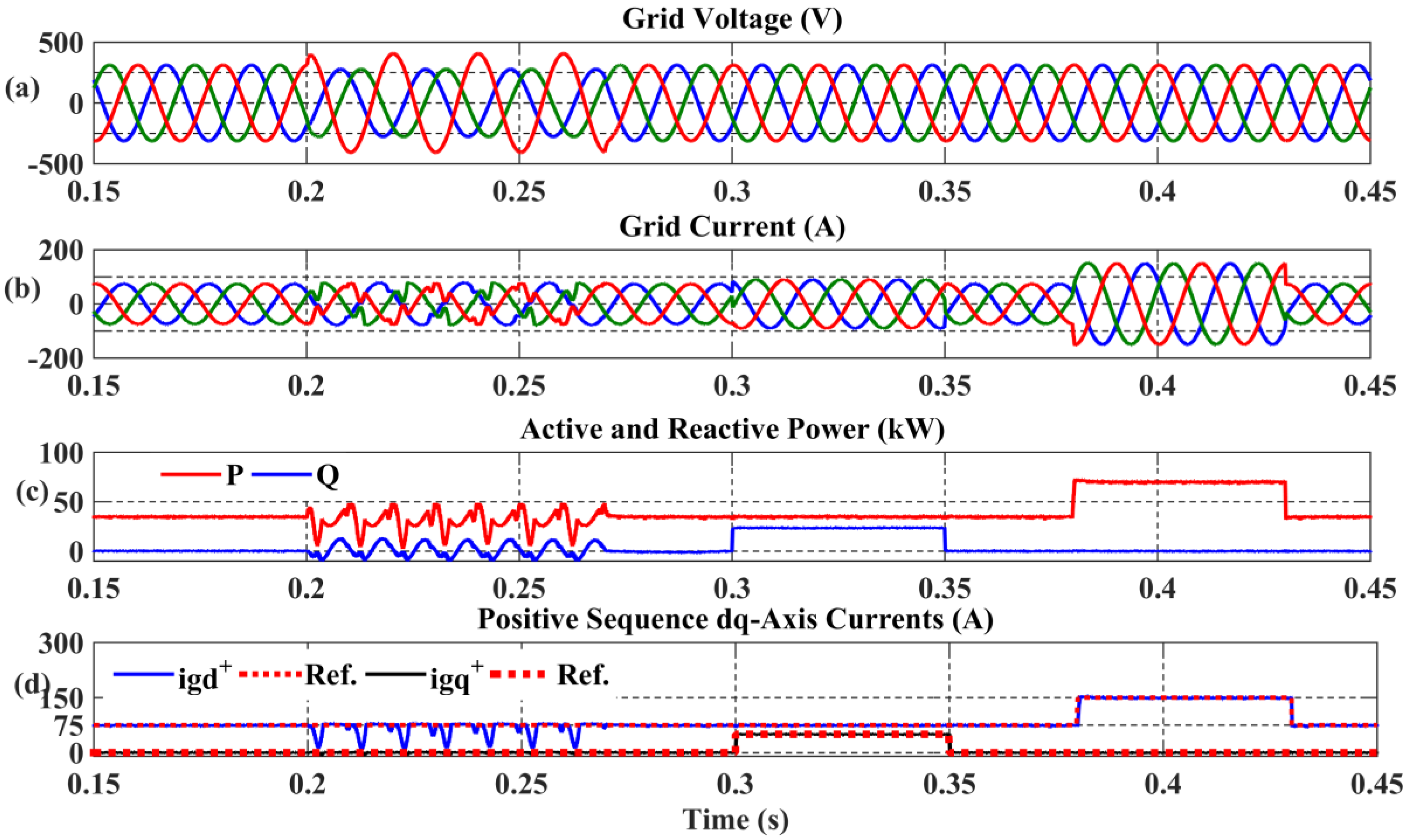
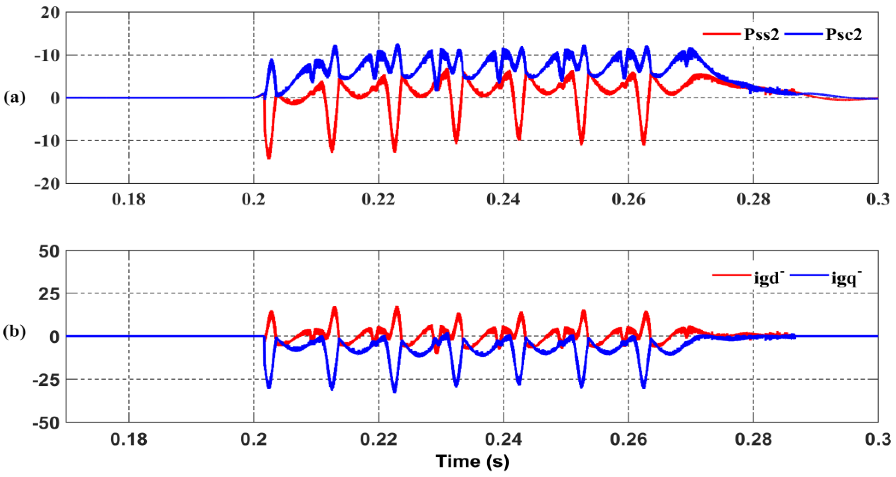
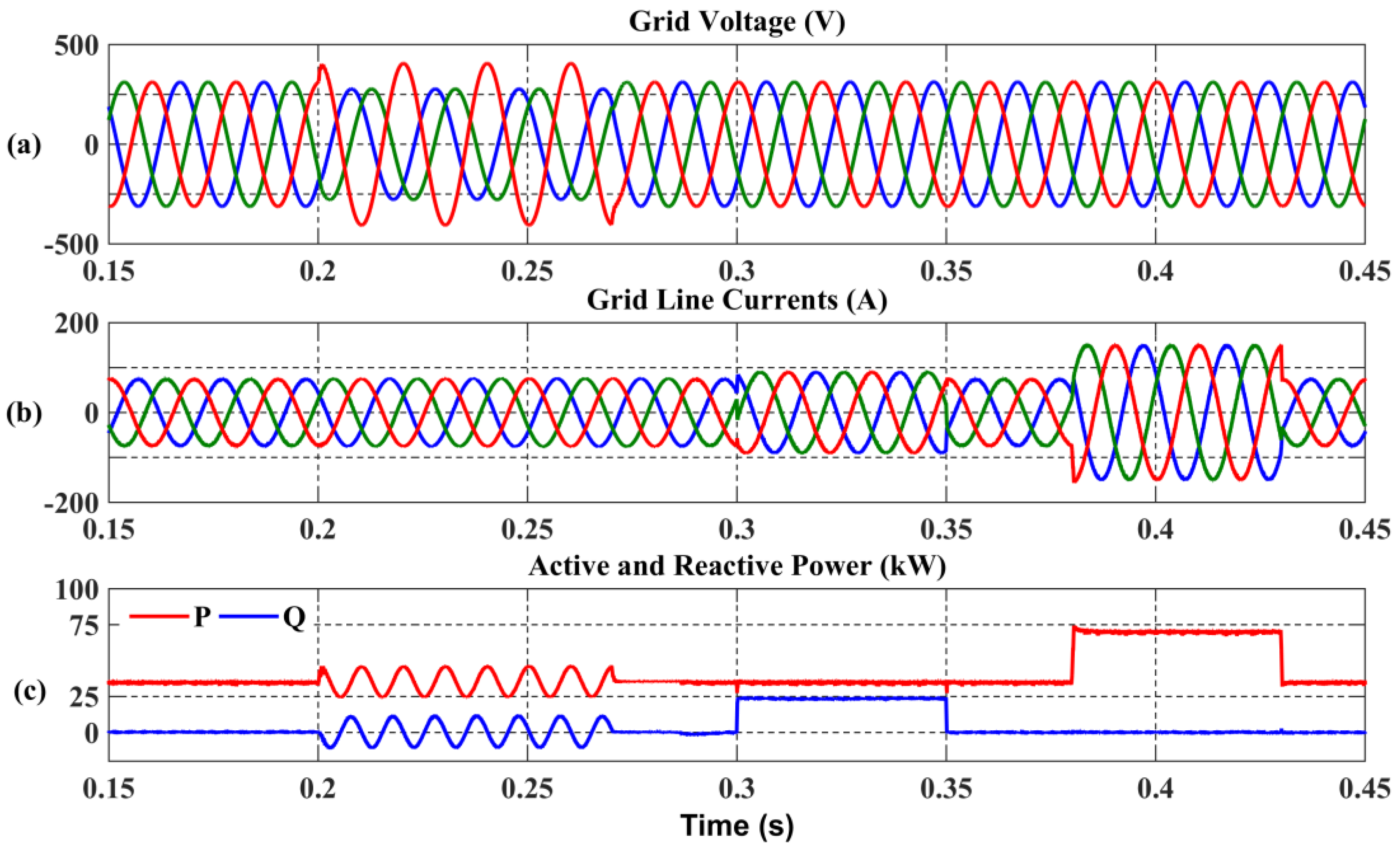
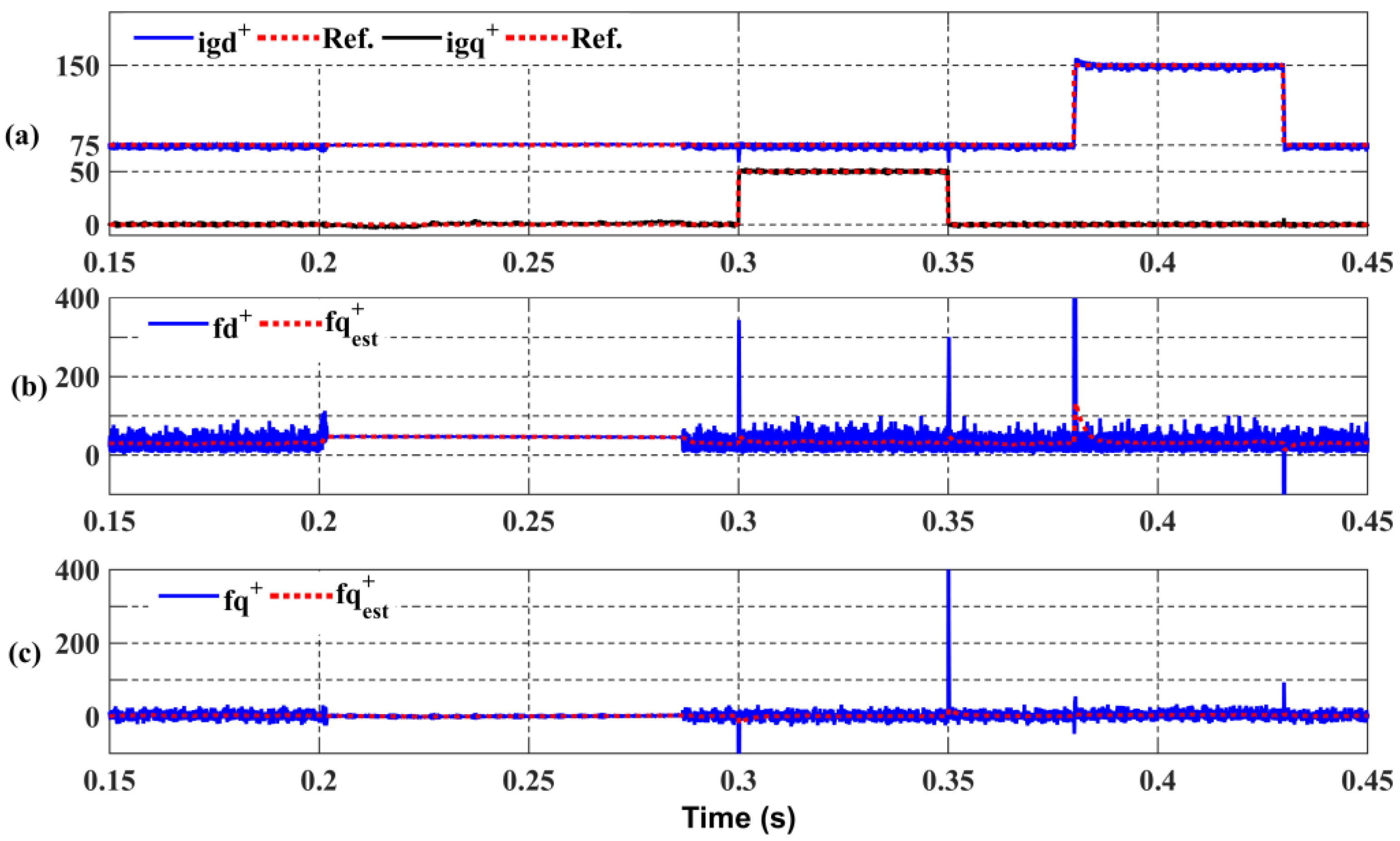
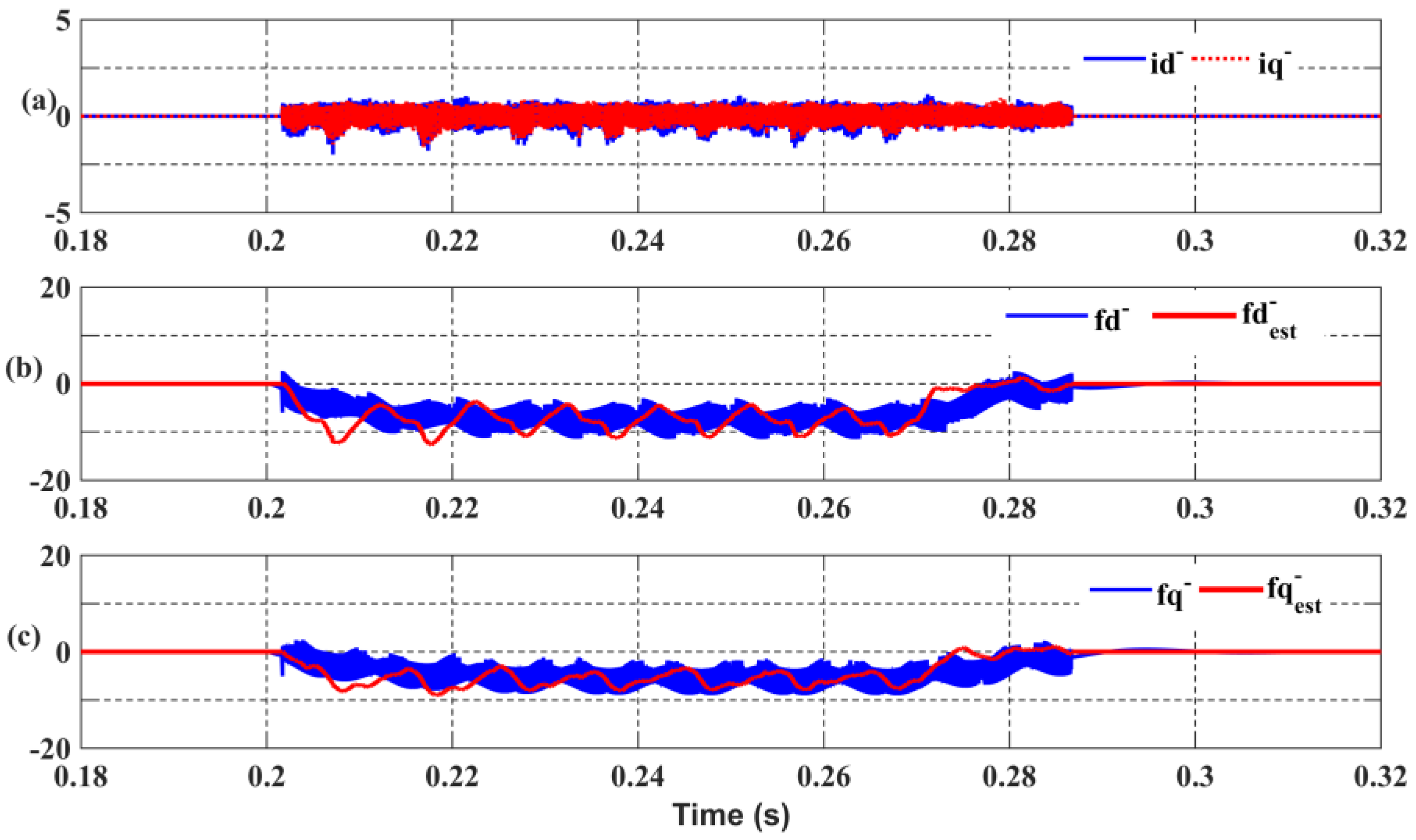
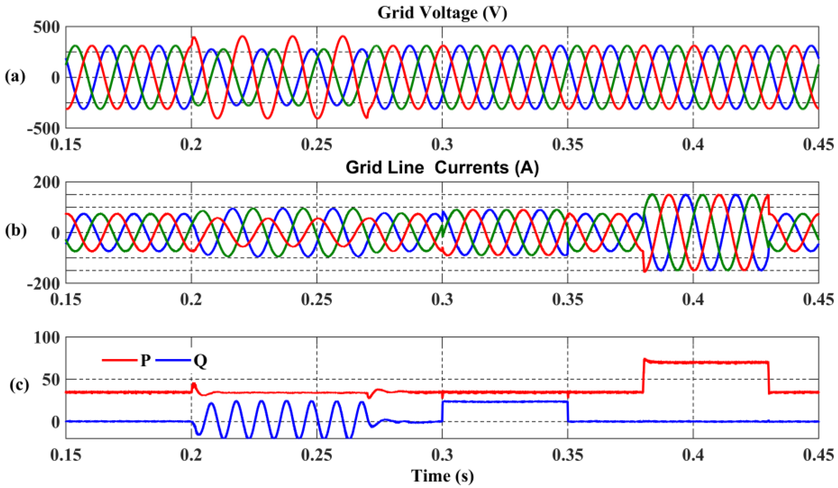
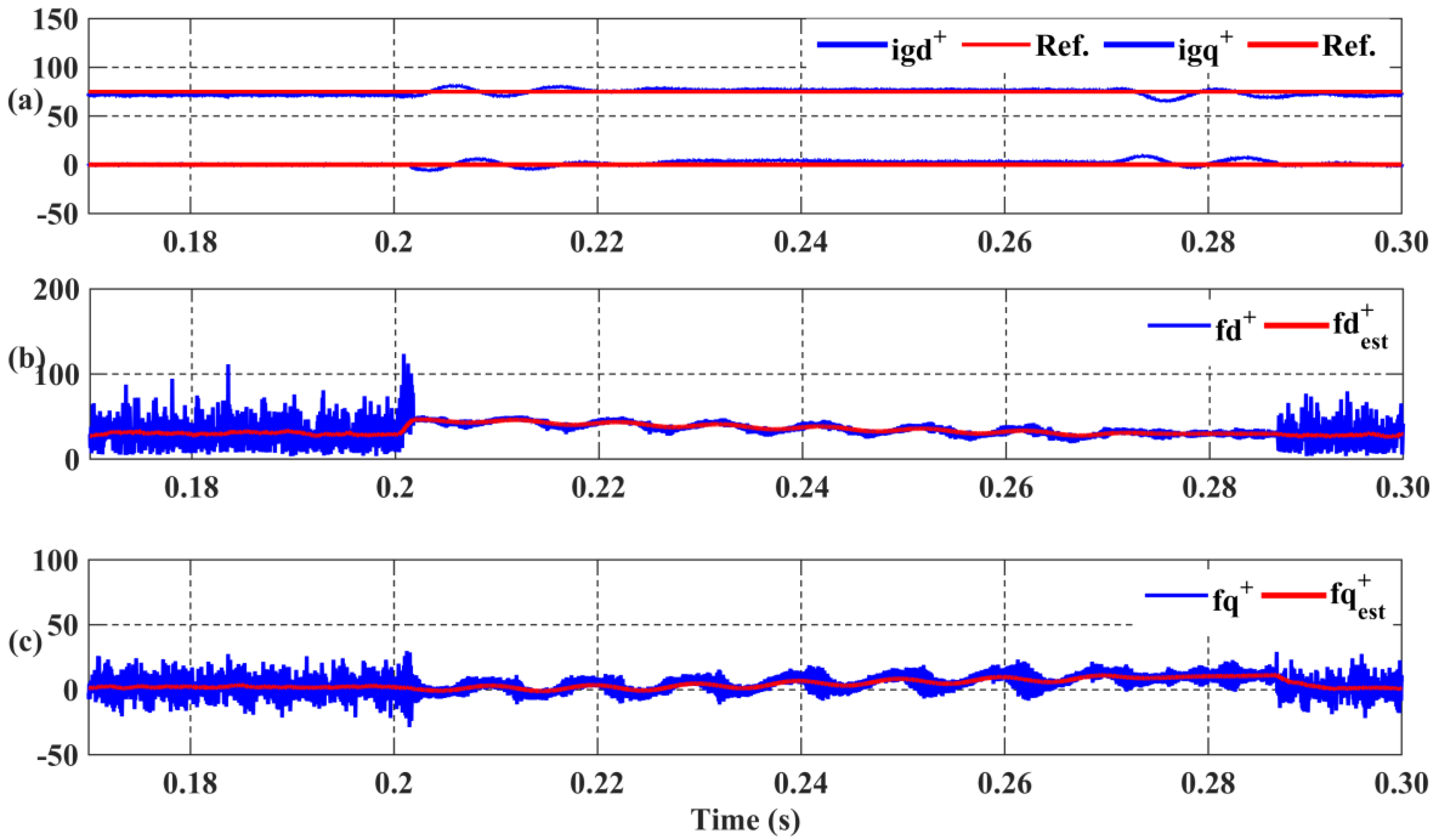
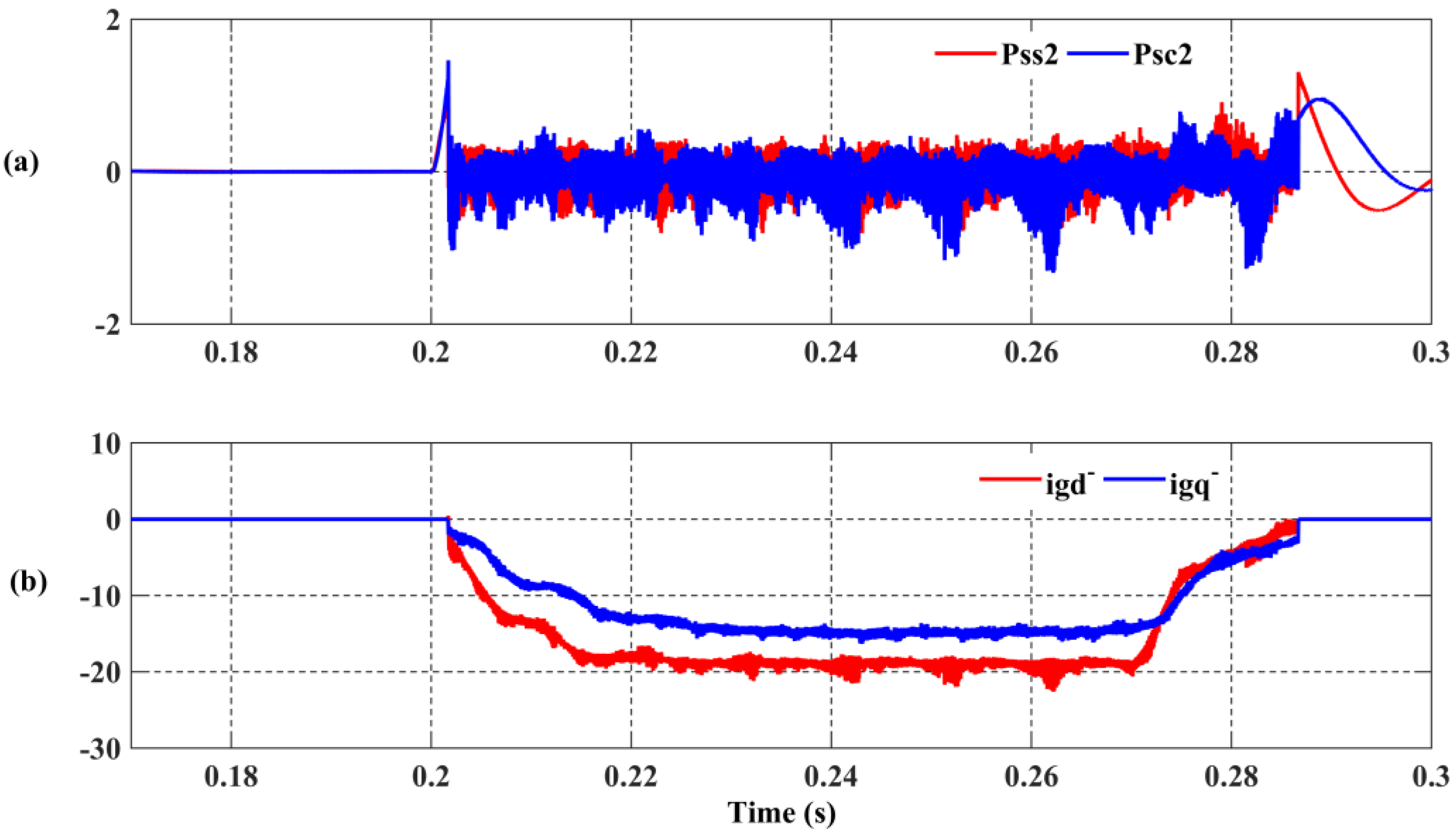
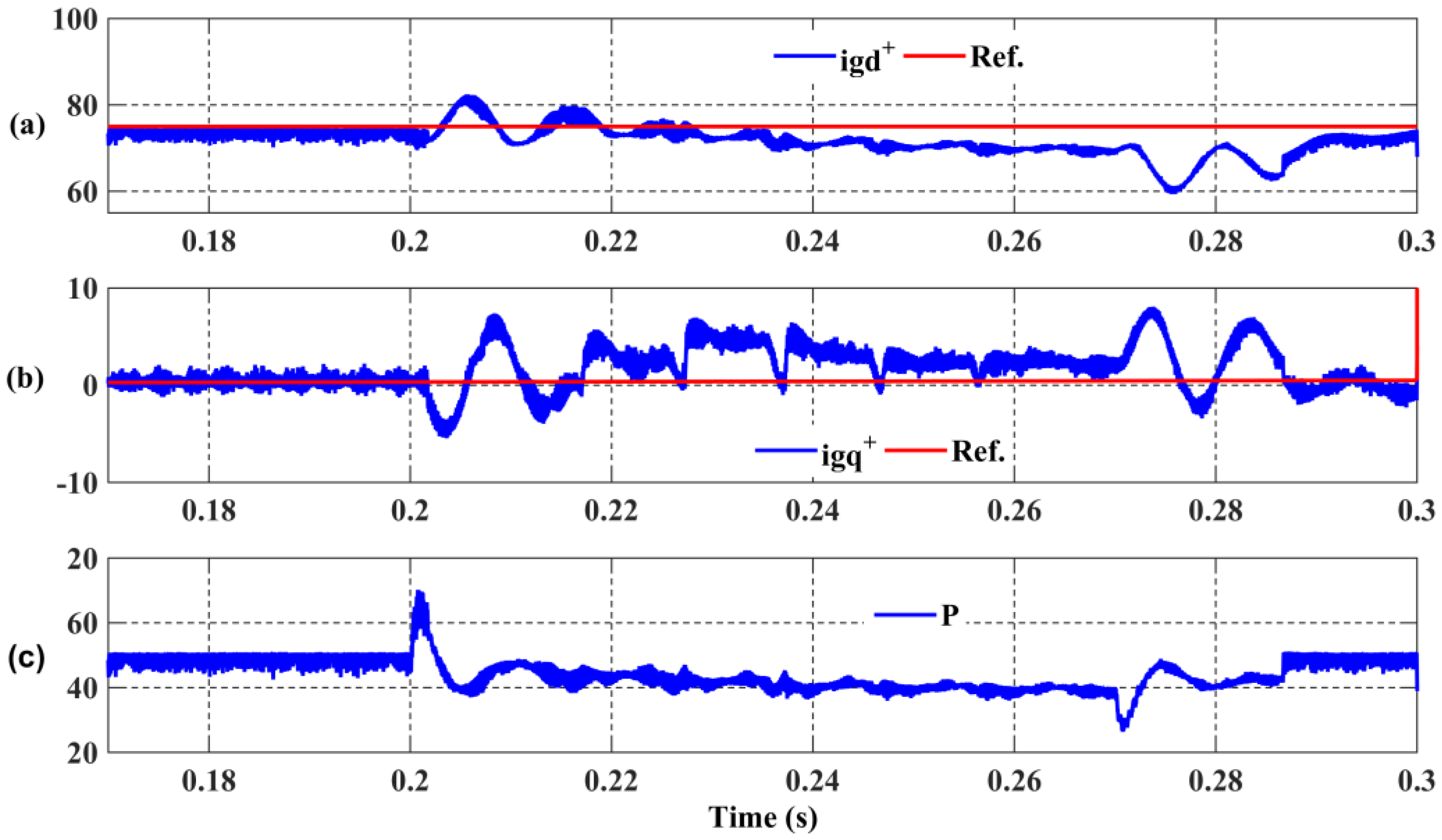
3. Simulation Results
- 0.20–0.27 s: 30% unbalanced voltage condition was generated on phase-A in the grid.
- 0.30–0.35 s: reference step was applied from 75 to 150 A.
- 0.38–0.43 s: reference step was applied from 0 to 50 A.
4. Conclusions
Author Contributions
Conflicts of Interest
References
- Basso, T.S.; DeBlasio, R. IEEE 1547 series of standards: interconnection issues. IEEE Trans. Power Electron. 2004, 19, 1159–1162. [Google Scholar] [CrossRef]
- Markiewicz, H.; Klajn, A. Voltage Disturbances Standard EN50160—Voltage Characteristics in Public Distribution Systems; Copper Development Association: Hertfordshire, UK, 2004. [Google Scholar]
- Sridhar, V.; Umashankar, S.; Sanjeevikumar, P. Decoupled Active and reactive power control of cascaded H-Bridge PV-Inverter for grid connected applications. In Lecture Notes in Electrical Engineering; Springer: Berlin/Heidelberg, Germany, 2017. [Google Scholar]
- Swaminathan, G.; Ramesh, V.; Umashankar, S.; Sanjeevikumar, P. Fuzzy Based micro grid energy management system using interleaved boost converter and three level NPC inverter with improved grid voltage quality. In Lecture Notes in Electrical Engineering; Springer: Berlin/Heidelberg, Germany, 2017. [Google Scholar]
- Swaminathan, G.; Ramesh, V.; Umashankar, S.; Sanjeevikumar, P. Investigations of microgrid stability and optimum power sharing using Robust Control of grid tie PV inverter. In Lecture Notes in Electrical Engineering; Springer: Berlin/Heidelberg, Germany, 2017. [Google Scholar]
- Awasthi, A.; Karthikeyan, V.; Rajasekar, S.; Sanjeevikumar, P.; Siano, P.; Ertas, A. Dual mode control of inverter to integrate solar-wind hybrid fed DC-Grid with distributed AC grid. In Proceedings of the IEEE Conference on Environment and Electrical Engineering, Florence, Italy, 7–10 June 2016. [Google Scholar]
- Mihet-Popa, L. Current Signature Analysis as diagnosis media for incipient fault detection. J. Adv. Electr. Comput. Eng. 2007, 7, 11–16. [Google Scholar] [CrossRef]
- Mihet-Popa, L.; Prostean, O.; Szeidert, I.; Filip, I.; Vasar, C. Fault detection methods for frequency converters fed induction machines. In Proceedings of the 12th IEEE Conference on Emerging Technologies and Factory Automation—ETFA, Patras, Greece, 25–28 September 2007; pp. 161–168. [Google Scholar]
- Das, V.; Sanjeevikumar, P.; Karthikeyan, V.; Rajasekar, S.; Blaabjerg, F.; Pierluigi, S. Recent advances and challenges of fuel cell based power system architectures and control—A review. Renew. Sustain. Energy 2017, 73, 10–18. [Google Scholar] [CrossRef]
- Vavilapalli, S.; Sanjeevikumar, P.; Umashankar, S.; Mihet-Popa, L. Power balancing control for grid energy storage system in PV spplications—Real time digital simulation implementation. Energies 2017, 10, 928. [Google Scholar] [CrossRef]
- Pena, R.; Clare, J.C.; Asher, G.M. A doubly-fed induction generator using two back-to-back PWM converters and its application to variable speed wind energy system. Proc. Inst. Elect. Eng. B 1996, 143, 231–241. [Google Scholar]
- Mihet-Popa, L.; Groza, V.; Prostean, G.; Filip, I.; Szeidert, I. Variable Speed Wind Turbines Using Cage Rotor Induction Generators Connected to the Grid. Proceeding of the IEEE Canada Electrical Power Conference, EPC 2007, Montreal, QC, Canada, 25–26 October 2007. [Google Scholar]
- Mihet-Popa, L.; Groza, V.; Prostean, O.; Szeidert, I. Modeling and design of a grid connection control mode for a small variable-speed wind turbine system. In Proceedings of the IEEE I2MTC-International Instrumentation & Measurement Technology Conference, Vancouver Island, BC, Canada, 12–15 May 2008; pp. 288–293. [Google Scholar]
- Rioual, P.; Pouliquen, H.; Louis, H.P. Control of a PWM rectifier in the unbalanced state by robust voltage regulation. In Proceedings of the 5th European Conference Power Electronics Applications, Brighton, UK, 13–16 September 1993; Volume 4, pp. 8–14. [Google Scholar]
- Song, H.S.; Nam, K. Dual current control scheme for PWM converter under unbalanced input voltage conditions. IEEE Trans. Ind. Electron. 1999, 46, 953–959. [Google Scholar] [CrossRef]
- Suh, Y.; Tijeras, V.; Lipo, T.A. Control scheme in hybrid synchronous stationary frame for PWMAC/DC converter under generalized unbalanced operating conditions. IEEE Trans. Ind. Appl. 2006, 42, 825–835. [Google Scholar]
- Suh, Y.; Tijeras, V.; Lipo, T.A. A control method in dq synchronous frame for PWM boost rectifier under generalized unbalanced operating conditions. In Proceedings of the IEEE 33rd Annual Power Electronics Specialists Conference, Cairns, Australia, 23–27 June 2002; Volume 3, pp. 1425–1430. [Google Scholar]
- Teodorescu, R.; Blaabjerg, F.M.; Liserre, M.; Loh, P.C. Proportional Resonant controllers and filters for grid-connected voltage-source converters. IEE Proc.-Electr. Power Appl. 2006, 153, 750–762. [Google Scholar] [CrossRef]
- Lascu, C.; Asiminoaei, L.; Boldea, I.; Blaabjerg, F. High performance current controller for selective harmonic compensation in active power filters. IEEE Trans. Power Electron. 2007, 22, 1826–1835. [Google Scholar] [CrossRef]
- Serpa, L.A.; Ponnaluri, S.; Barbosa, P.M.; Kolar, J.W. A modified direct power control strategy allowing the connection of three-phase inverters to the grid through LCL filters. IEEE Trans. Ind. Appl. 2007, 43, 1388–1400. [Google Scholar] [CrossRef]
- Vazquez, S.; Sanchez, J.A.; Carrasco, J.M.; Leon, J.I.; Galvan, E. A model-based direct power control for three-phase power converters. IEEE Trans. Ind. Electron. 2008, 55, 1647–1657. [Google Scholar] [CrossRef]
- Reyes, M.; Rodriguez, P.; Vazquez, S.; Luna, A.; Teodorescu, R.; Carrasco, J.M. Enhanced decoupled double synchronous reference frame current controller for unbalanced grid-voltage conditions. IEEE Trans. Power Electron. 2012, 27, 3934–3943. [Google Scholar] [CrossRef]
- Dawei, Z.; Lie, X.; Williams, B.W. Model-based predictive direct power control of doubly fed induction generators. IEEE Trans. Power Electron. 2010, 25, 341–351. [Google Scholar] [CrossRef]
- Cort’es, P.; Rodriguez, J.; Antoniewicz, P.; Kazmierkowski, M. Direct power control of an AFE using predictive control. IEEE Trans. Power Electron. 2008, 23, 2516–2553. [Google Scholar] [CrossRef]
- Rodriguez, C.P.; Timbus, A.V.; Teodorescu, R.; Liserre, M.; Blaabjerg, F. Independent PQ control for distributed power generation systems under grid faults. In Proceedings of the IEEE Industrial Electronics 32nd Annual Conference IECON, Paris, France, 6–10 November 2006; pp. 5185–5190. [Google Scholar]
- Wang, Y.; Beibei, R.; Zhong, Q.C. Robust power flow control of grid-connected inverters. IEEE Trans. Ind. Electron. 2016, 63, 6687–6897. [Google Scholar] [CrossRef]
- Ortjohann, E.; Arturo, A.; Morton, D.; Mohd, A.; Hamsic, N.; Omari, O. Grid-forming three-phase inverters for unbalanced loads in hybrid power systems. In Proceedings of the 2006 IEEE 4th World Conference on Photovoltaic Energy Conference, Waikoloa, HI, USA, 7–12 May 2006. [Google Scholar]
- Vechium, I.; Camblong, H.; Tapia, G.; Curea, O.; Dakyo, B. Modelling and control of four-wire voltage source inverter under unbalanced voltage condition for hybrid power system applications. In Proceedings of the 2005 European Conference on Power Electronics and Applications, Dresden, Germany, 11–14 September 2005. [Google Scholar]
- Chung, S.K. A phase tracking system for three phase utility interface inverters. IEEE Trans. Power Electron. 2000, 15, 431–438. [Google Scholar] [CrossRef]
- Rodriguez, P.; Pou, J.; Bergas, J.; Candela, J.; Burgos, R.P.; Boroyevich, D. Decoupled double synchronous reference frame PLL for power converters control. IEEE Trans. Power Electron. 2007, 22, 584–592. [Google Scholar] [CrossRef]
- Rodriguez, P.; Luna, A.; Teodorescu, R.; Iov, F.; Blaabjerg, F. Fault ride-through capability implementation in wind turbine converters using a decoupled double synchronous reference frame PLL. In Proceedings of the Power Electronics and Applications European Conference, Aalborg, Denmark, 2–5 September 2007; pp. 1–10. [Google Scholar]
- Ciobotaru, M.; Teodorescu, R.; Blaabjerg, F. A new single-phase PLL structure based on second order generalized integrator. In Proceedings of the Power Electronics Specialists Conference, Jeju, Korea, 18–22 June 2006; pp. 1–6. [Google Scholar]
- Iravani, M.R.; Karimi-Ghartemani, M. Online estimation of steady state and instantaneous symmetrical components. IEEE Proc. Gener. Transm. Distrib. 2003, 150, 616–622. [Google Scholar] [CrossRef]
- Ohnishi, K.; Shibata, M.; Murakami, T. Motion control for advanced mechatronics. IEEE/ASME Trans. Mechatron. 1996, 1, 56–67. [Google Scholar] [CrossRef]
- Tamvada, K.; Umashankar, S.; Sanjeevikumar, P. Investigation of double fed induction generator behavior under Symmetrical and Asymmetrical Fault Conditions. In Lecture Notes in Electrical Engineering; Springer: Berlin/Heidelberg, Germany, 2017. [Google Scholar]
- Tamvada, K.; Umashankar, S.; Sanjeevikumar, P. Impact of Power Quality Disturbances on Grid Connected Double Fed Induction Generator. In Lecture Notes in Electrical Engineering; Springer: Berlin/Heidelberg, Germany, 2017. [Google Scholar]
- Tiwaria, R.; Babu, N.R.; Sanjeevikumar, P. A Review on GRID CODES—Reactive power management in power grids for Doubly-Fed Induction Generator in Wind Power application. In Lecture Notes in Electrical Engineering; Springer: Berlin/Heidelberg, Germany, 2017. [Google Scholar]
- Kalaivani, C.; Sanjeevikumar, P.; Rajambal, K.; Bhaskar, M.S.; Mihet-Popa, L. Grid Synchronization of Seven-phase Wind Electric Generator using d-q PLL. Energies 2017, 10, 926. [Google Scholar] [CrossRef]
- Ozsoy, E.E.; Golubovic, E.; Sabanovic, A.; Gokasan, M.; Bogosyan, S. A novel current controller scheme for doubly fed induction generators. Autom. J. Control Meas. Electron Comput. Commun. 2015, 56, 186–195. [Google Scholar] [CrossRef]
- Ozsoy, E.E.; Golubovic, E.; Sabanovic, A.; Gokasan, M.; Bogosyan, S. Modeling and control of a doubly fed induction generator with a disturbance observer: A stator voltage oriented approach. Turk. J. Electr. Eng. Comput. Sci. 2016, 24, 961–972. [Google Scholar] [CrossRef]
- Akagi, H.; Watanabe, E.H.; Aredes, M. Instantaneous Power Theory and Applications to Power Conditioning; John Wiley & Sons: New York, NY, USA, 2007. [Google Scholar]
- Krause, P.C.; Wasynczuk, O.; Sudhoff, S.D. Analysis of Electrical Machinery and Drive Systems, 2nd ed.; John Wiley & Sons: New York, NY, USA, 2002. [Google Scholar]
- Sabanovic, A.; Ohnishi, K. Motion Control Systems; John Wiley & Sons: New York, NY, USA, 2011. [Google Scholar]
- Teodorescu, R.; Liserre, M.; Rodriguez, P. Grid Converters for Photovoltaic and Wind Power Systems; John Wiley & Sons: New York, NY, USA, 2011. [Google Scholar]
- Xu, L. Coordinated control of DFIG’s rotor and grid side converters during network unbalance. IEEE Trans. Power Electron. 2008, 23, 1041–1049. [Google Scholar]


| Symbol | Quantity | Unit |
|---|---|---|
| Grid Connnected Inverter (GCI) DC Voltage | 750 | V |
| Nominal GCI Current | 500 | A |
| Nominal GCI Power | 350 | KVA |
| Switching Frequency | 10 | kHz |
| Lg Filter of GCI | 0.25 | mH |
| X/R Ratio of Grid | 7 | - |
| KP (+)/KP (−) | 20 | - |
| gd | 500 | rad |
© 2017 by the authors. Licensee MDPI, Basel, Switzerland. This article is an open access article distributed under the terms and conditions of the Creative Commons Attribution (CC BY) license (http://creativecommons.org/licenses/by/4.0/).
Share and Cite
Ozsoy, E.; Padmanaban, S.; Mihet-Popa, L.; Fedák, V.; Ahmad, F.; Akhtar, R.; Sabanovic, A. Control Strategy for a Grid-Connected Inverter under Unbalanced Network Conditions—A Disturbance Observer-Based Decoupled Current Approach. Energies 2017, 10, 1067. https://doi.org/10.3390/en10071067
Ozsoy E, Padmanaban S, Mihet-Popa L, Fedák V, Ahmad F, Akhtar R, Sabanovic A. Control Strategy for a Grid-Connected Inverter under Unbalanced Network Conditions—A Disturbance Observer-Based Decoupled Current Approach. Energies. 2017; 10(7):1067. https://doi.org/10.3390/en10071067
Chicago/Turabian StyleOzsoy, Emre, Sanjeevikumar Padmanaban, Lucian Mihet-Popa, Viliam Fedák, Fiaz Ahmad, Rasool Akhtar, and Asif Sabanovic. 2017. "Control Strategy for a Grid-Connected Inverter under Unbalanced Network Conditions—A Disturbance Observer-Based Decoupled Current Approach" Energies 10, no. 7: 1067. https://doi.org/10.3390/en10071067
APA StyleOzsoy, E., Padmanaban, S., Mihet-Popa, L., Fedák, V., Ahmad, F., Akhtar, R., & Sabanovic, A. (2017). Control Strategy for a Grid-Connected Inverter under Unbalanced Network Conditions—A Disturbance Observer-Based Decoupled Current Approach. Energies, 10(7), 1067. https://doi.org/10.3390/en10071067