Abstract
The ongoing search for new sources of energy has brought natural gas hydrate (NGH) reservoirs to the forefront of attention in both academia and the industry. The amount of gas reserves trapped within these reservoirs surpasses all of the conventional fossil fuel sources explored so far, which makes it of utmost importance to predict their production potential and safety. One of the challenges facing those attempting to analyse their behaviour is that the large number of involved phases make NGHs unable to ever reach equilibrium in nature. Field-scale experiments are expensive and time consuming. However, computer simulations have now become capable of modelling different gas production scenarios, as well as production optimization analyses. In addition to temperature and pressure, independent thermodynamic parameters for hydrate stabilization include the hydrate composition and concentrations for all co-existing phases. It is therefore necessary to develop and implement realistic kinetic models accounting for all significant routes for dissociation and reformation. The reactive transport simulator makes it easy to deploy nonequilibrium thermodynamics for the study of CH4 production from hydrate-bearing sediments by considering each hydrate-related transition as a separate pseudo reaction. In this work, we have used the expanded version of the RetrasoCodeBright (RCB) reactive transport simulator to model exploitation of the methane hydrate (MH) reservoir located in the Nankai Trough, Japan. Our results showed that higher permeabilities in the horizontal direction dominated the pressure drop propagation throughout the hydrate layers and affected their hydrate dissociation rates. Additionally, the comparison of the vertical well versus the horizontal well pattern indicated that hydrate dissociation was slightly higher in the vertical well scenario compared to the horizontal.
1. Introduction
Clathrate hydrates of gases consist of cages built by hydrogen-bonded water molecules with gas molecules trapped inside them. Gas hydrates are formed under special conditions of pressure and temperature [1]. These conditions can be found in marine shelf sediments [2] and beneath the permafrost of on-shore polar regions. Macroscopically, hydrates appear similar to ice, and are similar to ice where certain properties are concerned. However, if the pressure is high enough, hydrates can remain stable at temperatures above the ice melting point.
Hydrates in nature will be affected by their contact with surrounding gases and liquids, and will, for example, dissociate towards aqueous phases, under-saturated with respect to hydrate formers. Hydrates of on-shore polar regions will also interact with mineral surfaces. Thus, natural gas hydrates (NGHs) are thermodynamically unstable. The worldwide energy requirements are still on the rise, which fuels the drive to explore new energy sources. NGHs as an energy source have recently become a focus of intense interest for both the scientific community and the industry. Even in a conservative estimation, the worldwide amount of energy trapped within NGHs exceeds the total amount of known fossil fuel reserves by a factor of 2. CH4 is the dominant hydrocarbon component of NGHs [3]. However, despite the economic promise, there still remain questions pertaining to the practical exploitation feasibility of these NGH reserves and their long-term safety in view of potentially rising global temperatures that threaten the existence of permafrost regions. Natural geological processes may cause new fractures bringing water under-saturated with CH4 into contact with hydrate deposits, thus resulting in dissociation and new CH4 leakages. There exists a need to improve our understanding of how the worldwide hydrate deposits may respond to the global climate changes, with regards to both local and global consequences. CH4 is in the order of 25 times more aggressive as a greenhouse gas than CO2, so any increase in CH4 emissions into the atmosphere is an environmental concern [4]. Numerical modelling offers a valid option for evaluating the possible future scenarios. When it comes to assessing the energy potential of hydrate reserves, numerical simulations can never be a stand-alone effort. However, one should keep in mind the intrinsic limitations of experimental results due to real hydrate deposits always residing in a stationary situation rather than true equilibrium, due to their non-equilibrium state. This stationary state will be determined by the local flows that develop and evolve over the geological time scale in response to fractures and faults, geochemistry, and a number of other details. These features will be unique for every hydrate deposit and are impossible to reproduce in an experiment lasting just a few months or a few days. Experiments can, however, be used to explore some characteristic properties, although they will never be a tool able to reproduce the real reservoir behaviour alone.
Obtaining an overall picture that takes into account the overall reservoir characteristics, the flow and transport properties and the thermodynamics will provide a valuable insight into possible production methods, and allow one to draw preliminary conclusions. Moreover, performing sensitivity analyses of various characteristic reservoir properties using numeric tools is quite inexpensive compared to conducting real experiments. Some methods proposed for the production of CH4 from hydrate reservoirs include thermal stimulation, depressurization, inhibitor injection [5], and CO2 or mixed CO2/N2 injection leading to an exchange of CH4 [6,7,8,9,10,11]. Except for the exchange technique, the production of gas via these methods will be accompanied by dissociation of the hydrate and a restructuring of unconsolidated sediments during the release of water and gas. The hydrate dissociation results in roughly a 10% reduction in volume. In addition, varying volumes of water will be produced together with the gas. These changes in the pore filling may potentially affect the geo-mechanical stability of the producing area and cause landslides and subsidence [12].
Understanding the long-term processes that take place during and after gas production from NGHs is very important. Field-scale experiments can be prohibitively expensive and time consuming. Despite their limitations, computer simulations can be be a very useful tool when it comes to the analysis of possible long-term effects. They also offer a very inexpensive way to investigate different scenarios and methods of gas production from hydrates [13,14]. The current approach used by most reservoir simulators is to treat the hydrate systems in terms of the hydrate stability curve, i.e., hydrates are considered either as stable if their pressure and temperature fall inside the curve, or as instantly dissociating otherwise. Although some simulators also contain oversimplified kinetics models, they are frequently derived from stirred experiments in a pressure, volume, and temperature laboratory cell. In either case, only temperature and pressure are taken into account, and the only route for the hydrate dissociation is towards gas and liquid water. Neglecting the dependence of phase transitions on concentrations in all the phases is a significant limitation with varying implications over the lifetime of a hydrate-producing reservoir. During the initial pressure reduction stage, it will take time to transport the heat of the dissociation away; in addition, the accompanying change in the fluid flow around the hydrate will have the potential to expose the hydrate to water under-saturated with CH4. On the other hand, the temperature reduction in the reservoir due to gas expansion and the extraction of heat from the surrounding sediment can lead to a reformation of the hydrate. The combined first and second laws of thermodynamics decide the direction of the phase transitions. The most stable hydrates form first, subject to the constraints of mass and heat transport. For a hydrate originally formed from thermogenic hydrocarbon sources, these processes will lead to a variety of hydrate phases differing in composition. Additionally, hydrates formed from different fluid phases will have different compositions. Hydrates can form from CH4 as gasses, but they can also form from CH4 dissolved in water or CH4 trapped in bulk water or water adsorbed alongside the mineral pore wall. A realistic hydrate reservoir simulator needs to handle all the competing phase transitions involving the hydrate. To our best knowledge, RetrasoCodeBright (RCB) is the only hydrate simulator that treats the hydrate phase transitions via a non-equilibrium thermodynamic approach. RCB is a reactive transport hydrate simulator extended to model the CH4 production from NGHs through the depressurization method. Depending on the phases that hydrate formers originate from (CH4 from the gas or aqueous phase), different indices have been assigned to each hydrate-phase transition route. Classical nucleation theory has been utilized to relate the hydrate-phase transition kinetics to non-equilibrium thermodynamics and the associated mass and heat transport. The competing nature of hydrate-phase transitions are handled by means of in-house non-equilibrium thermodynamics package via the minimization of Gibbs free energy changes (details of the code are provided in Appendix A). In this work, we have used the version of RCB described above to simulate CH4 production from a gas hydrate reservoir located in the Nankai Trough, Japan. The model provides a rough picture of the Nankai Trough hydrate reservoir; it is based on available geological data from this field, reviewed in Section 1.1.
1.1. Brief Literature Review of the Nankai Trough Gas Hydrate Field
Many gas hydrate exploration projects have been performed since 1996 by the Japanese Ministry of Economy, Trade and Industry (METI) in the eastern Nankai Trough, located off the Southwest coast of Japan [15]. Two- and three-dimensional seismic surveys have led to the discovery of hydrate-bearing sediments under the Pacific Ocean [16]. Based on the agreement under the Research Consortium for Methane Hydrate Resources in Japan (MH21 project), the eastern Nankai Trough had been assigned as a target for future gas production from hydrate deposits [16]. Thirty wells have been drilled in 16 locations. METI has been conducting many surveys for methane hydrate (MH) exploration purposes [15].
According to results obtained from the “Nankai Trough” wells of 1999 [17] and the METI “Tokai-oki to Kumano-nada” exploratory test wells of 2004 [18,19] by the Ministry of International Trade and Industry (MITI), rich intervals of MHs have been identified in turbidite deposits of the eastern Nankai Trough [15]. The existence of more than 10 concentrated hydrate-bearing layers of sand pore-filling type have been inferred using the well data as well as the 2D/3D seismic survey data [15,20].
The collision between the Izu-Ogasawara and Honshu arcs had a high effect on the tectonic setting of the eastern Nankai Trough [15]. The analysis of the chemical composition and carbon isotopes of core samples from hydrate-bearing deposits has revealed that CH4 is the dominant gas, making up 99% of the total gas amount. Moreover, they were found to have a microbial origins [21]. MH in Nankai has been divided into two categories [22]: (1) MH-concentrated zones (MHCZs), which by definition contain turbidite sandy sediments with a high saturation of hydrates (up to 80%) and have the potential for future production [23]. These zones are located above the bottom simulated reflection (BSR), where a high resistivity is shown in the well log data; they are characterized through strong reflectors by the seismic data [22]. (2) Relatively thin, low-saturation MH layers, where MH is spread within the bearing layer, but is of no interest for production purposes at the present time [22].
Through applying a probabilistic approach, the estimated amount of in-place gas within this area has been reported to be around 1.1 trillion cubic meters (40 TCf), which corresponds to 14 years of gas consumption in Japan [22], of which almost 0.57 trillion cubic meters (20 Tcf) corresponds to methane gas in MHCZs.
Based on the borehole stability and gas productivity, as well as the space available for down-hole equipment installation, several sites were considered as candidates for production tests [23]. The MHCZs were discovered in the β-MHCZ site through coring and geophysical logging within well β1, which was drilled in 2004 [19]. Among them, the β-MHCZ site, located on the northwestern slope of the Daini-Astumi Knoll, was selected as the world’s first offshore gas hydrate production site, with the production achieved in March 2013 [15,23]. The choice of this site was based on the water depth, the availability of the well-control equipment, the reservoir conditions, the characteristic properties of hydrate bearing layers, and the existence of sealing layers [15]. The Research Consortium for Methane Hydrate Resource Development in Japan (MH21) has conducted this pilot test to assess the behaviour of MH-bearing sediment, as well as the feasibility of production from offshore MH formations through depressurization [15]. The testing site area is approximately 12 km2. The water depth in this area ranges between 857 and 1405 m [15]. The majority of the MHCZ contains turbidite channel-type sediments within a submarine fan system, with thicknesses inside a few tens of meters [19]. The MHCZ at this site dates from the middle- to late-Pleistocene epoch [19,24].
At the AT1 site, two monitoring wells, AT1-MC and AT1-MT1, and one production well, AT1-P, were drilled [15,23]. The production well, AT1-P, is 5 to 7 m deeper than the monitoring wells. However, it has the same geological features as the monitoring wells [15]. The net thickness of the MHCZ is around 40 m [15], while the overall thickness of the MHCZ is around 62 m [23,25,26], and it is located approximately 277 m below the sea floor [23]. From the sea floor, a thick layer of silt/clay encloses the MHCZ, which has a thickness of between approximately 20 and 30 m [15,23]. The MHCZ is divided into three sub zones [23]: (1) intermittent layers of sand and clay, (2) silty channel sands, and (3) thick channel sands [23]. The hydrate saturation in the upper part, within the sandy layers, is approximately 50% to 80%, while the spread muddy layers have a hydrate saturation of about 0% to 10%. In the lower part, the hydrate is evenly spread throughout the sandy layers with a saturation of 50% to 80% [15]. The bottom of the MHCZ coincides with the bottom of the hydrate stability zone, and it overlies a water-saturated turbidite layer [23]. It is assumed that there is a thin layer of silty seal below the MHCZ that prevents water migration towards the hydrate layer. Thus, the production well was drilled to 20 m above the BSR, and the production interval was selected to be 40 m from the top of the MHCZ [15]. Due to effects of the layering formation, the horizontal permeability is higher than the vertical permeability [16]. The total average porosity has been estimated from the density log to be in the range of 40% to 50% [22,27]. Formation pressure and fluid mobility measurements indicated the water permeability ranges from 0.1 to a few millidarcy (mD) both within the sealing layers and the MHCZ [15]. The sea-bottom temperature is in the range of 2.8 to 3.0 °C (1000 m below sea level) [16,28]. The borehole pressure was set to 5 MPa [23]. The well was under production for 6 days [15], and with a production rate of 20,000 m3/day, the cumulative volume of produced gas became approximately 120,000 m3 at standard conditions [23]. The production gas flow rate was higher than the value estimated from numerical simulations [23].
2. Results and Discussion
2.1. Simulation Setup
Figure 1 illustrates the model that roughly corresponded to the methane hydrate reservoir in the Nankai Trough by mimicking the reservoir properties. The model was a rectangle of 500 m length and 150 m height, divided into a grid of 1500 cells. Each grid cell had a dimension of 10 m by 5 m. This model consisted of three layers. Two sealing layers were placed at the top and the bottom, with the hydrate layer sandwiched between the two. The sealing layer thicknesses were set to 50 m and 40 m, at the top and bottom, respectively. The hydrate layer with the thickness of 60 m was further divided into three sub-layers, and was placed 277 m below the sea floor [23]. The thicknesses of each sub-layer, starting from the top, were 15, 15 and 30 m, respectively. The perforation interval of the production well was 40 m, and it started from 20 m above the BSR. The pressure in the production well was set to 4.5 MPa [25].
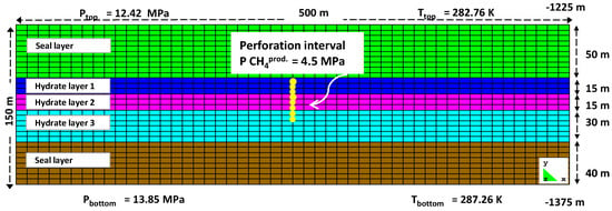
Figure 1.
The gas hydrate reservoir model in Nankai Trough with the perforated production well.
The value of the geothermal gradient was set to 0.03 °C/m, and that of the hydrostatic pressure gradient, to 0.01 MPa/m [16,28]. The water depth was 998 m, with the lower part of the BSR located at 1335 m below the sea floor [23]. The sea-bottom temperature was set to 2.8 °C [28]. Young’s modulus and Poisson’s ratio for all layers were set to 0.5 GPa and 0.25, respectively [29,30,31]. Van Genuchten’s gas entry pressures at zero stress for the two sealing layers and the whole of the hydrate layers were set to 0.196 and 0.0196 MPa, respectively [29,30,31]. Van Genuchten’s exponent, the longitude dispersion factor and the molecular diffusion were 0.457, 11 and 10−10 m, respectively [29,30,31]. The solid phase density, the thermal conductivity and the specific heat of rock were 2150 kg/m3, 4.64 W/(m·K) and 874 J/(kg·K), respectively [29,32]. The hydrate phases were considered as pseudo minerals, and their corresponding reactions, as pseudo reactions. Table 1, Table 2 and Table 3 list the chemical species involved, as well as other properties of each layer and the hydrate layer specifications.

Table 1.
Chemical species in each phase.

Table 2.
Properties of the reservoir model layers. Kv and Kh denote vertical and horizontal permeability, respectively.

Table 3.
Hydrate phase properties.
2.2. Analysis of Simulations
The perforated production well started to produce CH4 at time 0. The induced pressure difference was the main mechanism of the hydrate dissociation.
Figure 2 shows the pressure propagation within the Nankai Trough model reservoir 3, 7 and 16 days after the start of the production. The pressure gradient between the production well and the surroundings was highest during the first 3 days of gas production, gradually becoming less steep at the later stages. As the perforation did not cover the entire third hydrate layer, the pressure draw-down effect was not particularly pronounced in this layer compared to the two others. Additionally, due to a higher permeability in the first hydrate layer, the pressure propagation was more obvious in the first hydrate layer than in the second.
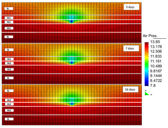
Figure 2.
Pressure changes after 3, 7 and 16 days of production (HLi and SL denote the hydrate layer and the seal layer, respectively).
The hydrate formation and dissociation within RCB was evident from sampling of the porosity changes (taken as changes in the fraction of pore volume filled with fluids). Within this formulation, the hydrate was handled together with other minerals as a solid phase (a pseudo mineral). The reduction of porosity indicated hydrate formation, while the increase in porosity pointed to hydrate dissociation. Figure 3 displays the porosity variation following the production. At early stages, the porosity increased as a result of hydrate dissociation, which was more visible in the first layer. The hydrate dissociation within the second layer was the lowest compared to the other two layers. This may have been caused by its lower permeability, leading to slower propagation of the pressure drop throughout this layer. Additionally, this layer had the lowest hydrate saturation out of all the three hydrate layers. Thus, the amount of dissociated hydrate should have been smaller, resulting in a lower rate of hydrate dissociation. Within the third hydrate layer, the porosity increase was more pronounced at the later stages of production. As this layer had a rather high permeability and hydrate saturation, we expected a faster dissociation of the hydrate in this layer. The fact that hydrate dissociation was slower than in the first layer might have been due to the partial perforation of this layer. However, this layer could have acted as the sealing layer against the underlying water zone invasion. By a continuation of the production and dissociation of the hydrate, the underlying water may have invaded the upper hydrate layers and been produced from the production well. This phenomena would have a negative effect on the gas production efficiency.
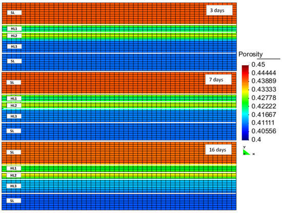
Figure 3.
Porosity changes in the reservoir after 3, 7 and 16 days of production (HLi and SL denote the hydrate layer and the seal layer, respectively).
Figure 4 illustrates the flux of gas towards the production well originating in the gas and hydrate layers. During all stages of production, the gas flux towards the production well was higher in the first layer. Due to a high permeability of this layer, the imposed pressure gradient spread quickly, thus moving the hydrate out of the stability zone. The hydrate saturation in this layer was high. Thus, a large amount of gas had been released and started to flow towards the production well. As pointed out above, the lower permeability in the second layer caused a lower rate for the pressure-drop propagation. Additionally, the hydrate saturation within this layer was low. Therefore, the amount of released gas flowing towards the well was lower. In the third layer, both the permeability and the hydrate saturation were high. However, due to partial perforation, the gas flux in this layer was slightly lower than in the first layer, although it was higher than in the second.
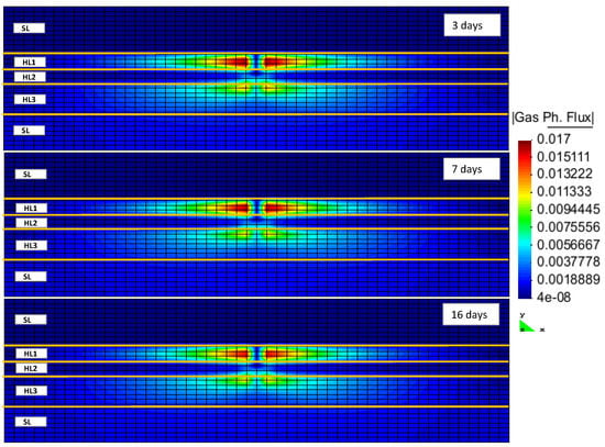
Figure 4.
CH4 gas flux inside the reservoir after 3, 7 and 16 days of production (HLi and SL denote the hydrate layer and the seal layer, respectively).
Hydrate dissociation is an endothermic phenomenon. Hence, the hydrate dissociation rate will be limited by the heat transfer from the surrounding environment. Figure 5 illustrates the heat flux within the reservoir model at different production stages. Different properties of the layers led to different heat fluxes within the reservoir model.
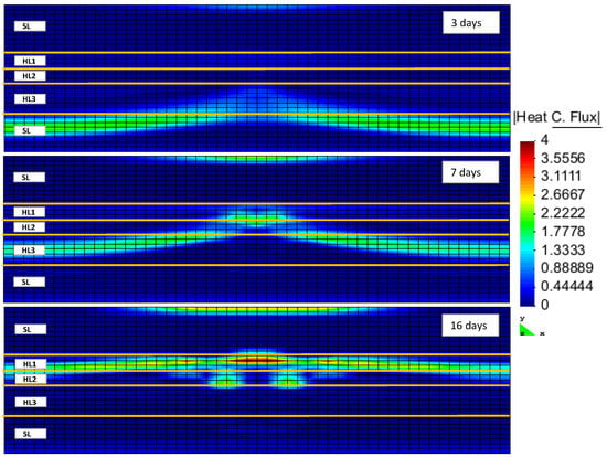
Figure 5.
Heat flux inside the reservoir after 3, 7 and 16 days of production (HLi and SL denote the hydrate layer and the seal layer, respectively).
Hydrate, although softer than quartz or other minerals, is certainly a hard material compared to liquid water or gas. The hydrate as a pseudo mineral was therefore considered a part of the rock matrix. The strength of the hydrate-bearing sediments in the Nankai Trough hydrate field was thought to be relatively high [18], with the gas production through the induced pressure reduction decreasing the hydrate saturation inside the reservoir. The strength of hydrate-bearing sediments is known to be dependent on a number of properties, including temperature, density, strain rate, consolidation stress, and grain size [37]. If we had separately taken the hydrate stiffness into account, together with the variations of geomechanical properties of other minerals, then the hydrate cage occupancy would have played a role in the geomechanical characteristics of the various hydrate pseudo minerals. The reduction of hydrate saturation, as a result of hydrate structure decomposition, reduces the volume of the matrix that carries the overburden load. This may lead to geomechanical instabilities in the form of local subsidence and land slides. RCB is capable of implicitly calculating the geomechanical effects of hydrate dissociation on hydrate-bearing sediments. It requires the evaluation of geomechanical properties during the same time step as the flow calculations. Figure 6 and Figure 7 show the increase and accumulation of effective stress in the vertical and horizontal directions inside the reservoir model as the result of depressurization and hydrate decomposition. Hydrate dissociation reduces the matrix structure’s strength [16].

Figure 6.
Effective stress in Y-direction after 16 days of production (HLi and SL denote the hydrate layer and the seal layer, respectively).

Figure 7.
Effective stress in X-direction after 16 days of production (HLi and SL denote the hydrate layer and the seal layer, respectively).
2.3. Horizontal Well versus Vertical Well
We attempted to compare the difference in the hydrate dissociation rates (equated to the gas production rates) between a vertical well and a horizontal well. In order to perform this comparison, we studied a reservoir model with identical reservoir properties, but different well patterns, as shown in Figure 8. In this model, the production well was horizontal and its perforation interval was 100 m, starting 200 m from the left boundary of the model in the horizontal direction, and ending after 300 m.
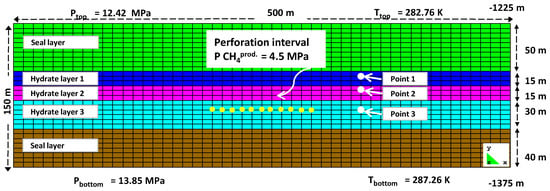
Figure 8.
The gas hydrate reservoir model in Nankai Trough with one horizontally perforated production well.
This model was used to investigate the first 10 days of depressurization-triggered production. As is clearly evident in Figure 9, by keeping all of the reservoir properties constant and at the same time step, the porosity increase in the hydrate layers was slightly greater in the vertical well than in the horizontal well. This may have been explained by the higher permeability in the horizontal rather than vertical direction. Within the horizontal well, the induced pressure-reduction wave propagated slower throughout the reservoir layers due to a lower vertical permeability. This indicated a smaller amount of dissociated hydrate. As a result, the porosity increase was lower than in the case of the vertical well. This difference in porosity variation between the vertical and horizontal wells should have accumulated over time. However, we were unable to confirm this conclusion, as the progress of the simulation had been halted due to divergency problems.
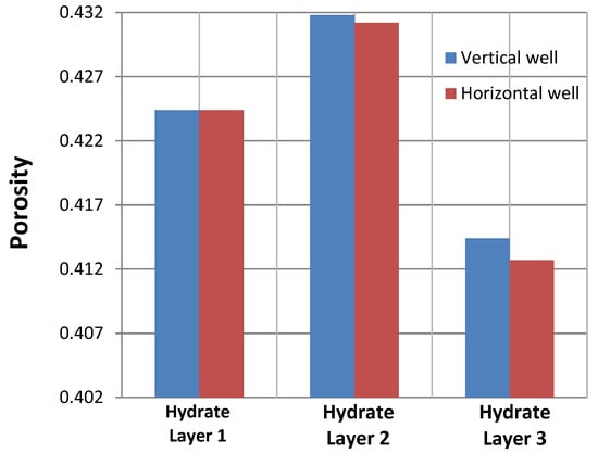
Figure 9.
Comparison of the porosity changes as a result of hydrate dissociation in the horizontal and vertical production wells at nodes 1, 2, and 3, which were located within the first, second and third hydrate layers, respectively.
3. Methods and Procedures
Theory
In the case of local temperature and pressure both being specified by reservoir conditions, even the simplest system containing just water and methane will be incapable of reaching equilibrium between three phases. This is why any equilibrium measurement of properties will keep either only temperature or only pressure fixed, but never both at the same time. As a consequence, hydrates whose guest molecules originate from methane, either initially present as part of a gas mixture or an aqueous phase solute, or trapped in the vicinity of pore walls by adsorbed water layers, will have very different compositions and, thus, different chemical potentials. Each of these hydrates should by rights be considered its own unique phase. The situation will be even further complicated by the presence of additional competing hydrate formers that make equilibrium impossible. Our reservoir simulator only considered those phase transitions that would minimize the Gibbs free energy of the system for the given node at the time point, while allowing for competition amongst the possible hydrate formers. We earlier implemented the following two reactions as routes for methane-hydrate formation in RCB (see [38,39] for details): and . The rest of this section outlines the approach we have taken to implement the second formation route, which involves solute methane, , as the hydrate quest. Classical nucleation theory was used to calculate the kinetic rates for the phase transitions of interest via the application of non-equilibrium thermodynamics to the mass and heat transfer:
where indicates the dissociation/formation/reformation rate of hydrate-type i at node n at time t. The term controls the mass transport; it is estimated via Fick’s Law. Given the constant presence of water in any system involving dissolved methane and hydrates, the phase transition is constrained by the rate of methane diffusion through the aqueous phase. Hence, one can approximate as follows: , where is the mean diffusive flux of CH4 at the interface between the hydrate and water. The variable is the methane fraction gradient at the hydrate side of the interface; stands for the molar density of MH (949.4 mol/m3).
Our group augmented the RCB reservoir simulator by implementing a non-equilibrium thermodynamic package [9,40,41,42] that enables one to specify thermodynamic constraints. At each step of the simulation, three thermodynamics variables (temperature, pressure, and ) were used to determine the hydrate phase transitions highly probable to occur for the current node. In general, the reservoir would ignore the hydrate phase transitions corresponding to positive , as well as unlikely transitions with , thus allowing only phase transitions with negative free energy changes large enough to cross the nucleation barrier. In our case, we simplified the approach even further by setting . Thus, phase transitions were only considered if was negative. The free energy change was calculated as
for every hydrate phase transition; is in the case of hydrate formation, and for dissociation. Superscripts H and (aq.) indicate hydrate and aqueous phases, respectively. Superscript (a.) denotes the mole fraction of in Figure 10 at pressures and temperatures relevant for the node in question.
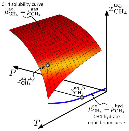
Figure 10.
The maximum CH4 solubility in the aqueous phase (red surface), and the minimum soluble CH4 in the aqueous phase that was required to keep hydrate stable (blue line).
The degree of aqueous phase saturation with respect to dissolved methane, , at a given node was determined by the specifics of the temperature and pressure. The aqueous methane concentration, , falling between the blue line and the red plane in Figure 10, indicates that the aqueous phase was supersaturated with respect to . This would lead to hydrate formation proceeding at the rate determined by Equation (1). If a part of the reservoir model was contacted by brine under-saturated in CH4, the corresponding concentration in Figure 10 would fall under the blue line, indicating the onset of hydrate dissociation.
4. Summary and Conclusions
We used a reactive hydrate reservoir simulator, RCB, to model CH4 production based on a model of the hydrate reservoir of the Nankai Trough field. The model was developed from open geological data available for the field in question. Our results showed that the pressure-drop propagation within the first and the third hydrate layers was faster due to their higher permeabilities and resulting better connections between the pores. Additionally, as hydrate saturation within these two layers was high, the rates of hydrate dissociation and the gas flux towards the production well were higher in these two areas than in the middle section. The second hydrate layer’s contribution in the gas production made it the lowest-producing zone, which could be explained by its lower permeability and hydrate saturation.
Due to a higher permeability in the horizontal direction compared to the vertical direction, designing horizontal wells for gas production may not be the right choice. However, this conclusion may change depending on the placement of the horizontal well with respect to the other layers. Thus, additional analysis will be required to determine the most efficient placement for a horizontal well, depending on permeability, porosity, and hydrate saturation differences in each layer, which result in different hydrate dissociation rates.
Underlying water that presents a high permeability zone could cause problems during production and significantly reduce the efficiency if it invades hydrate zones. Thus, the design of the well, as well as the perforation interval, could have a crucial part in alleviating this problem; sensitivity analysis will be required to determine the optimum design criteria for the production well.
Acknowledgments
We acknowledge the grant and support from the Research Council of Norway and industrial partners through the following projects: CLIMIT: “Safe long term sealing of CO2 in hydrate”, Research Council of Norway, project number: 224857, SSC-Ramore; “Subsurface storage of CO2—Risk assessment, monitoring and remediation”, project number: 178008/I30; FME-SUCCESS, project number: 804831; PETROMAKS: “CO2 injection for extra production”, Research Council of Norway, project number: 801445; PETROMAKS: “CO2 Injection for Stimulated Production of Natural Gas”, Research Council of Norway, project number: 175968; and 230083, STATOIL, under contract 4502354080.
Author Contributions
Qorbani implemented the necessary code changes and extensions needed within the RCB hydrate simulator, as well setting up and running the simulations. She was also the primary author of the manuscript and performed the majority of the analysis of literature review and the simulation results. Kvamme did implement all the changes from ideal gas description to thermodynamics based on Soave-Redlich-Kwong equation of state. Associated changes in various algorithms in order to improve convergence for the modified version was also guided by Kvamme. Kvamme also provided the complete thermodynamic package for hydrate description and thermodynamic changes for all phase transition involved in hydrate formation and dissociation. Kuznetsova provided both language corrections, as well as support in the analysis of the results.
Conflicts of Interest
The authors declare no conflict of interest.
Nomenclature
The following nomenclature is used in this manuscript:
| D | (m2/s) | Diffusion coefficient |
| P | (MPa) | Pressure |
| R | (mol/(m2s)) | Rate |
| T | (K) | Temperature |
| (1) | Mole-fraction | |
| z | (nm) | Distance |
| H | Hydrate phase | |
| (mol/kJ) | Inverse temperature 1/(RT) | |
| (mol/m3) | Molar density | |
| (kJ/mol) | Chemical potential | |
| G | (kJ/mol) | Gibb’s free energy |
Appendix A. RCB simulator package
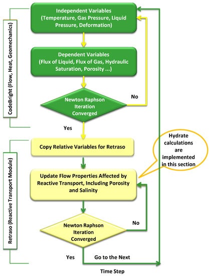
Figure A1.
RCB flowchart.
The current version of the RCB hydrate simulator utilizes a reactive transport algorithm to minimize free energy locally for calculations of most likely phase distributions in a non-equilibrium system. This approach benefits from the possibility to treat each competing hydrate-phase transition as a separate non-equilibrium pseudo reaction by means of an algorithm that minimizes free energy. The algorithm implements an implicit solver to calculate mass flow, heat flow, and changes in geomechanical properties at every time step. The mass fluxes of all components are then corrected by taking into account the composition changes in each phase, and are subsequently handed back to the primary solver in preparation for the next time step. RCB calculates the kinetic rates of hydrate dissociation and reformation by applying the classical nucleation theory. The competition between the two hydrate routes is handled by the non-equilibrium thermodynamic in-house package added to RCB by our group.
As shown in Figure A1, RCB consists of two parts: CodeBright and Retraso [32]. The original purpose of CodeBright was to facilitate the thermo-hydraulic-mechanical analysis of three-dimensional multiphase saline media. Mass balance, energy balance, and geomechanical equations are solved implicitly by the CodeBright part [43,44,45] at every time step. Results from this code are delivered to Retraso [46]. Retraso is a code for solving two-dimensional reactive transport calculations. It solves the relevant geochemical reactions, including hydrate pseudo-reactions, at every time step and at every node. From relevant available mass and thermodynamic conditions, Retraso determines which reactions are applicable within each node.
In the coupled code, RCB, the CodeBright module, calculates the flow properties (Darcy flux of liquid and/or gas, saturation, temperature, density, etc.) and passes it to the Retraso module for the calculation of reactive transport. After updating the flow properties’ (i.e., porosity and permeability) output, this code is transferred back to the CodeBright part to calculate the next time step [32]. RCB simulates flow in the range from diffusion to advection and dispersion. Thus, RCB is able to handle flow in all regions of the porous media inside the reservoir, including the low permeability regimes of hydrate-filled regions. Liquid and gas advective fluxes are calculated using Darcy’s Law, while intrinsic permeability and retention curves are calculated using Kozney’s correlation [47] and the Van Genuchten model [48], respectively. The Van Genuchten model and generalized power law are applied to estimate the relative permeabilities of liquids and gasses, respectively. Diffusive and dispersive mass fluxes are obtained through Fick’s law, and Fourier’s law is used to calculate dispersive and conductive fluxes of heat in the simulator.
It should also be noted that RCB was originally developed as a hydrogeological simulator, and allows for the integration of mass flux, heat flux, and stress-development within its basic module. The mass flow is updated in the Retraso part via reactions (which also applies for pseudo-reactions for hydrate-phase transitions). The associated heat is added as a sink or source term, similarly to for the mass of each component, which is also updated on the same basis. The associated heat transport is modeled by a simple “lumped” heat conductivity model, in a similar way as National Energy Technology Laboratory (NETL) and other groups have previously reported [49]. A more detailed description is given in the Appendix of [31], as well as in [32]. RCB handles spatial and temporal discretization using finite elements and finite differences, respectively. The equations to be solved are non-linear, and are solved using the Newton–Raphson algorithm. Due to faster hydrate-phase transitions relative to mineral precipitation and dissociation, we take advantage of implicit geomechanical calculations inside CodeBright, which makes it possible to avoid time lags between geomechanical calculations and the rest of the balance equations. The possibility of selecting a wide range of species inside the Retraso code enables us to define hydrates as pseudo minerals, with their phase transitions treated as pseudo reactions. We chose to use the Soave-Redlich-Kwong (SRK) equation of state [50] for CO2 and CH4 gases, as it is sufficiently accurate within our pressure and temperature range [10].
RCB has previously been modified for CO2 storage in the form of CO2 hydrate [31] and CH4 gas production from methane hydrate (MH) reservoirs via the depressurization technique [39] in several separate implementations. The rate constant in hydrate-phase transitions was obtained from phase field theory (PFT) [51]. To visualize the final results from RCB, we utilized the GID post-processor [52].
References
- Lerche, I.; Bagirov, E. Guide to gas hydrate stability in various geological settings. Mar. Pet. Geol. 1998, 15, 427–437. [Google Scholar] [CrossRef]
- Wilcox, W.I.; Carson, D.B.; Katz, D.L. Natural Gas Hydrates; Paull, C.K., Dillon, W.P., Eds.; Geophysical Monograph Series; American Geophysical Union: Washington, DC, USA, 2001. [Google Scholar]
- Gas Hydrates, a Review of an Unconventional Gas Resource. Available online: GasChem.com (accessed on 3 October 2015).
- Bollmann, M.; Bosch, T.; Colijn, F.; Ebinghaus, R.; Froese, R.; Güssow, K.; Khalilian, S.; Krastel, S.; Körtzinger, A.; Langenbuch, M.; et al. World Ocean Review 1 (WOR1). Living with the Oceans: A Report on the State of the World’s Oceans; Technical Report; World Ocean Review; Maribus: Hamburg, Germany, 2010. [Google Scholar]
- Sloan, E.; Koh, C. Clathrate Hydrates of Natural Gases, 3rd ed.; CRC Press: Boca Raton, FL, USA, 2007. [Google Scholar]
- Graue, A.; Kvamme, B.; Baldwin, B.; Stevens, J.; Howard, J.J.; Aspenes, E.; Ersland, G.; Husebo, J.; Zornes, D. MRI visualization of spontaneous methane production from hydrates in sandstone core plugs when exposed to CO2. SPE J. 2008, 13, 146–152. [Google Scholar] [CrossRef]
- Ersland, G.; Husebø, J.; Graue, A.; Kvamme, B. Transport and storage of CO2 in natural gas hydrate reservoirs. Energy Procedia 2009, 1, 3477–3484. [Google Scholar] [CrossRef]
- Kvamme, B.; Graue, A.; Buanes, T.; Kuznetsova, T.; Ersland, G. Storage of CO2 in natural gas hydrate reservoirs and the effect of hydrate as an extra sealing in cold aquifers. Int. J. Greenh. Gas Control 2007, 1, 236–246. [Google Scholar] [CrossRef]
- Kvamme, B.; Qasim, M.; Baig, K.; Kivelä, P.H.; Bauman, J. Hydrate phase transition kinetics from phase field theory with implicit hydrodynamics and heat transport. Int. J. Greenh. Gas Control 2014, 29, 263–278. [Google Scholar] [CrossRef]
- Kvamme, B.; Graue, A.; Buanes, T.; Kuznetsova, T.; Ersland, G. Effects of solid surfaces on hydrate kinetics and stability. Geol. Soc. Lond. Spec. Publ. 2009, 319, 131–144. [Google Scholar] [CrossRef]
- Buanes, T.; Kvamme, B.; Svandal, A. Computer simulation of hydrate growth. J. Cryst. Growth 2006, 287, 491–494. [Google Scholar] [CrossRef]
- Ohgaki, K.; Takano, K.; Sangawa, H.; Matsubara, T.; Nakano, S. Methane exploitation by carbon dioxide from gas hydrates. Phase equilibria for CO2-CH4 mixed hydrate system. J. Chem. Eng. Jpn. 1996, 29, 478–483. [Google Scholar] [CrossRef]
- Gamwo, I.K.; Liu, Y. Mathematical modeling and numerical simulation of methane production in a hydrate reservoir. Ind. Eng. Chem. Res. 2010, 49, 5231–5245. [Google Scholar] [CrossRef]
- Moridis, G. Numerical studies of gas production from methane hydrates. SPE J. 2003, 8, 359–370. [Google Scholar] [CrossRef]
- Fujii, T.; Suzuki, K.; Takayama, T.; Tamaki, M.; Komatsu, Y.; Konno, Y.; Yoneda, J.; Yamamoto, K.; Nagao, J. Geological setting and characterization of a methane hydrate reservoir distributed at the first offshore production test site on the Daini-Atsumi Knoll in the eastern Nankai Trough, Japan. Mar. Pet. Geol. 2015, 66, 310–322. [Google Scholar] [CrossRef]
- Zhou, M.; Soga, K.; Xu, E.; Uchida, S.; Yamamoto, K. Numerical study on eastern Nankai Trough gas hydrate production test. In Proceedings of the Offshore Technology Conference, Houston, TX, USA, 5–8 May 2014. [Google Scholar]
- Tsuji, Y.; Ishida, H.; Nakamizu, M.; Matsumoto, R.; Shimizu, S. Overview of the MITI Nankai Trough wells: A milestone in the evaluation of methane hydrate resources. Resour. Geol. 2004, 54, 3–10. [Google Scholar] [CrossRef]
- Takahashi, H.; Tsuji, Y. Multi-well exploration program in 2004 for natural hydrate in the Nankai-Trough offshore Japan. In Proceedings of the Offshore Technology Conference, Houston, TX, USA, 2–5 May 2005. [Google Scholar]
- Fujii, T.; Nakamizu, M.; Tsuji, Y.; Namikawa, T.; Okui, T.; Kawasaki, M.; Ochiai, K.; Nakamizu, M.; Takano, O. Methane-hydrate occurrence and saturation confirmed from core samples, eastern Nankai Trough, Japan. AAPG Mem. 2009, 89, 385–400. [Google Scholar]
- Saeki, T.; Fujii, T.; Inamori, T.; Kobayashi, T.; Hayashi, M.; Nagakubo, S.; Takano, O. Extraction of methane hydrate concentrated zone for resource assessment in the eastern Nankai Trough, Japan. In Proceedings of the Offshore Technology Conference, Houston, TX, USA, 5–8 May 2008. [Google Scholar]
- Kida, M.; Jin, Y.; Watanabe, M.; Konno, Y.; Yoneda, J.; Egawa, K.; Ito, T.; Nakatsuka, Y.; Suzuki, K.; Fujii, T.; Nagao, J. Chemical and crystallographic characterizations of natural gas hydrates recovered from a production test site in the eastern Nankai Trough. Mar. Pet. Geol. 2015, 66, 396–403. [Google Scholar] [CrossRef]
- Fujii, T.; Saeki, T.; Kobayashi, T.; Inamori, T.; Hayashi, M.; Takano, O.; Takayama, T.; Kawasaki, T.; Nagakubo, S.; Nakamizu, M.; et al. Resource assessment of methane hydrate in the eastern Nankai Trough, Japan. In Proceedings of the Offshore Technology Conference, Houston, TX, USA, 5–8 May 2008. [Google Scholar]
- Yamamoto, K.; Terao, Y.; Fujii, T.; Ikawa, T.; Seki, M.; Matsuzawa, M.; Kanno, T. Operational overview of the first offshore production test of methane hydrates in the Eastern Nankai Trough. In Proceedings of the Offshore Technology Conference, Houston, TX, USA, 5–8 May 2014. [Google Scholar]
- Noguchi, S.; Shimoda, N.; Takano, O.; Oikawa, N.; Inamori, T.; Saeki, T.; Fujii, T. 3-D internal architecture of methane hydrate-bearing turbidite channels in the eastern Nankai Trough, Japan. Mar. Pet. Geol. 2011, 28, 1817–1828. [Google Scholar] [CrossRef]
- Fujii, T.; Noguchi, S.; Takayama, T.; Suzuki, K.; Yamamoto, K.; Saeki, T. Site selection and formation evaluation at the 1st offshore methane hydrate production test site in the eastern Nankai Trough, Japan. In Proceedings of the 75th EAGE Conference & Exhibition-Workshops, London, UK, 10–13 June 2013. [Google Scholar]
- Yamamoto, K.; Inada, N.; Kubo, S.; Fujii, T.; Suzuki, K.; Nakatsuka, Y.; Ikawa, T.; Seki, M.; Konno, Y.; Yoneda, J.; Nagao, J.; et al. A pressure coring operation and on-board analyses of methane hydrate-bearing samples. In Proceedings of the Offshore Technology Conference, Houston, TX, USA, 5–8 May 2014. [Google Scholar]
- Suzuki, K.; Takayama, T.; Fujii, T. Density structure report from logging-while-drilling data and core data at the first offshore gas production test site on Daini-Atsumi Knoll around eastern Nankai Trough. Mar. Pet. Geol. 2015, 66, 388–395. [Google Scholar] [CrossRef]
- Sun, J.; Ning, F.; Zhang, L.; Liu, T.; Peng, L.; Liu, Z.; Li, C.; Jiang, G. Numerical simulation on gas production from hydrate reservoir at the 1st offshore test site in the eastern Nankai Trough. J. Nat. Gas Sci. Eng. 2016, 30, 64–76. [Google Scholar] [CrossRef]
- Chejara, A.; Kvamme, B.; Vafaei, M.T.; Jemai, K. Theoretical studies of methane hydrate dissociation in porous media using RetrasoCodeBright simulator. Energy Procedia 2012, 18, 1533–1540. [Google Scholar] [CrossRef]
- Vafaei, M.T.; Kvamme, B.; Chejara, A.; Jemai, K. Nonequilibrium modeling of hydrate dynamics in reservoir. Energy Fuels 2012, 26, 3564–3576. [Google Scholar] [CrossRef]
- Vafaei, M.; Kvamme, B.; Chejara, A.; Jemai, K. A new reservoir simulator for studying hydrate dynamics in reservoir. Int. J. Greenh. Gas Control 2014, 23, 12–21. [Google Scholar] [CrossRef]
- Saaltink, M.W.; Ayora, C.; Olivella, S. User’s Guide for RetrasoCodeBright (RCB); Institute of Earth Sciences Jauma Almera, Spanish Research Council (CSIC): Barcelona, Spain, 2005. [Google Scholar]
- Moridis, G.J.; Reagan, M.T.; Kim, S.J.; Seol, Y.; Zhang, K. Evaluation of the gas production potential of marine hydrate deposits in the Ulleung basin of the Korean east sea. SPE J. 2009, 14, 759–781. [Google Scholar] [CrossRef]
- Waite, W.F.; Stern, L.A.; Kirby, S.H.; Winters, W.J.; Mason, D.H. Simultaneous determination of thermal conductivity, thermal diffusivity and specific heat in sI methane hydrate. Geophys. J. Int. 2007, 169, 767–774. [Google Scholar] [CrossRef]
- Anderson, G.K. Enthalpy of dissociation and hydration number of methane hydrate from the Clapeyron equation. J. Chem. Thermodyn. 2004, 36, 1119–1127. [Google Scholar] [CrossRef]
- Yoon, J.H.; Yamamoto, Y.; Komai, T.; Haneda, H.; Kawamura, T. Rigorous approach to the prediction of the heat of dissociation of gas hydrates. Ind. Eng. Chem. Res. 2003, 42, 1111–1114. [Google Scholar] [CrossRef]
- Winters, W.J.; Pecher, I.A.; Waite, W.F.; Mason, D.H. Physical properties and rock physics models of sediment containing natural and laboratory-formed methane gas hydrate. Am. Mineral. 2004, 89, 1221–1227. [Google Scholar] [CrossRef]
- Qorbani, K.; Kvamme, B. Non-equilibrium simulation of CH4 production from gas hydrate reservoirs through the depressurization method. J. Nat. Gas Sci. Eng. 2016, 35, 1544–1554. [Google Scholar] [CrossRef]
- Chejara, A.; Kvamme, B.; Vafaei, M.T.; Jemai, K. Simulations of long term methane hydrate dissociation by pressure reduction using an extended RetrasoCodeBright simulator. Energy Convers. Manag. 2013, 68, 313–323. [Google Scholar] [CrossRef]
- Kvamme, B. Kinetics of hydrate formation from nucleation theory. Int. J. Offshore Polar Eng. 2002, 12, 256–263. [Google Scholar]
- Kvamme, B. Droplets of dry ice and cold liquid CO2 for self-transport of CO2 to large depths. In Proceedings of the The Eleventh International Offshore and Polar Engineering Conference, Stavanger, Norway, 17–22 June 2001. [Google Scholar]
- Kvamme, B.; Kuznetsova, T.; Kivelæ, P.H.; Bauman, J. Can hydrate form in carbon dioxide from dissolved water? Phys. Chem. Chem. Phys. PCCP 2013, 15, 2063–2074. [Google Scholar] [CrossRef] [PubMed]
- Olivella, S.; Gens, A.; Carrera, J. CodeBright User’s Guide; Universitat Politecnicade Catalunya and Institutode Ciencias de la Tierra; CSIS: Barcelona, Spain; E.T.S.I. Caminos: Canalesy Puertos, Spain, 1997. [Google Scholar]
- Olivella, S.; Carrera, J.; Gens, A.; Alonso, E.E. Nonisothermal multiphase flow of brine and gas through saline media. Transp. Porous Media 1994, 15, 271–293. [Google Scholar] [CrossRef]
- Olivella, S.; Gens, A.; Carrera, J.; Alonso, E. Numerical formulation for a simulator (CODE_BRIGHT) for the coupled analysis of saline media. Eng. Comput. 1996, 13, 87–112. [Google Scholar] [CrossRef]
- Saaltink, M.W.; Batlle, F.; Ayora, C.; Carrera, J.; Olivella, S. RETRASO, a code for modeling reactive transport in saturated and unsaturated porous media. Geol. Acta 2004, 2, 235–251. [Google Scholar]
- Kozeny, J. Ueber kapillare leitung des wassers im boden. Sitzungsber. Akad. Wiss. 1927, 136, 271–306. [Google Scholar]
- Van Genuchten, M.T. A closed-form equation for predicting the hydraulic conductivity of unsaturated soils. Soil Sci. Soc. Am. J. 1980, 44, 892–898. [Google Scholar] [CrossRef]
- NETL Software. Available online: http://www.netl.doe.gov/research/oil-and-gas/software (accessed on 2 October 2015).
- Soave, G. Equilibrium constants from a modified Redlich-Kwong equation of state. Chem. Eng. Sci. 1972, 27, 1197–1203. [Google Scholar] [CrossRef]
- Baig, K. Phase Field Theory Modeling of CH4 and CO2 Fluxes from Exposed Natural Gas Hydrate Reservoirs. Master’s Thesis, The University of Bergen, Bergen, Norway, 2009. [Google Scholar]
- CIMNE, International Center for Numerical Methodes in Engineering. Available online: http://gid.cimne.upc.es/ (accessed on 21 July 2015).
© 2017 by the authors. Licensee MDPI, Basel, Switzerland. This article is an open access article distributed under the terms and conditions of the Creative Commons Attribution (CC BY) license (http://creativecommons.org/licenses/by/4.0/).