Article

Thermal Response Testing Results of Different Types of Borehole Heat Exchangers: An Analysis and Comparison of Interpretation Methods

1
Department of Industrial Engineering—Applied Physics Section, University of Padova, Via Venezia 1, 35131 Padova, Italy
2
Department of Geoscience, University of Padova, Via Gradenigo 6, 35131 Padova, Italy
3
GeoZentrum Nordbayern, Lehrstuhl für Geologie, Friedrich-Alexander-Universität Erlangen-Nürnberg, Schloßgarten 5, 91054 Erlangen, Germany
4
Red Srl, Viale dell’Industria 58/B, 35129 Padova, Italy
5
Hydra Srl, Via Imperiale 6, Traghetto di Argenta, 44011 Ferrara, Italy
6
Rehau AG & Co, Ytterbium 4, 91058 Erlangen-Eltersdorf, Germany
7
CNR-ISAC, Corso Stati Uniti 4, 35127 Padova, Italy
*
Author to whom correspondence should be addressed.
Energies 2017, 10(6), 801; https://doi.org/10.3390/en10060801
Submission received: 13 April 2017 / Revised: 7 June 2017 / Accepted: 10 June 2017 / Published: 13 June 2017
(This article belongs to the Special Issue Low Enthalpy Geothermal Energy)

Abstract

:
The design phase of ground source heat pump systems is an extremely important one as many of the decisions made at that time can affect the system’s energy performance as well as installation and operating costs. The current study examined the interpretation of thermal response testing measurements used to evaluate the equivalent ground thermal conductivity and thus to design the system. All the measurements were taken at the same geological site located in Molinella, Bologna (Italy) where a variety of borehole heat exchangers (BHEs) had been installed and investigated within the project Cheap-GSHPs (Cheap and efficient application of reliable Ground Source Heat exchangers and Pumps) of the European Union’s Horizon 2020 research and innovation program. The measurements were initially analyzed in accordance with the common interpretation based on the first-order approximation of the solution for the infinite line source model and then by utilizing the complete solutions of both the infinite line and cylinder source models. An inverse numerical approach based on a detailed model that considers the current geometry of the BHE and the axial heat transfer as well as the effect of weather on the ground surface was also used. Study findings revealed that the best result was generally obtained using the inverse numerical interpretation.

1. Introduction

Ground source heat pump (GSHP) systems are well established means to heat and cool buildings given their greater environmental friendliness and higher energy efficiency with respect to those of other systems [1]. The closed loop ground borehole heat exchanger (BHE) is the most widely used configuration [2]. The energy performance of that type’s entire system depends on the thermal performance of the ground heat exchangers which, in turn, depends on the geometry of the BHE, the layout of the borehole field and, obviously, on ground thermal properties. Particular attention must, therefore, be paid to these variables during the design phase.
Data necessary to design a borehole field includes the type of the ground at the installation site as well as the thermal load profile. Ground thermal properties are particularly important to calculate the total length of BHEs. The main parameter is the equivalent thermal conductivity which, for typical sedimentary unconsolidated materials, can range from 1 to 3 W/(m K); the thermal capacity is instead a less variable factor [1.5–2.5 MJ/(m3 K)]. Preliminary measurements of ground thermal conductivity can be obtained from lithology information available for the installation site and from data reported in the literature. This approach, which may prove quite inaccurate, should be used only when the borehole field simply consists of a few BHEs. When the size of the plant-system increases, knowledge of precise ground thermal properties is important to avoid under- or over-sizing the total borehole length which could cause a fall in energy efficiency over the years in the former case and high installation costs in the latter one.
Several analytical models to analyze the heat transfer between the borehole heat exchanger and the surrounding ground are present in literature [3]. However, the most common procedure to evaluate the equivalent ground thermal conductivity is the Thermal Response Test (TRT) [4,5], a simplification of the infinite line source model [6] which considers the first-order approximation of the exponential integral function of the fluid temperatures measured. TRT measurements must be taken under defined boundary conditions for this interpretation; if any of its assumptions are invalid, the interpretation will lead to an error in the final outcome [7]. Characterized by simplicity and less computational time, the approach, however, neglects axial heat transfer. Given its simplified approach, it can, in any case, be utilized only for long boreholes with small diameters and to analyze long-term thermal behavior. To this purpose, Conti [8] recently carried out analyses in order to develop dimensionless criteria to decide the appropriate analytical solution, concluding that the finite line source model [9] can be used in a wide range of space and time scales. However, also the finite line source model does not consider the effect of the borehole thermal capacitance and the variation of the climate conditions at the ground surface which can significantly affect the thermal behavior of shallow ground heat exchangers.
The cylindrical heat source method is another analytical approach, which was developed by Carslaw and Jaeger [6], that can be used to consider the finite diameter of the BHE. It represents an exact solution of a cylindrical heat source placed in an infinite homogeneous medium, the ground. In this case as well, the properties of the ground are assumed constant, the axial heat transfer is neglected, and a perfect contact between the cylinder wall and the ground is assumed.
Another method to evaluate the equivalent ground thermal properties is the inverse numerical procedure which uses the TRT measurements as input data [10,11]. A more accurate value of the equivalent ground thermal conductivity can be obtained if the numerical model used for that purpose considers the effects of the weather on the earth surface and axial heat transfer as well as the borehole thermal capacitance since these aspects affect the real heat exchange between the heat carrier fluid and the surrounding ground, especially when the borehole depth is low.
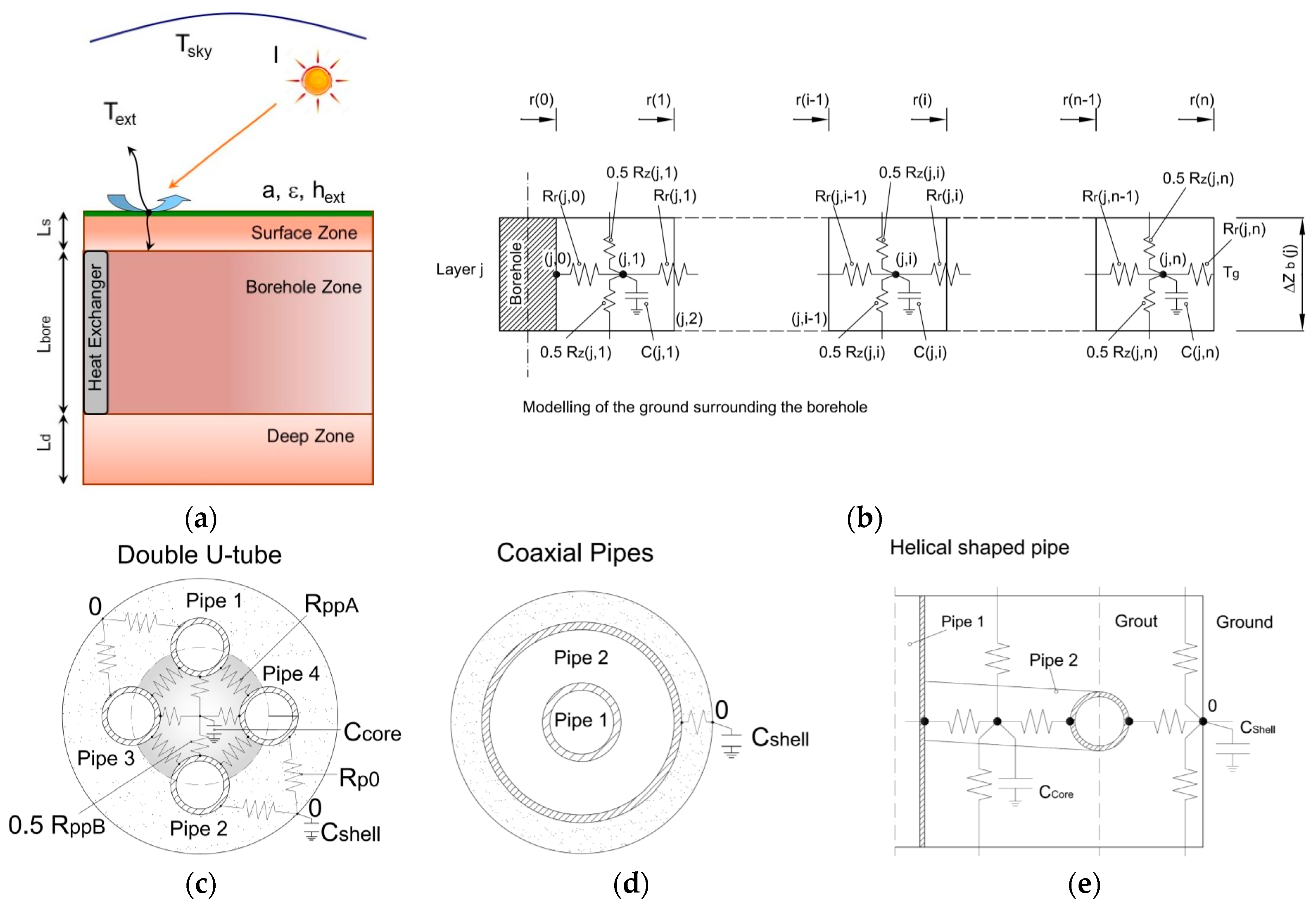
Other, secondary input data that should be used to design a GSHP system is the type of BHE that will be installed. The most commonly used type in practice is the U-tube loop with a single or double U-tube configuration; the former is widely utilized in the United States and Canada while the latter is more common in Europe. Another important model type is the coaxial pipe heat exchanger, which consists of two concentric pipes that can be constructed in different materials. When the outer pipe is in stainless steel, a piling methodology can be used to install the system whenever the ground is clearly an alternation of coarse grain materials such as clay and sand, a solution that would imply reduced installation times.
Many authors have recently been investigating the thermal performances of these BHEs in the attempt to improve the energy performance of heat pumps as well as to reduce the initial cost of installing the boreholes. Wood et al. [12] compared the energy performance of two loop designs for use with a GSPH of an energy pile installation or a conventional borehole system. Using an experimental facility, two different scenarios were investigated: one with the single U-pipe and the other with a coaxial pipe. They reported that the coaxial loop did not add any performance benefit against a conventional single U-tube configuration. They also concluded that the coaxial loop could potentially reduce drilling costs and facilitate installation.
Aydin and Sisman [13] conducted an experimental, computational investigation on the effects of multi U-tube boreholes from the point of view of thermal performance (i.e., heat transfer rate per borehole length unit) and of costs. The effect of the number of pipes was, in particular, investigated. The authors concluded that the 2U and 3U-tube configurations had, respectively, 14% and 25% better performance with respect to a single U-tube. From a cost point of view, they concluded that the best solution in their specific Turkish economy was a 2U-tube BHE. Also Conti et al. [14] compared the single and double U-tube heat exchangers in terms of both heat transfer effectiveness and borehole thermal resistance. Cimmino [15], recently, developed an analytical tool in order to evaluate the thermal behavior of ground heat exchangers with multiple U-tubes; his model, however, does not consider the borehole thermal capacity. Investigating the effect of the drillhole diameter on the thermal performance of a double U-tube ground heat exchanger, Luo et al. [16] reported that thermal performance increased with larger drill hole diameters.
Kurevija et al. [17] investigated the effect of grout thermal conductivity on the long-term energy efficiency of an operating GSHP. Carrying out an energy analysis of a real retrofitting project of a plant system with 16 boreholes spaced 6 m apart, they reported that thermally enhanced grouts are preferable when the ground has high conductivity properties. Zanchini et al. [18] focused on improving the thermal performance of long coaxial BHEs using detailed models implemented by commercial software [19]. Their results indicated that the effect of thermal short-circuiting is more relevant when there are higher grout and soil thermal conductivity levels. Those authors also investigated the effect of fluid mass flow rate, and they published [20] an article reporting the results of a study evaluating the effects of flow direction on the performance of small coaxial BHEs.
Saez Blazquez et al. [21], who investigated the thermal performance of single/double U-tube and helical shaped pipe heat exchangers using a variety of laboratory tests, concluded that the best thermal performance was found for the latter. Dehghan et al. [22] carried out a parametric investigation of helical ground heat exchangers in order to define the parameters that influence the thermal performance of an entire GSHP system. Basing their study on 3D numerical simulations, the authors identified the main parameters of helical ground heat exchanger fields, and simulations were carried out for four different configurations. Performance losses due to thermal interactions linked to different BHE spacing and pitch magnitude effects of the helix on the heat transfer ratio were analyzed. The authors concluded that 100% of the variation in the geometrical properties of the helix (pitch and diameter) can affect the thermal performance by about 10%. On the other hand, the minimum distance between the helix appears to be about 7 m to keep the performance loss less than 10%.
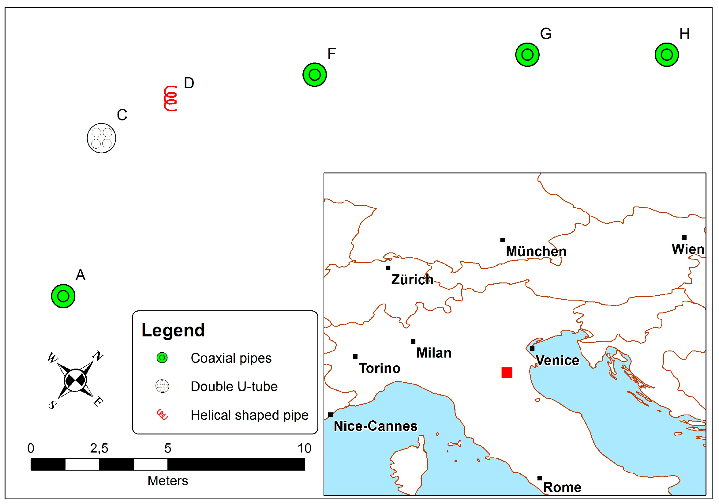
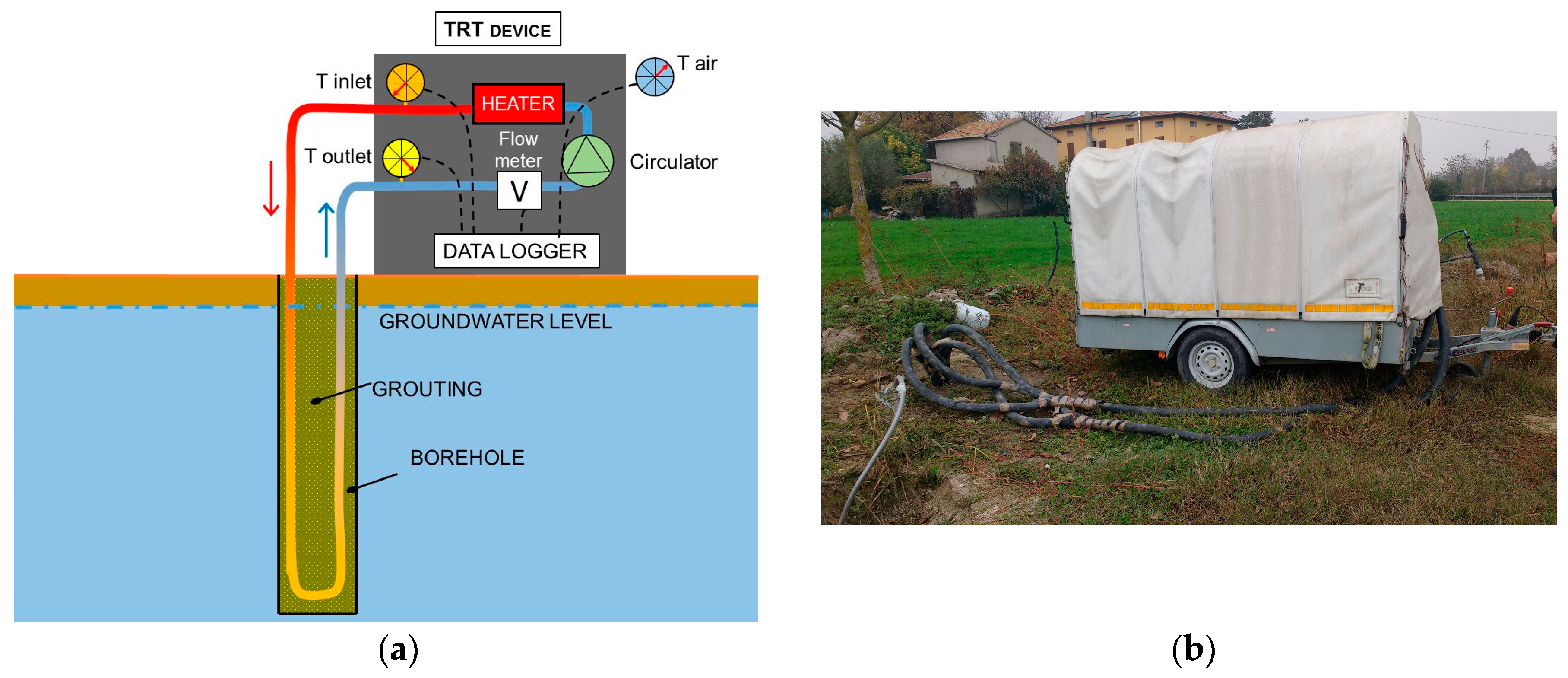
The current study set out to analyze TRTs to evaluate the equivalent ground thermal conductivity, which were carried out on different BHEs located at a single site using both standard interpretations and complete analytical solutions of the infinite line and cylinder source models. The inverse numerical approach was also investigated making use of a detailed numerical model which considers the climatic conditions at the ground surface, axial heat transfer into both the grouting material and ground, and also the borehole thermal capacity. In detail, TRTs were carried out on coaxial pipe, double U-tube and helical shaped pipe BHEs. After the description of the test site and models used (Section 2), the results of the analysis of the thermal response testing measurements on different borehole heat exchangers are presented (Section 3).

2. Methods

2.1. Test Site

The test site was located in Molinella, which is situated in the alluvial Po Valley, in the Bologna province in the Emilia-Romagna region. The site is bound to the North and West by the Alps, to the South by the Northern Apennines, and the land opens to the East to meet the Adriatic Sea. Extending over approximately 30,000 km2, the Po Valley is the largest alluvial plain in Western Europe. Alluvial plains are relatively flat areas composed of alluvium sediments; the rivers, which transport water and sediments from higher to lower grounds, eventually reach the sea. During floods coarse-grained sediment is deposited close to streams and fine-grained sediment may be deposited at greater distances. The alternation of coarse (gravel and sand) and fine-grained (silt and clay) sediment materials which form sand dikes or sills with a predominantly horizontal development is characteristic of alluvial deposits. They can thus be described as a dominantly layered structure, and the thermal and hydrogeological properties of these unconsolidated materials show a horizontal versus a vertical anisotropy. The ground heat exchangers that were studied here had been installed in a Late Pleistocenic and Holocenic sandy and clay alluvial sequence. The seven types of BHEs situated in the test area are arranged as illustrated in Figure 1 and they are listed in Table 1.
There were four coaxial pipe ground heat exchangers (Boreholes A, F, G and H) whose characteristics are outlined in Table 2. Boreholes F, G and H all have the same length (i.e., 50 m); Borehole A is 96 m long. The inner pipes of all of the BHEs were made of high density polyethylene (i.e., HDPE). The outer pipes of Boreholes A, G and H were in stainless steel (i.e., AISI 304) and that of Borehole F was constructed in polyvinyl chloride (i.e., PVC). The inner pipes of Boreholes A and H were thermally insulated with approximately 4 mm of insulation material in order to decrease the thermal short-circuit with the annular zone of the ground heat exchanger. The variation in the borehole diameter of each BHE depended on the diameter of the outer pipe. Due to type of the drilling technique employed, grouting material was used only for Borehole F, in addition to the common double U-tube heat exchanger. Boreholes A, G and H were, in fact, installed by pushing the stainless steel outer tube of the coaxial ground heat exchanger into the ground using a penetrometer. As standard water drilling techniques were used for Borehole F, grouting material was used to fill the space between the outer pipe and the borehole wall.
There was also a standard 50 m long double U-tube borehole heat exchanger (Borehole C); its characteristics are outlined in Table 3. Finally, there was one shallow, 15 m long helical shaped pipe ground heat exchanger (Borehole D) whose characteristics are outlined in Table 4; in this case the pipe was made of crosslinked poly-ethylene (i.e., Pe-Xa) co-extruded with a thin aluminum and poly-ethylene foil to give it stability and dead folded to the tube in order to maintain the pitch between turns during the installation of the helical shaped pipe inside the bore. To this purpose, in order to make easier the installation of the helical shaped pipe in the test site, it was stretched to lower the helix’s diameter and, consequently, this involved an increase of the pitch between the turns and a reduction of the pipe length installed.
A continuous 100 m long sediment core with a 101 mm diameter was collected during drilling in November 2016 and a description of its contents is outlined in Table 5. The coring was analyzed from the bibliographic point of view. The calculation was based on the layer thickness weighted mean, which is a rough estimate, as it does not take into account the influence of the different layers and the water content. The thermal conductivity values were based on literature data outlined in the standard VDI 4640 [23], using the wet lithology as a reference point. The equivalent thermal conductivity values on 15 m, 50 m and 100 m that were calculated were respectively equal to 1.5, 1.7 and 1.82 W/(m K).

2.2. The Thermal Response Test

Thermal response testing (TRT) was carried out on each BHE using test equipment that was developed in accordance with the American Society of Heating, Refrigerating and Air-Conditioning Engineers (ASHRAE) guidelines [24]. The equipment consisted of a closed loop including the BHE (Figure 2). The TRT was performed by imposing a constant heat-injection rate to the heat-carrier fluid flowing inside the BHE. In this case, seven electric resistances, each with a power of 1.5 kW and combined into a tank, were used for heating; the total heat-injection rate that could be delivered was about 10.5 kW. The stainless steel tank, which was thermally insulated, could contain up to 100 L of water. The heat transfer fluid was moved by a thermally insulated circulator.
During the first testing phase, the electrical resistances were switched off in order to assess the undisturbed ground temperature; the heat transfer fluid was moved by the circulator, and the inlet and outlet fluid temperatures at the top of the borehole were measured and recorded at one second intervals for at least half an hour. The electrical resistances were then switched on and standard thermal response testing was carried out; the following parameters were measured and recorded at 15 s time intervals for 72 h:
  • the outside air temperature;
  • the inlet and outlet fluid temperature to the borehole;
  • the volumetric fluid flow rate;
  • the electric power absorbed by the electrical resistances.
The temperatures were measured using PT1000 Class A resistance thermometers (accuracy of ± (0.15 + 0.002 × the reading temperature)), and the volumetric fluid flow rate was measured by means of an electromagnetic sensor (accuracy of ±0.2%). The specific heat-injection rate per unit of borehole length equal to about 60 W/m was set for each BHE. The helical shaped pipe for which only one electrical resistance of 1.5 kW was switched on corresponded to a specific heat-injection rate of about 100 W/m. The heat-carrier fluid was pure water and its mass flow rate was set so that the inlet and outlet temperature difference was equal to about 3 °C in each BHE.

2.3. Thermal Response Test Analysis

The TRT measurements were analyzed in order to evaluate the equivalent ground thermal conductivity using the following interpretation methods:
  • the infinite line source model (ILSM);
  • the infinite cylinder source model (ICSM);
  • the inverse numerical approach.
In this analysis the volumetric ground heat capacity was assumed constant and equal to 2.20 MJ/(m3 K) considering the lithology data scoring.

2.3.1. The Infinite Line Source Model

A standard procedure based on the infinite line source model is usually used to evaluate the ground thermal conductivity. As is known, the model furnishes the temperature in an infinite homogenous body which is heated along an ideal thin infinite line with a constant heating rate q′ assumed to be released as a constant per unit time and length and only moving along a radial direction. According to this model, the temperature at time τ and the distance r from the line is [6]:
T ( r , τ ) T g = q 4 π λ E i ( r 2 4 a τ )
The effect of the finite diameter of the borehole is not considered in this model; in fact, the approach based on this theory assumes that the thermal process within the borehole is a nearly steady-state condition and only a thermal resistance is included between the heat-carrier fluid and the borehole wall, usually called borehole thermal resistance Rb. Finally, the mean fluid temperature Tfm within the BHE can be calculated according to the following relationship:
T f m ( τ ) = q 4 π λ E i ( r b 2 4 a τ ) + q R b + T g
The exponential integral E i ( r 2 4 a τ ) in Equation (1) can be approximated with the following relationship for large values of (a τ/r2):
E i ( r 2 4 a τ ) ln ( 4 a τ r 2 ) γ
As a consequence, Equation (2) becomes:
T f m ( τ ) q 4 π λ ( ln ( 4 a τ r b 2 ) γ ) + q R b + T g
When (/r2) > 5 the error of the approximation of Equation (3) is within 10%. Equation (4) represents the common interpretation of the infinite line source model used by technicians to evaluate the equivalent ground thermal conductivity by means of TRT measurements; here this approach is called the simplified infinite line source model (S-ILSM). In this case, the mean temperature of the inlet and outlet heat-carrier fluid measured at the top of the borehole heat exchanger is plotted against the natural logarithm of time, obtaining a linear relation whose slope k is linked to the equivalent ground thermal conductivity (λeq) by means of the following equation:
λ e q = q 4 π k
where q′ is the constant heat injection rate per unit length of the borehole used as an input during the TRT.
The equivalent ground thermal conductivity (λeq) was also evaluated using the complete infinite line source model (i.e., Equation (2)) (here called ILSM) which was implemented by Matlab [25]; the λeq value was calculated minimizing the root mean square error (RMSE) (Equation (6)) between the experimental mean fluid temperature (Tm,TRT) and the corresponding value calculated (Tm,calc) using the analytical model. This approach was also used for the other models presented in the following sections.
R M S E = i = 1 n s t e p ( T m , T R T , i T m , c a l c , i ) 2 n s t e p

2.3.2. The Infinite Cylinder Source Model

The infinite cylinder source model can be used to analyze the finite diameter of the heat source or sink. The BHE is approximated in this model to an infinite cylinder that releases a constant heat rate along its length over time; also in this case the heat transfer takes place only along the radial direction. The solution of the infinite cylinder source model is expressed by the following Equation (7), making use of Equations (8) and (9) [6]:
T ( r , τ ) T g = q λ G ( z , p ) z = a τ r 2 p = r r b
G ( z , p ) = 1 π 2 0 f ( β ) d β
f ( β ) = ( e z β 2 1 ) J 0 ( p β ) Y 1 ( β ) Y 0 ( p β ) J 1 ( β ) β 2 ( J 1 2 ( β ) + Y 1 2 ( β ) )
where J0, J1, Y0, and Y1 are the Bessel functions of the first and second kind.
As for the infinite line source model, the mean fluid temperature can then be calculated using r = rb:
T f m ( τ ) = q λ G ( a τ r b 2 , 1 ) + q R b + T g
The infinite cylinder source model was also assessed using Matlab and the equivalent ground thermal conductivity (λeq) was evaluated comparing the analytical result and the measured value of the mean fluid temperature using the same procedure (Equation (6)) described above for the infinite line source model.

2.3.3. The Inverse Numerical Approach

Using the TRT measurements as input data, ground thermal conductivity was also evaluated utilizing the inverse numerical procedure by means of the CaRM tool [26,27,28]. The current BHE was modelled by CaRM taking into consideration the real geometry, the materials, the connections and, if appropriate, the thermal properties of the grouting material. Figure 3 shows the general modelling approach used by CaRM, which considers heat transfer both along the depth direction (i.e., axial heat transfer) and the radial direction as well as the effect of the weather on the earth’s surface in terms of both thermal convection and short-long wave radiation. This is particularly important in the case of a shallow BHE because the ground temperature along the first 15–20 m is not constant due to the climatic conditions at that specific location, as it can be found with the well-known analytical equation of heat diffusion within a semi-infinite solid when the surface temperature is a harmonic function of time [6]. As is shown in Figure 3a, the ground is divided into three basic zones: the surface, the borehole, and the deep zones. In the ground between the earth’s surface and above the borehole (i.e., surface zone) and beneath the lower end of the borehole (i.e., the deep zone), heat transfer is modelled in one dimension (in the depth direction). In the ground surrounding the borehole and also in the grouting material (i.e., the borehole zone) heat transfer takes place along both the radial and depth directions. Each zone is then divided into several sub-regions that are modelled with thermal resistances and lumped capacitances (see Figure 3b). Figure 3c–e shows the modelling details of the double U-tube, coaxial pipe and helical shaped pipe heat exchangers.
The effects of the thermal capacitance of the grouting material and the heat-carrier fluid inside the pipes were considered in the model. The convection and short-long wave radiation was modelled on the earth’s surface. The constant undisturbed ground temperature (Tg) was found at the extreme opposite side, at the highest depth, as a boundary condition. CaRM calculates the temperature distribution within the ground, the grouting material and the heat-carrier fluid as a function of position and time; the heat flow can then be computed based on the relationship between the heat flow and the gradient temperature. Details on the model are outlined in [26].
Real weather data collected by the weather station near Molinella were used. The initial temperature of each thermal node in the control volume was set in accordance with Kusuda and Achenbach’s model [29], which takes into consideration the ground’s thermal diffusivity (ag), the location’s climatic parameters, and the current time. The undisturbed ground temperature (Tg) was set to the result from the TRT measurements conducted on the longest borehole (Borehole A) that was equal to approximately 15 °C and applied 30 m beneath the lower end of the borehole heat exchanger.
The thermal properties of the grouting material outlined in Table 2, Table 3 and Table 4 were considered. The thermal resistance between the pipe and the borehole wall is an important parameter that affects the BHE’s thermal behavior. It mainly depends on the conduction thermal resistance of the outer pipe for coaxial and helical heat exchangers and, if present, the grouting material; both can be calculated via the well-known formula of the hollow cylinder. The thermal resistances between the pipes (RppA and RppB) of the double U-tube heat exchanger and between the pipes and the bore wall (Rp0) (Figure 3c) were instead calculated using a commercial software based on the finite element method [19] and then used as input for CaRM. These values are outlined in Table 6.
The borehole heat exchangers were modelled in the current study with the following mesh parameters:
  • The ground zones were divided into vertical sub-regions each of which with a thickness Δz(j) equal to 0.25 m;
  • Each vertical sub-region of the borehole zone was divided into 20 annular regions from the borehole axis to the maximum radius (rmax) which was equal to 10 m.
The following parameters were applied at ground level and assumed to be constant for the entire simulation time:
  • absorptance (a): 0.7;
  • emittance (ε): 0.9;
  • specific convection thermal resistance (Rext): 0.04 (m2 K)/W.
The numerical simulations were carried out using the inlet fluid temperature, the mass flow rate of the heat-carrier fluid, and weather data as input. The outlet fluid temperature was then calculated using the CaRM tool and the mean fluid temperature was compared with the corresponding experimental value based on the TRT measurements. Ground thermal conductivity was modified in order to minimize the RMSE (Equation (5)). Using this procedure, the ground thermal conductivity was determined taking into consideration both the radial and axial heat transfer as well as climatic conditions. The time interval for simulation was set to every 60 s.

3. Results and Discussion

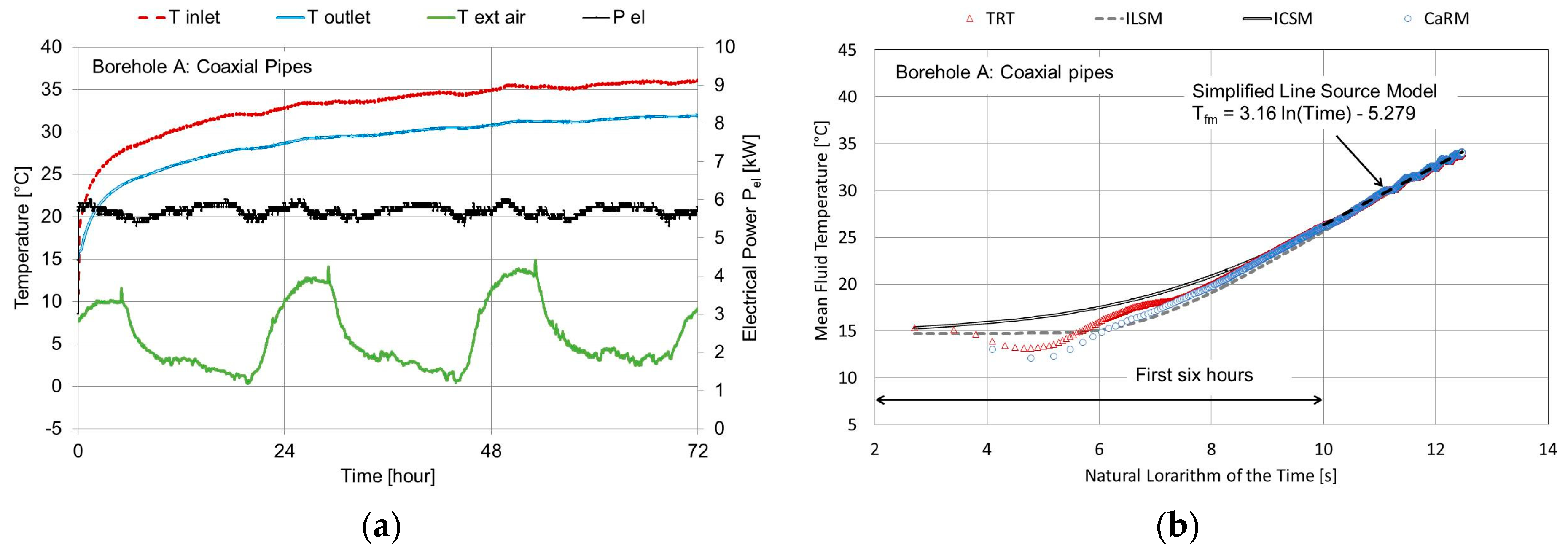
TRT results and their analysis are outlined in this section. As Borehole A, a coaxial BHE, was the longest one (i.e., 96 m long) in the test area, it was used as a reference point for the site’s geological characterization. Figure 4a outlines the TRT measurements of that BHE. In addition, Figure 4b shows the analysis carried out in accordance with the common interpretation of the TRT measurements based on the infinite line source approach used to evaluate the equivalent ground thermal conductivity (λeq) which resulted equal to approximately 1.49 W/(m K) at a depth of 96 m. This value was lower than that (i.e., 1.82 W/(m K)) calculated using information obtained from the data sheets of the drilling operations and values outlined by the standard VDI 4640 [23]. The uncertainty analysis of the TRT measurements involved a global error of the equivalent thermal conductivity of approximately ±0.15 W/(m K). The fluid volume within that BHE was approximately 286 L; the effect of the thermal capacity of the heat-carrier fluid can be seen in the first section where the mean fluid temperature profile is plotted (Figure 4b); it initially fell and then started to rise. As can be seen, the greatest difference between the analytical results and the measured values was found during the first six hours of testing; test results were, instead, nearly equivalent over the long-term. The results of CaRM are in agreement also with the short-term experimental values since the model takes into consideration the borehole thermal capacity.
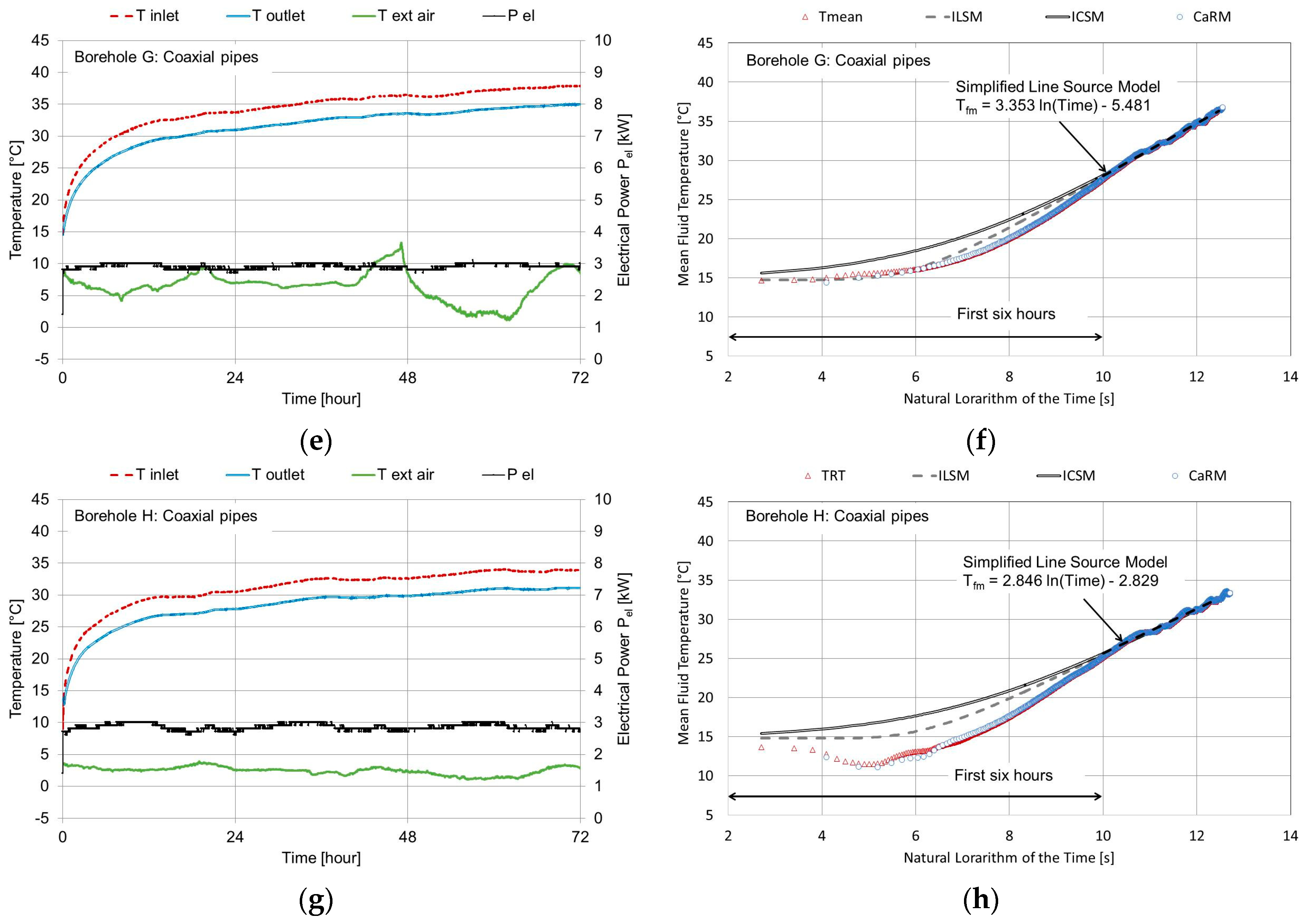
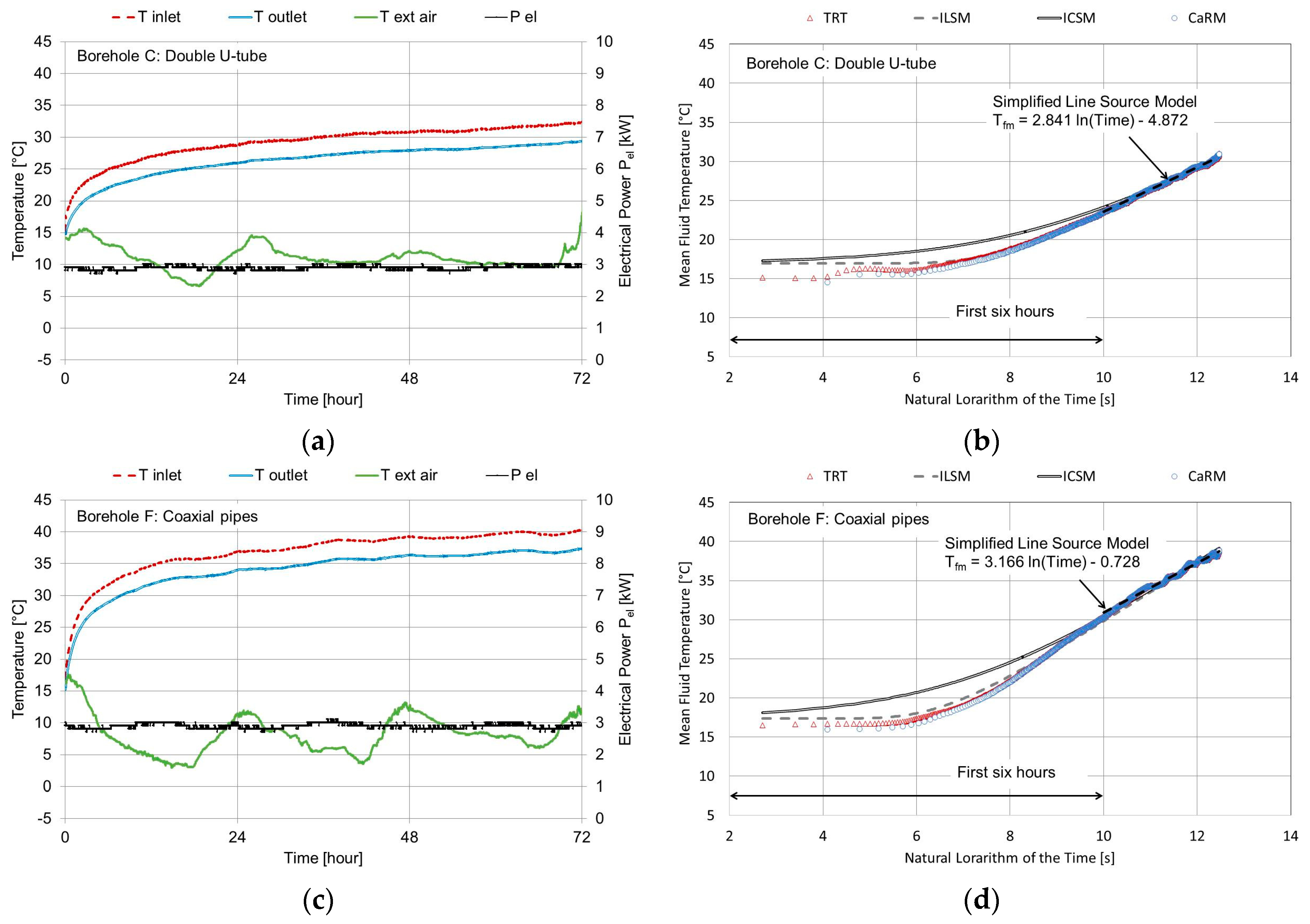
Figure 5 shows the TRT measurements for the 50 m long boreholes. Figure 5a,b refers to the double U-tube, Figure 5c,d to Borehole F, Figure 5e,f to Borehole G, and Figure 5g,h to Borehole H. The fluid volume is 106 L for the double U-tube; it is 114, 76 and 73 L for Boreholes F, G and H, respectively. The volume fluid flow rate was the same for those BHEs and equal to 2.39 × 10⁻⁴ m3/s.
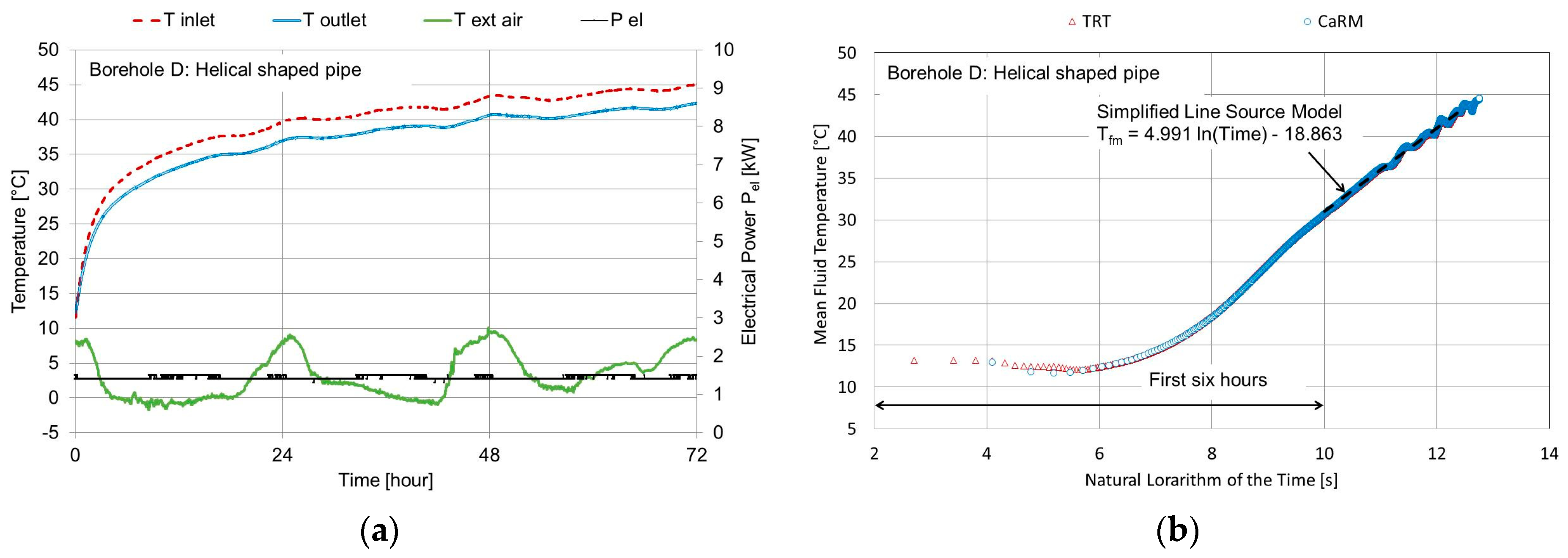
Figure 6 outlines the TRT measurements of the 15 m long helical shaped pipe heat exchanger (Borehole D). The effect of the axial heat conduction cannot be neglected in that particular BHE given its shallow depth and large diameter (i.e., 0.4 m). This explains why the common interpretation based on the infinite line source model (S-ILSM) involves an error in evaluating the equivalent ground thermal conductivity: according to that model, which is the usual one adopted by technicians to calculate the variable, heat transfer takes place only along the radial direction, in which case the result was approximately 1.39 W/(m K). According to the inverse numerical approach, the result was approximately 1.2 W/(m K). The value produced by the numerical procedure was clearly lower since the imposed heat transfer rate moves along both radial and axial directions; it is instead considered a single value in the radial direction by the S-ILSM. As can be seen in Figure 6b, the mean fluid temperature starts from a value that is lower than that for the 50 m long boreholes (Figure 5) since the effect of the weather on the ground temperature is higher for the shallow depth of 15 m. The infinite line and cylinder source models were not applied to this BHE because the hypotheses were not clearly satisfied.
Table 7 outlines the equivalent ground thermal conductivity calculated using the common interpretation (S-ILSM), infinite line (ILSM) and cylinder (ICSM) source models as well as the inverse solution via CaRM tool for each BHE investigated. As can be seen, the result of the simplified line source model (S-ILSM) was higher than that found using the complete solution of the infinite line source model (ILSM) since the contribution of the first six hours was neglected. The equivalent thermal conductivity of the ground from the ICSM was less than that via ILSM; in fact, in the ICSM the heat was released at the borehole radius and, consequently, did not take into consideration the contribution of the bore filling material. The minimum RMSE value was found by means of the CaRM, and this can be seen also in Figure 4, Figure 5 and Figure 6. As can be observed in Table 7, the equivalent ground thermal conductivity outlined using the interpretation of the infinite line source approach ranged from 1.35 W/(m K) for Borehole G to 1.60 W/(m K) for Borehole C, which is located at the same site and has the same depth. The two BHEs were spaced only about 15 m away from one another but the ground layers could have been diversified leading to different equivalent thermal conductivity values. This result highlights the importance of carrying out TRT measurements at different positions in a borehole field especially when there are several borehole heat exchangers so that any difference in the ground composition can be identified and the mean equivalent thermal conductivity to use during the design process can be found.
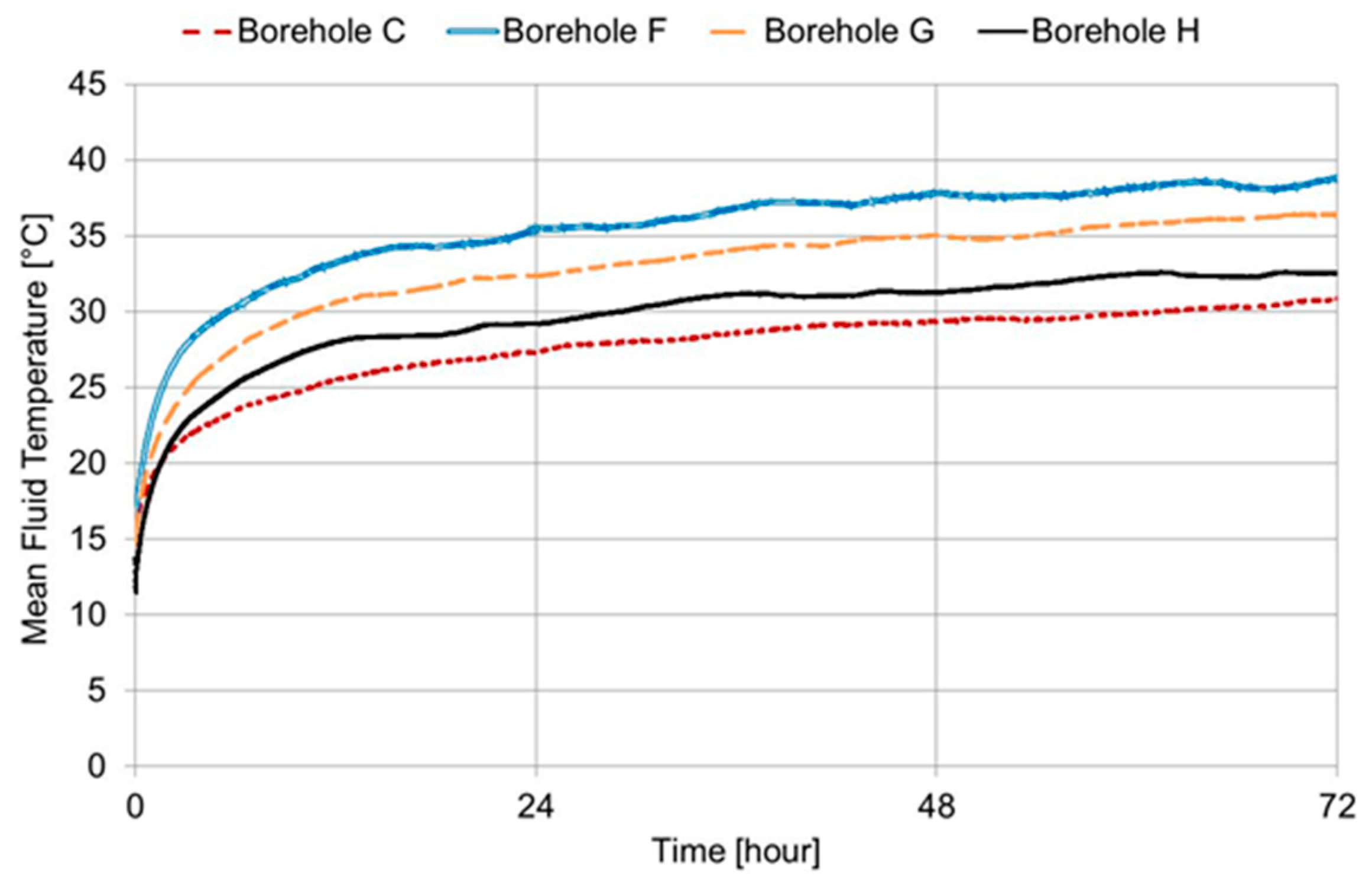
The TRT of the 50 m long BHEs was carried out using both the same heat-injection rate and fluid mass flow rate. As a consequence, the thermal behavior of the BHEs under constant heat injection rate could also be evaluated. The differences between the inlet and outlet mean fluid temperature profiles of the four BHE were thus compared (Figure 7). As can be seen, after 72 operating hours under a constant heat injection rate, the double U-tube heat exchanger liberated the same heat load with the lowest temperature difference between the heat-carrier fluid inside the pipes and the surrounding ground. The thermal behavior of Borehole H was better than that of Borehole G since it has a larger outer diameter (60.3 versus 50 mm). Borehole F, which had the largest outer diameter (i.e., 101 mm), needed, instead, a higher temperature difference to liberate the heat rate since its thermal resistance was higher than that of Borehole H (see Table 6); this result largely depended on the material in which the pipes were constructed (PVC for Borehole F and stainless steel for Borehole H).
In order to compare the thermal performance, the global heat transfer coefficient can be calculated as follows:
U b = q ( T f , m T g )
At the end of the thermal response testing (i.e., after 72 h under constant heat injection rate) the Ub coefficient was approximately 3.7, 2.4, 2.6 and 3.2 W/(m K) for Borehole C, F, G and H, respectively.

4. Conclusions

The current study analyzed the interpretation of thermal response testing using analytical and numerical models. The common method, which uses the first-order approximation of the infinite line source model, was compared with the complete solution of the infinite line and cylinder source models. The inverse numerical procedure was also investigated using a detailed model.
The equivalent thermal conductivity provided by literature data depending on the ground type was about 20% higher than that found using the common interpretation of the TRT measurements conducted on the 96 m long BHE. In addition, the thermal response testing interpretation showed that in that same area the equivalent thermal conductivity ranged from approximately 1.35 to 1.62 W/(m K) for the same BHE depth. The minimum misfit between the experimental and calculated values of the mean fluid temperature was found using the inverse numerical procedure by means of the CaRM simulation tool which considers important phenomena that affect the thermal behavior of the borehole heat exchanger, e.g., the weather conditions at the ground surface, axial heat transfer and borehole thermal capacity. The inverse numerical approach clearly depends on the accuracy of the model used. The main assumption of the analytical models is a constant heat load, which is not easy to replicate in the practice; on the other hand, CaRM tool is able to consider the fluctuations of the heat load and, consequently, the transient thermal behavior. In addition, as the CaRM tool can analyze the short-term behavior of the ground heat exchanger, a lower time span of the thermal response testing can be used, involving a decrease of the test’s costs.
Test results revealed that the thermal behavior of the BHEs when a constant and long-term heat injection rate is applied significantly depends on their total exchanging surface and hence size. When intermittent operating modes of the ground source heat pump system are set, the thermal capacity (of both grouting material and heat carrier fluid) and thermal resistance of the borehole heat exchanger are surely key parameters that could affect the seasonal energy efficiency of the entire system. Therefore, demonstration cases will be realized within the European Cheap-GSHPs project in order to evaluate the energy efficiency of the entire ground source heat pump system under variable operating modes. Considering in particular the coaxial stainless steel pipes, together with energy performance, it is anyway important to consider its easier installation, thanks to the use of a piling methodology that leads to lower costs.

Acknowledgments

This work has received funding from the European Union’s Horizon 2020 research and innovation program under grant agreement No. 657982.

Author Contributions

Matteo Cultrera and Antonio Galgaro conceived, designed and performed the experimental site and measurements. Angelo Zarrella and Giuseppe Emmi implemented the methodology and analyzed the results. All Authors provided technical and theoretical support. Angelo Zarrella and Giuseppe Emmi wrote the manuscript and all Authors reviewed and approved the final version.

Conflicts of Interest

The authors declare no conflict of interest.

Nomenclature

aThermal diffusivity (m2/s), surface absorptance (-)
CVolume heat capacity (J/K)
DDiameter (m)
hextConvection heat transfer coefficient at ground level (W/(m2 K))
IIncident solar radiation (W/(m2)
iGround discretization index in radial direction
jGround discretization index in vertical direction
kSlope of the curve
LLength (m)
LboreBorehole length (m)
nNumber of the steps (-)
PPower (W)
qHeat rate per unit length (W/m)
rRadius (m)
rmaxRadius from axis borehole beyond which the undisturbed ground is considered (m)
RThermal resistance (K/W)
RbBorehole thermal resistance ((m K)/W)
RextConvection thermal resistance at ground level per unit area ((m2 K)/W)
Rp0Thermal resistance between the pipe and borehole wall ((m K)/W)
RppAThermal resistance between adjacent pipes ((m K)/W)
RppBThermal resistance between the opposite pipes ((m K)/W)
TTemperature (K)
TextExternal air temperature (K)
TgUndisturbed ground temperature (K)
TskySky temperature (K)
UGlobal heat transfer coefficient (W/(m K))

Greek Symbols

βIntegration variable (-)
εSurface emittance (-)
λThermal conductivity (W/(m K))
γEuler’s constant
τTime (s)
τDiscretization time step (s)
zLength of control volume in vertical direction (m)

Subscripts

bBorehole, borehole zone
dDeep zone
calcCalculated
eqEquivalent
elElectrical
fFluid
gGround
mMean
rRadial direction
sSurface zone
zDepth direction

Abbreviations

AISIAmerican Iron and Steel Institute
HDPEHigh density polyethylene
ICSMInfinite cylinder source model
ILSMInfinite line source model
PVCPolyvinyl chloride
RMSERoot mean square error
S-ILSMSimplified infinite line source model
TRTThermal response test

References

  1. Lucia, U.; Simonetti, M.; Chiesa, G.; Grisolia, G. Ground-source pump system for heating and cooling: Review and thermodynamic approach. Renew. Sustain. Energy Rev. 2017, 70, 867–874. [Google Scholar] [CrossRef]
  2. Sarbu, L.; Sebarchievici, C. General review of ground-source heat pump systems for heating and cooling of buildings. Energy Build. 2014, 70, 441–454. [Google Scholar] [CrossRef]
  3. Li, M.; Lai, A.C. Review of analytical models for heat transfer by vertical ground heat exchangers (GHEs): A perspective of time and space scales. Appl. Energy 2015, 151, 178–191. [Google Scholar] [CrossRef]
  4. Gehlin, S. Thermal Response Test: Method, Development and Evaluation. Ph.D. Thesis, Lulea University of Technology, Lulea, Sweden, 2002. [Google Scholar]
  5. Austin, W.A. Development of an In Situ System for Measuring Ground Thermal Properties. Master’s Thesis, Oklahoma State University, Stillwater, OK, USA, 1998. [Google Scholar]
  6. Carslaw, H.S.; Jaeger, J.C. Conduction of Heat in Solids; Claremore Press: Oxford, UK, 1959. [Google Scholar]
  7. Witte, H.J.L. Error analysis of thermal response tests. Appl. Energy 2013, 109, 302–311. [Google Scholar] [CrossRef]
  8. Conti, P. Dimensionless Maps for the Validity of Analytical Ground Heat Transfer Models for GSHP Applications. Energies 2016, 9, 890. [Google Scholar] [CrossRef]
  9. Zeng, H.Y.; Diao, N.R.; Fang, Z.H. A finite line-source model for boreholes in geothermal heat exchangers. Heat Transf. Asian Res. 2002, 31, 558–567. [Google Scholar] [CrossRef]
  10. Zarrella, A.; Emmi, G.; Zecchin, R.; De Carli, M. An appropriate use of the thermal response test for the design of energy foundation piles with U-tube circuits. Energy Build. 2017, 134, 259–270. [Google Scholar] [CrossRef]
  11. Pasquier, P. Stochastic interpretation of thermal response test with TRT-SInterp. Comput. Geosci. 2015, 75, 73–87. [Google Scholar] [CrossRef]
  12. Wood, C.J.; Liu, H.; Riffat, S.B. Comparative performance of ‘U-tube’ and ‘coaxial’ loop designs for use with a ground source heat pump. Appl. Therm. Eng. 2012, 37, 190–195. [Google Scholar] [CrossRef]
  13. Aydın, M.; Sisman, A. Experimental and computational investigation of multi U-tube boreholes. Appl. Energy 2015, 145, 163–171. [Google Scholar] [CrossRef]
  14. Conti, P.; Testi, D.; Grassi, W. Revised heat transfer modeling of double-U vertical ground-coupled heat exchangers. Appl. Therm. Eng. 2016, 106, 1257–1267. [Google Scholar] [CrossRef]
  15. Cimmino, M. Fluid and borehole wall temperature profiles in vertical geothermal boreholes with multiple U-tubes. Renew. Energy 2016, 96, 137–147. [Google Scholar] [CrossRef]
  16. Luo, J.; Rohn, J.; Bayer, M.; Priess, A. Thermal efficiency comparison of borehole heat exchangers with different drillhole diameters. Energies 2013, 6, 4187–4206. [Google Scholar] [CrossRef]
  17. Kurevija, T.; Macenić, M.; Borović, S. Impact of grout thermal conductivity on the long-term efficiency of the ground-source heat pump system. Sustain. Cities Soc. 2017, 31, 1–11. [Google Scholar] [CrossRef]
  18. Zanchini, E.; Lazzari, S.; Priarone, A. Improving the thermal performance of coaxial borehole heat exchangers. Energy 2010, 35, 657–666. [Google Scholar] [CrossRef]
  19. Users Guide, COMSOL Multiphysics, version 3.5; COMSOL AB: Stockholm, Sweden, 2008.
  20. Zanchini, E.; Lazzari, S.; Priarone, A. Effects of flow direction and thermal short-circuiting on the performance of small coaxial ground heat exchangers. Renew. Energy 2010, 35, 1255–1265. [Google Scholar] [CrossRef]
  21. Sáez Blázquez, C.; Farfán Martín, A.; Martín Nieto, I.; Carrasco García, P.; Sánchez Pérez, L.S.; González-Aguilera, D. Efficiency Analysis of the Main Components of a Vertical Closed-Loop System in a Borehole Heat Exchanger. Energies 2017, 10, 201. [Google Scholar] [CrossRef]
  22. Dehghan, B.; Sisman, A.; Aydin, M. Parametric investigation of helical ground heat exchangers for heat pump applications. Energy Build. 2016, 127, 999–1007. [Google Scholar] [CrossRef]
  23. Verein Deutscher Ingenieure-VDI. VDI 4640 Part 1. In Thermal Use of the Underground: Fundamentals, Approvals, Environmental Aspects; Verein Deutscher Ingenieure: Düsseldorf, Germany, 2010. [Google Scholar]
  24. American Society of Heating, Refrigerating, and Air-Conditioning Engineers (ASHRAE). ASHRAE Handbook: HVAC Applications, Geothermal Energy; ASHRAE: Atlanta, GA, USA, 2011; Chapter 34. [Google Scholar]
  25. MATLAB, version 7.10.0; The MathWorks Inc.: Natick, MA, USA, 2010.
  26. Zarrella, A.; Pasquier, P. Effect of axial heat transfer and atmospheric conditions on the energy performance of GSHP systems: A simulation-based analysis. Appl. Therm. Eng. 2015, 78, 591–604. [Google Scholar] [CrossRef]
  27. Zarrella, A.; Emmi, G.; De Carli, M. Analysis of operating modes of a ground source heat pump with short helical heat exchangers. Energy Convers. Manag. 2015, 97, 351–361. [Google Scholar] [CrossRef]
  28. Capozza, A.; Zarrella, A.; De Carli, M. Long-term analysis of two GSHP systems using validated numerical models and proposals to optimize the operating parameters. Energy Build. 2015, 93, 50–64. [Google Scholar] [CrossRef]
  29. Kusuda, T.; Achenbach, P.R. Earth temperatures and thermal diffusivity at selected stations in the United States. ASHRAE Trans. 1965, 71, 61–74. [Google Scholar]
Figure 1. Testing site located in Molinella, slightly southwest of Venice.
Energies 10 00801 g001
Figure 2. Thermal response test equipment: (a) scheme; (b) measurements in the test site.
Energies 10 00801 g002
Figure 3. The CaRM modelling approach: (a) overview; (b) ground; (c) double U-tube; (d) coaxial pipes; (e) helical shaped pipe.
Energies 10 00801 g003
Figure 4. Thermal response test of the Borehole A which was 96 m long: (a) Test measurements; (b) Analysis with analytical and numerical models.
Energies 10 00801 g004
Figure 5. Thermal response test of Boreholes C, F, G and H which were all 50 m long: (a,c,e,g) Test measurements of Boreholes C, F, G and H respectively; (b,d,f,h) Analysis with analytical and numerical models of Boreholes C, F, G and H respectively.
Energies 10 00801 g005aEnergies 10 00801 g005b
Figure 6. Thermal response test of the Borehole D which was 15 m long: (a) Test measurements; (b) Analysis with analytical and numerical models.
Energies 10 00801 g006
Figure 7. Comparison of the mean fluid temperature of the 50 m long borehole heat exchangers.
Energies 10 00801 g007
Table 1. List of the borehole heat exchangers assessed.
BoreholeTypeLength [m]Borehole Diameter [mm]Notes
ACoaxial pipes9676.1Outer pipe in stainless steel.
CDouble U-tube50125Pipes in HDPE.
FCoaxial pipes50101Outer pipe in PVC with grouting material.
GCoaxial pipes5050Outer pipe in stainless steel.
HCoaxial pipes5060.3Outer pipe in stainless steel.
DHelical shaped pipe15400Helical pipe in PE-Xa and aluminium with grouting material.
Table 2. Characteristics of the coaxial borehole heat exchangers.
BoreholeBoreholeBoreholeBorehole
AFGH
Inner Pipe (Inlet)
Material HDPEHDPEHDPEHDPE
Thermal conductivity[W/(m K)]0.400.400.400.40
Outside diameter[mm]32.032.025.032.0
Inside diameter[mm]26.026.021.026.0
Insulation foam thickness[mm]4.0--4.0
Insulation foam thermal conductivity[W/(m K)]0.09--0.09
Outer Pipe (Outlet)
Material AISI 304PVCAISI 304AISI 304
Thermal conductivity[W/(m K)]16.00.2016.016.0
Outside diameter[mm]76.163.050.060.3
Inside diameter[mm]68.957.046.053.1
Borehole diameter[mm]76.1101.050.060.3
Borehole length[m]96.050.050.050.0
Thermal conductivity of the grout[W/(m K)]-1.6--
Thermal diffusivity of the grout[m2/s]-0.70 × 10−6--
Table 3. Characteristics of the double U-tube borehole heat exchangers (Borehole C).
PipeUnitDescription
Material HDPE
Thermal conductivity[W/(m K)]0.40
Outside diameter[mm]32.0
Inside diameter[mm]26.0
Spacing between the pipes (centre-to-centre)[mm]90.0
Number of pipes-4
Connection-Parallel
Borehole diameter[mm]125.0
Borehole length[m]50.0
Thermal conductivity of the grout[W/(m K)]1.6
Thermal diffusivity of the grout[m2/s]0.70 × 10−6
Table 4. Characteristics of the helical shaped pipe heat exchanger (Borehole D).
PipeUnitDescription
Material PE-Xa—aluminium—PE co-extruded
Thermal conductivity[W/(m K)]0.38
Outside diameter[mm]20.0
Inside diameter[mm]14.2
Length of helical pipe per unit bore length[m/m]1.15
Outer diameter of the helix[mm]220.0
Borehole diameter[mm]400.0
Pitch between the turns[mm]600.0
Borehole length[m]15.0
Thermal conductivity of the grout[W/(m K)]1.84
Thermal diffusivity of the grout[m2/s]0.86 × 10−6
Table 5. The simplified composition of the coring.
LayerDepth [m]Description
FromTo
100.9Topsoil
20.91.5Silty clay
31.57Silt
479.8Silty clay
59.812.3Peat
612.312.5Sand
712.515.6Silty clay
815.621.1Clay
921.127Silty clay
102728.6Silt
1128.633.5Silty clay
1233.538.1Silt
1338.138.6Clay
1438.642.4Silty clay
1542.446.8Sand
1646.855Silty clay
175556.6Clay
1856.657.5Silty clay
1957.557.6Peat
2057.660Clay
216064.5Silty clay
2264.566.4Clay
2366.470.1Silty sand
2470.172.2Silt
2572.272.7Clay
2672.774.2Silty clay
2774.276.9Sandy silt
2876.980.2Clay
2980.281.3Sandy silt
3081.382.9Sand
3182.987.1Clay
3287.187.7Sandy silt
3387.788.9Sand
3488.990.3Sandy silt
3590.3100Sand
Table 6. Thermal resistances of the borehole heat exchangers.
Thermal Resistance [(m K)/W]Borehole
ACFGHD
Outer pipe of coaxial BHE0.001-0.0800.0010.001-
Grouting material--0.047--0.053
Between adjacent pipes in double U-tube (RppA)-0.613----
Between opposite pipes in double U-tube (RppB)-0.832----
Between pipe and borehole wall in double U-tube (Rp0)-0.160----
Table 7. Equivalent ground thermal conductivity.
BoreholeLboreqλeq [W/(m K)] (RMSE, [°C])
[m][W/m]
S-ILSMILSMICSMCaRM
A96591.49 ± 0.151.32 (0.37)1.26 (0.26)1.30 (0.10)
C50571.60 ± 0.131.58 (0.12)1.50 (0.42)1.51 (0.05)
F50571.43± 0.131.20 (0.45)1.20 (0.51)1.45 (0.07)
G50571.35 ± 0.131.33 (0.31)1.24 (0.48)1.35 (0.01)
H50571.59 ± 0.131.52 (0.46)1.40 (0.65)1.49 (0.03)
D15871.39 ± 0.15--1.20 (0.06)

