Article

Experimental Assessment of a Helical Coil Heat Exchanger Operating at Subcritical and Supercritical Conditions in a Small-Scale Solar Organic Rankine Cycle

1
Department of Flow, Heat and Combustion Mechanics, Ghent University, Sint-Pietersnieuwstraat 41, Ghent 9000, Belgium
2
Flanders Make, the Strategic Research Centre for the Manufacturing Industry, Lommel 3920, Belgium
3
Department of Natural Resources and Agricultural Engineering, Agricultural University of Athens, Iera Odos Street 75, Athens 11855, Greece
*
Author to whom correspondence should be addressed.
Energies 2017, 10(5), 619; https://doi.org/10.3390/en10050619
Submission received: 8 March 2017 / Revised: 14 April 2017 / Accepted: 19 April 2017 / Published: 4 May 2017

Abstract

:
In this study, the performance of a helical coil heat exchanger operating at subcritical and supercritical conditions is analysed. The counter-current heat exchanger was specially designed to operate at a maximal pressure and temperature of 42 bar and 200 °C, respectively. The small-scale solar organic Rankine cycle (ORC) installation has a net power output of 3 kWe. The first tests were done in a laboratory where an electrical heater was used instead of the concentrated photovoltaic/thermal (CPV/T) collectors. The inlet heating fluid temperature of the water was 95 °C. The effects of different parameters on the heat transfer rate in the heat exchanger were investigated. Particularly, the performance analysis was elaborated considering the changes of the mass flow rate of the working fluid (R-404A) in the range of 0.20–0.33 kg/s and the inlet pressure varying from 18 bar up to 41 bar. Hence, the variation of the heat flux was in the range of 5–9 kW/m2. The results show that the working fluid’s mass flow rate has significant influence on the heat transfer rate rather than the operational pressure. Furthermore, from the comparison between the experimental results with the heat transfer correlations from the literature, the experimental results fall within the uncertainty range for the supercritical analysis but there is a deviation of the investigated subcritical correlations.

1. Introduction

The wide use of the conventional energy resources (fossil fuels) through the decades has led to their depletion on one hand and environmental problems on the other. Therefore, using renewable energy sources and developing suitable technologies for their utilization is a challenge. One of the technologies that has been studied intensively by many researchers in the past years is the organic Rankine cycle (ORC). This is a promising technology for the conversion of low and medium temperature heat from several renewable energy sources such as biomass, geothermal, solar, and additionally industrial (waste) heat from various processes into electricity. Low grade heat is considered a source with a temperature below 250 °C, and this low-temperature heat cannot be efficiently utilized by conventional thermal processes [1].
In recent years a lot of attention has been paid to improving the efficiency of the ORCs. However, there are many parameters that influence cycle efficiency such as a proper selection of the working fluid, adequate selection/design of the components, and operating conditions etc. Therefore, various studies in the literature focus on organic fluid selection and thermodynamic analysis of the components. Also, the number of publications where the focus is mainly on the experimental research of expanders or the heat exchangers for ORCs has increased significantly in the last years [2,3].
Heat exchangers (evaporators, recuperators, condensers) are key components in this cycle because their performance significantly affects the overall cycle efficiency. Therefore, an optimal design of the heat exchangers is essential. Moreover, the economic feasibility of an ORC installation [4] is tightly related to the cost of the heat exchangers because up to 90% of the cost can be related to these components [5].
Two types of heat exchangers, plate heat exchangers and shell-and-tube heat exchangers, have been mainly investigated for organic Rankine cycles operating at subcritical and transcritical (often referred as supercritical) conditions. Generally, the researchers focus on optimising system and component level by evaluating all possible heat exchangers for a particular cycle, such as evaporators, vapour generators, condensers, recuperators, economizers etc. However, their focus is either on subcritical or transcritical operating conditions and the work that experimentally compares both operating conditions is limited. Quoilin et al. [6] presented both experimental and numerical work over a wide range of operating conditions in an ORC installation. Both the condenser and the evaporator are composed of plate heat exchangers. However, there are differences between the experimental and simulation results in terms of efficiency of the heat recovery from 79.5% to 68% when using the working fluid pentafluoropropane (R-245fa). The reason is the difference between the assumed pinch point temperature of 5 K for the simulations and the actual one in the evaporator that varied in the range of 10 K–25 K during the measurements. In the experimental investigation of Hu et al. [7] the heat transfer and pressure drop in a brazed plate heat exchanger were performed for a subcritical ORC. R-245fa was used as (organic) working fluid. Both the heat transfer coefficients and the pressure drop show a similar trend and both increase by raising the heat flux and mass flow rate of the working fluid. Furthermore, numerical analysis on the net power output and efficiency at subcritical and supercritical operating conditions of a low-enthalpy geothermal (150 °C) ORC is done by examining 12 working fluids [8]. For the optimisation procedure, a counter-current heat exchanger with a pinch point temperature difference of 20 K is assumed. The pinch point temperature difference showed to have a significant influence on the maximum net power output. A higher thermal efficiency of 10.1% is achieved when operating with supercritical vapour in the heat exchanger and using propane as working fluid [8]. As a continuation of the previous work and in order to determine the most compact design and obtain the highest efficiency, an evaluation of several types of heat exchangers such as double-pipe, shell-and-tube and plate heat exchangers operating only at supercritical conditions was made [9]. Taking into account these constraints plus the cleaning processes, the shell-and-tube heat exchanger is the preferred type to be manufactured and installed in the geothermal ORC installation. Similar conclusions can be found in the numerical work of Walraven et al. [10] in which a comparison of the performance in subcritical conditions between plate and shell-and-tube heat exchangers was performed. Even though using plate heat exchangers leads to an improved cycle performance compared to shell-and-tube heat exchangers in ORCs, there are several disadvantages. The downside of the plate heat exchangers is the operating pressure limitation and the geometry, which makes cleaning difficult. Furthermore, these restrictions have an influence on the total cost of the installation. Therefore, the shell-and-tube heat exchangers are more appropriate components in ORC cycles. In contrary to the previous research, in the work of Meyer et al. [11] plate-type heat exchangers were used for the evaporator and the condenser in a geothermal (subcritical) ORC. Both heat exchangers were designed to allow phase-change where the operational pressure is up to 45 bar. Even though it has been highlighted that the shell-and-tube heat exchangers are typically used in such ORC system, a scaled down version of these components was not possible due to manufacturing limitations. Moreover, plate heat exchangers are typically easy to clean because they can be disassembled. However, for high pressure applications, they are brazed or welded and this advantage is lost.
The performance of the internal heat exchangers (IHEs; also referred in the literature as regenerators) operating at subcritical and supercritical conditions in a low temperature (200 °C) ORC, is investigated in the work of Zhu et al. [12]. The organic fluids 2,2-Dichloro-1,1,1-trifluoroethane (R-123) and butane (R-600) have been selected for the simulation at subcritical and supercritical operation separately. The minimum pinch point temperature difference of the heat exchangers has been set at 10 K. If the ORC is equipped with an IHE then the exergy efficiency, the thermal efficiency and the outlet temperature of the heat source do not vary drastically and it does not affect the net system power output at both working conditions. Shengjun et al. [5] performed an optimisation of a subcritical and transcritical ORC in a low-temperature (80–100 °C) binary geothermal power system by using 16 different working fluids. In this study, shell-and-tube heat exchangers with a counter-current flow orientation and one pass have been selected for the evaporator (in transcritical cycles referred as a vapor generator) and the condenser. In this work the IHE is not considered since it results in small improvements of the thermal and exergy efficiency but the cost is significant. In the study of Shengjun et al. [5] for determining the heat transfer coefficients, heat transfer correlations from the literature were used in the optimisation process. In the transcritical cycle, the thermal and the exergy efficiency of pentafluoroethane (R-125) is 45% and 15.7% lower, respectively, than in the subcritical cycle in which the organic fluid R-123 was considered. However, the transcritical cycle provides 20.7% larger recovery efficiency and yields to relatively lower cost. Sensitivity analysis of a plate-finned air-cooled condenser for a low temperature subcritical ORCs was performed by Kaya et al. [13]. A V-shaped air-cooled condenser with a capacity of 1 MW operating with Solkatherm® SES36 was taken as a representative case. A number of in-tube condensation heat transfer correlations from literature were investigated. The deviation of the evaluated heat transfer correlations differs for around 50% and an experimental validation is required for the cases where the temperature difference between the heat source and the heat sink is larger than 30 K.
In a number of numerical studies, heat transfer correlations from literature are used to calculate the heat transfer coefficients to design suitable heat exchangers (evaporators, vapour generators, condensers, IHEs, etc.). Nevertheless, experimental work (including the determination of new heat transfer correlations) focusing on subcritical and supercritical heat transfer in heat exchangers (for ORC conditions) is lacking and is under further investigation [14]. However, the focus of this article is experimental evaluation of a helical coil-type heat exchanger specifically designed for an ORC.

2. The Organic Rankine Cycle

In this study, results from the measurement campaigns performed at subcritical and supercritical state in the heat exchanger operating under ORC conditions are reported. For these measurements the temperature of the heating fluid was kept stable at 95 °C at the inlet of the heat exchanger for both operating environments (subcritical and supercritical). The comparison between the heat addition process at subcritical and supercritical state in the heat exchanger is presented in the T-s (temperature–entropy) diagram, in Figure 1.
A better thermal match between the heat source and the working fluid (R-404A) temperature glide results in minimization of the exergy destruction in the heat exchanger and this can lead to improved ORC performance. The minimum pinch point temperature difference at the exit of the heat exchanger is 10 K for both operating conditions.
The organic fluid R-404A was selected to be used as a working medium in the new solar ORC installation [2]. Many potential and commercially available working fluids (R-404A, R-125, R-407C, R-410A, difluoromethane (R-32), 1,1,1-Trifluoroethane (R-143a)) were numerically evaluated in terms of thermal efficiency, cost, environmentally friendliness and (low) critical pressure and temperature. The decision to work with R-404A is mainly due to its relatively low critical pressure and temperature, it is commercially available at a low cost and it shows a proper thermal efficiency at low temperatures [2]. However, in terms of environment concerns, R-404A has a relatively high (compared to the new generation of ORC working fluids) global warming potential (GWP) of 3260 and ozone depletion potential (ODP) of zero. This fluid can be replaced by R-407F, which has similar properties and is commercially available but at a rather high cost. An overview of some of the properties of R-404A is presented In Table 1.

2.1. Description of the ORC Test Facility Installed in the Laboratory

A new solar-powered ORC installation with a net power output of 3 kWe was built in Athens, Greece [2,3,15]. Testing the components of the ORC installation was first done in the laboratory at steady state and in controlled conditions where an electrical heater was used instead of the concentrated photovoltaic/thermal (CPV/T) collectors. The tests correspond to the real on-site environment and the maximum heating fluid temperature of 100 °C that can be reached with the CPV/T collectors. The main focus during the measurements was to experimentally assess the performance of the helical coil heat exchanger [3] and the expander (inverted scroll compressor) [2].
The organic Rankine cycle installation consists of a pump, an expander, a heat exchanger (an evaporator or vapour generator (differentiation used in subcritical and supercritical operating conditions) and a condenser. A diaphragm pump manufactured by Hydra Cell (model G-10X, Wanner International Ltd., Hampshire, UK) is used for circulation of the working fluid R-404A and is controlled by a frequency inverter. As an expander, an inverted scroll compressor is used. In order to make this component suitable to operate as a scroll expander several modifications on the compressor design were made [2]. The heat from the heating fluid (water) is transferred by the helical coil heat exchanger that was specially constructed for this installation. This circuit is presented in the Figure 2 with a blue line.
The heating circuit is depicted with a red line in Figure 2. In this circuit an electrical heater with a maximum capacity of 48 kWth is located. During the measurements, the heating fluid temperature was stable at 95 °C. Maintaining a stable temperature at the inlet of the heat exchanger at the hot side was possible by operating at different number of electric resistances. The electrical heater has four electric resistances of 12 kWth which can be altered (manually) and are controlled by a small electric panel. The heating fluid (water) is circulated with a centrifugal pump (Wilo IPL 32/160, Wilo, Dortmund, Germany) that is operating at a constant speed of 2900 rpm and keeps the pressure of the heating fluid (water) stable at around 2.5 bar.
The condenser, a shell-and-tube heat exchanger, is cooled by a cooling loop that was connected to a water reservoir of 320 m3. In this component, the working fluid (R-404A) was cooled in the range of 25–36 °C depending on the operational conditions. The cooling loop is denoted with a green line.
In order to be able to evaluate the performance of the helical coil heat exchanger, temperature and pressure sensors were placed at the inlet and at the outlet of the heat exchanger at both the working fluid and the heating fluid side. The symbols of the sensors are depicted on the layout in Figure 2.

2.2. A Helical Coil Heat Exchanger

A helical coil heat exchanger, presented in Figure 3 was particularly designed, constructed (Deconinck-Wanson [16] from Belgium) and further coupled in the ORC test set-up in the laboratory (Figure 2) [3]. This component is designed as a counter-current heat exchanger and is suitable to operate at relatively high pressures and temperatures (of 42 bar and 200 °C respectively).
As already mentioned in the text this component presents a vital part in the installation because it couples the organic Rankine cycle with the heating circuit (the concentrated PV/thermal collectors, on-site) in one system, depicted in Figure 2. Operating with a heat exchanger of a helical coil type has several advantages in terms of compactness (compared to other tubular heat exchangers), suitability to operate at relatively high pressure and temperature, enhanced heat transfer (due to the auxiliary flows caused by the centrifugal forces in axial direction a secondary heat transfer mechanism occurs), integration in the system, cost-effectiveness etc. The shell side (or annulus) of the heat exchanger is made out by two concentric cylinders in which a metal coil tube with a length of 66 m and a coil diameter of 0.6 m is placed. Moreover, the heating fluid (water) is flowing downwards in the shell (annulus) and the working fluid R-404A circulates in upward direction in the coil resulting in a counter-flow heat exchanger. The heat transfer of both fluids takes place across the coil wall with a total heat transfer area of ~7 m2. This component was designed with a nominal capacity of 41 kWth. To reduce the heat loss to the environment, the heat exchanger is well insulated by an insulation material with thermal conductivity of 0.04 W/mK and a thickness of 10 cm. Further, in Table 2 the final geometrical values of the designed and built heat exchanger are presented.
According to the knowledge of the authors this component is first of its kind which is specially designed and built for an ORC installation. It is suitable to operate at both subcritical and supercritical working conditions. Further details about the design procedure and the correlations used for designing this heat exchanger can be found in Lazova et al. [3].

3. Data Reduction Method

3.1. Test Procedure and Error Analysis

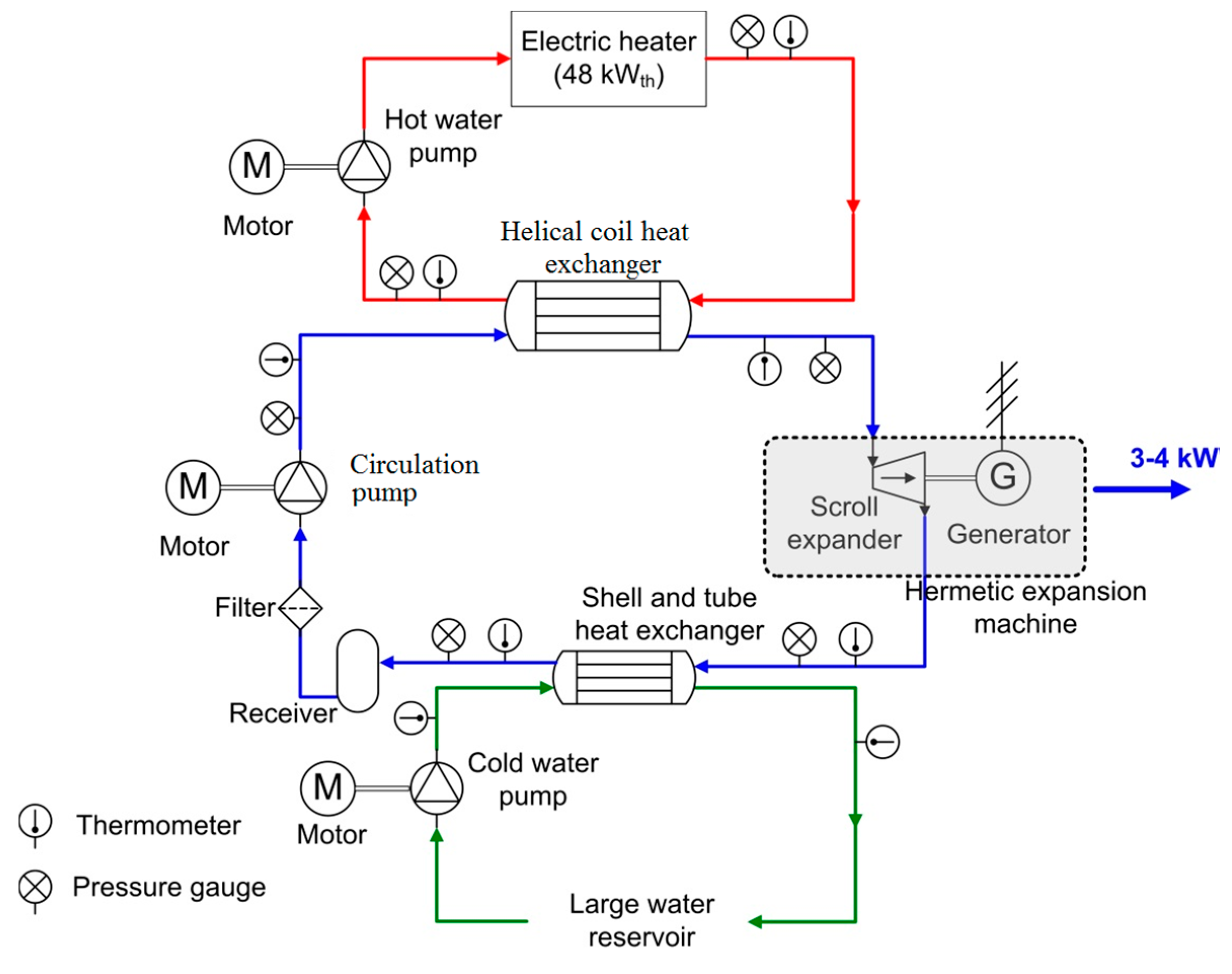
Under laboratory conditions, the maximum temperature of the heating fluid applied to the helical coil heat exchanger was 100 °C. This corresponds to the maximum temperature that can be achieved on-site with the solar collectors. The heating fluid (water) was heated by an electrical heater with a capacity of 48 kW
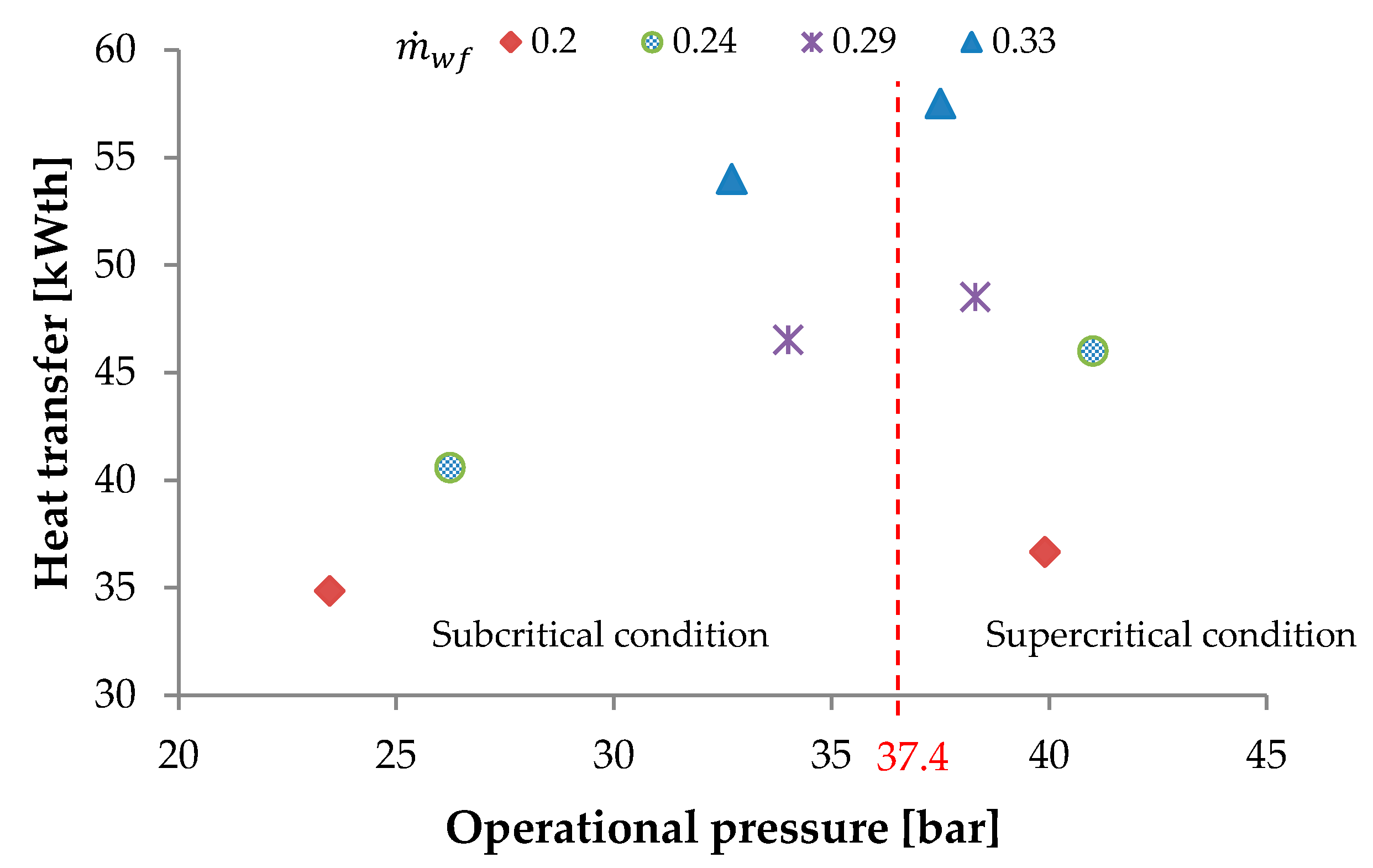
th. However, in this study the performance assessment of the heat exchanger was achieved at subcritical and supercritical operating conditions with the heating fluid temperature of 95 °C. The temperature measurements at the heating and working fluid side were performed with temperature sensors of type Pt100. In the installation there are in total eight temperature sensors with an accuracy of ±0.2 °C. Throughout the measurements, the pressure of the heating fluid was kept stable at 2.5 bar, while the pressure of the working fluid was in the range between 18 bar and 42 bar (subcritical and supercritical operating conditions, respectively). Six differential pressure transducers were used for the pressure measurements with an accuracy of 1% full scale pressure error (model 21Y, Keller, Winterthur, Switzerland). By measuring the pressures and the temperatures, the thermodynamic state of the working fluid and the water used for heating up or cooling down the system were calculated with an accuracy of 1.2% [17]. The positioning of all the sensors is indicated in Figure 2.
The mass flow rate of the organic fluid R-404A was determined at steady state conditions from the characteristic curve of the circulation (volumetric) pump. The volumetric flow rate shows a linear function with the rotational speed with a coefficient of 0.0205 (L/min)/rpm. This provides a reliable calculation of the flow rate with an estimated accuracy of 2% [2]. From the measured temperature and pressure of the organic fluid at the pump’s outlet and by using the software packages REFPROP [17]/EES [18] database for R-404A the mass flow rate was then calculated. The mass flow rate of the heating fluid was kept stable at 2.7 kg/s while the mass flow rate of the organic fluid was in the range of 0.20 kg/s up to 0.33 kg/s.
Furthermore, there is an uncertainty on the equations of state used to determine the thermophysical properties of the organic fluid R-404A (exclusively in the near-critical region). Pseudo-pure equations have been developed for calculating the thermodynamic properties of blends like R-404A. The uncertainty in the composition of the organic fluid depends from the manufacturer and is in the following order for the three other organic fluids (44 ± 2% R-125; 52 ± 1% R-143; 4 ± 2% R-134a) [19]. However, these equations are suitable for calculating the single-phase thermodynamic properties of blends. The dew and bubble point properties are calculated with the aid of additional equations for the saturation pressures. Estimated uncertainties between the calculations from the pseudo-pure fluid equations and the full mixture model are on average 0.01%. These equations are valid for the temperature range between 200 K and 450 K and can be extrapolated to higher temperatures. The accuracy of the density is 0.1%, but the critical region is excluded. There are differences of 0.1% up to 0.5% when taking the speed of sound and the heat capacity into consideration [20].
After defining the absolute errors of all sensors, by employing the Equation (1) it can be determined how these uncertainties propagate through the data reduction.
δ q = ( q x 1 · δ x 1 ) 2 + + ( q x i · δ x i ) 2
This equation shows the absolute error of q that depends on the parameters xi that has the independent and random absolute errors δ x i [21]. The relative measurement error of each parameter (mean value) is listed in Table 3.

3.2. Heat Transfer Coefficient

Experimental evaluation of the helical coil heat exchanger at elevated pressures (subcritical and supercritical state) of the working fluid was done by processing the measured data from the experiments like the temperatures, pressures, mass flow rates, etc. All sets of measurements were conducted at steady state condition by keeping the inlet parameters of the heating and working fluid stable. The performance evaluation of the heat exchanger is done as a “black box”, taking into account the temperature and pressure measurements at the inlet and the outlet of both sides of the heat exchanger. Furthermore, this data is used to deduce the overall heat transfer coefficient corresponding to the lumped parameter model.
Hence, the experimental results are analysed in a systematic way. The heat transfer rate is calculated from the temperature and enthalpy changes at the inlet and at the outlet of the heating fluid and the working fluid side of the heat exchanger with the following equations:
Q ˙ h f = m ˙ h f · c p ( T h f _ i n T h f _ o u t )
Q ˙ w f = m ˙ w f ( h w f _ o u t h w f _ i n )
where Q ˙ is the heat transfer rate, m ˙ h f , and m ˙ w f are the mass flow rates of the heating and working fluid, and h w f _ i n and h w f _ o u t are the enthalpy changes of the working fluid at the inlet and at the outlet of the heat exchanger, respectively. T h f _ i n and T h f _ o u t are the temperatures changes of the heating fluid at the inlet and at the outlet of the heat exchanger. The c p is the specific heat capacity of the heating fluid. Hence, the energy balance is examined by comparing the heat transfer rate at the heating fluid Q ˙ h f and working fluid Q ˙ w f side. For both operational conditions the heat balance highest deviation is 20% and it depends on the mass flow rate of the working fluid. The maximal deviation is reached at a mass flow rate of 0.33 kg/s. However, the relative error of the heat transfer rate at the working fluid side is in the range of 1.5–3.5%. The heat loss to the environment is calculated and is ~800 W. The deviation in the heat balance thus follows the uncertainty on the hot stream.
Furthermore, in order to determine the Nusselt number of the working fluid from the measurements the following steps for subcritical and supercritical operational conditions were applied. The overall thermal resistance R o v is expressed with Equation (4). It represents a sum of the thermal resistances corresponding to outer convection R o , the tube wall R w and the internal convection R i resistances, while the internal R f o , i and outer R f o , o fouling resistances are neglected (due to the new installation).
R o v = R o + R w + R i + R f o , i +   R f o , o      
By employing the proper expressions, Equation (4) can be rewritten as Equation (5).
1 U A   = 1 h t c o A o +   ln ( d o / d i ) 2 π κ L c   +   1 h t c i A i      
where the left side of the equation expresses the overall heat transfer resistance as a function of the overall heat transfer coefficient U and the surface area A . For calculating the overall heat transfer coefficient the outer surface area of the coil tube is taken into account ( A o ) . While on the right side of the equation h t c o and h t c i are the outer and internal convection heat transfer coefficients, respectively, d i and d o are the inner and outer tube diameters, κ is the wall thermal conductivity of the tube, L c is the coil tube length and A i is the inner tube surface area. With this equation the convection heat transfer coefficient at the working fluid side h t c i is computed.
Additionally, the overall heat transfer coefficient can be determined from the experiments by employing Equation (6):
U = Q ˙ w f A o · L M T D
where LMTD is the log mean temperature difference calculated with Equation (7) taking into consideration the counter-current flow in the heat exchanger.
L M T D = ( T h f _ i n T w f _ o u t ) · ( T h f _ o u t T w f _ i n ) l n ( T h f _ i n T w f _ o u t T h f _ o u t T w f _ i n )
The temperature change of the working fluid at the inlet and at the outlet of the heat exchanger is presented with the following abbreviations T w f _ i n and T w f _ o u t .
The LMTD method is based on constant fluid properties which is not the case in this work. Therefore, in order to account for these property changes of the working fluid, in both analyses (subcritical and supercritical operating conditions) the LMTD method was used by discretizing the length of the coil in a number of sections (control volumes).
In the supercritical operating conditions, the model was discretized in 20 control volumes where the overall enthalpy change h is divided in equal differences. The heat transferred in each control volume is equal because the enthalpy h and the mass flow rate of the working fluid m ˙ w f are considered as constants.
Furthermore, in the subcritical operating conditions the model is discretized in 100 control volumes for having higher stepwise accuracy in observing the phase changes along the coil tube length, by keeping the same methodology as in the aforementioned supercritical case.
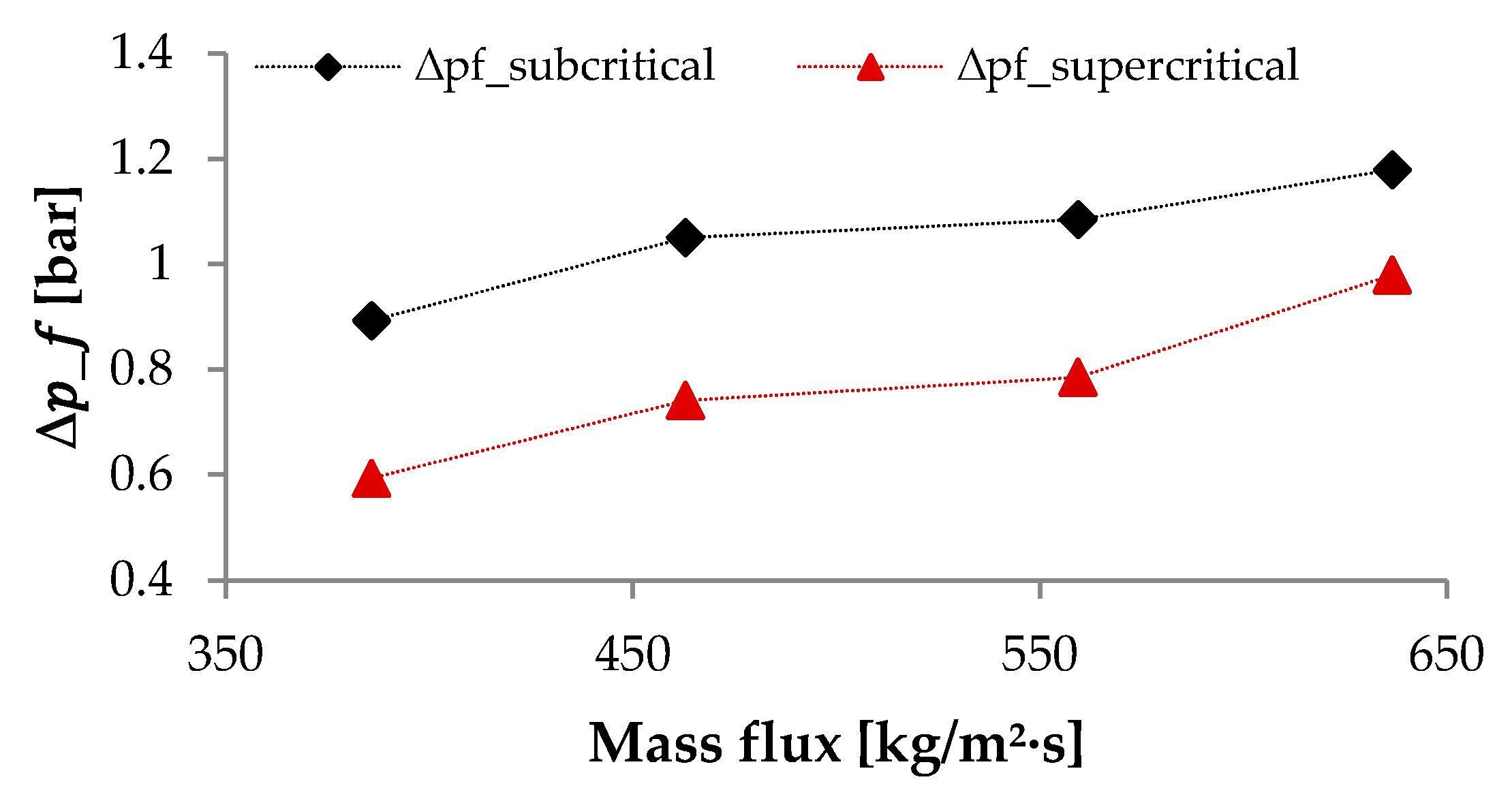
The heat flux from the measurements is determined by the Equation (8).
q = Q ˙ w f A o
The calculated heat flux from the measurements is in the range of 5 kW/m2–9 kW/m2 which is significantly lower than the critical heat flux [22,23]. At high (critical) heat fluxes deteriorated heat transfer occurs, which is not likely to arise in these testing conditions.
The bulk working fluid temperature T b _ w f and the coil tube wall temperature T w are computed by employing the Equations (9) and (10):
T b _ w f = T w f _ i n + T w f _ o u t 2        
T w = T b _ w f + T b _ h f 2        
where the bulk temperature of the heating fluid T b _ h f is determined by the Equation (11)
T b _ h f = T h f _ i n + T h f _ o u t 2        
The convection heat transfer coefficient h t c o at the heating fluid side can be determined with a heat transfer correlation deduced by Kern [24] which is derived for fully developed turbulent flow and is presented with Equation (12):
N u = 0.36 R e 0.55 P r 0.33 ( μ b μ w ) 0.14    
where Re is the Reynolds number, Pr is the Prandtl number and μ b and μ w are the viscosities of the heating fluid at the bulk and wall temperatures. After determining the values of the parameters mentioned in the text above, the experimental Nusselt number at the working fluid side can be calculated with the following Equation (13):
N u = h t c i · d h y d _ w f λ b _ w f  
where d h y d _ w f is the hydraulic diameter of the working fluid which in this case is the inner tube diameter d i and λ b _ w f is the thermal conductivity of the working fluid at bulk temperatures. Equation (13) is used for determining the experimental Nusselt number at supercritical operating conditions.
Moreover, for calculating the two-phase Nusselt number N u T P Equation (13’) is used where h t c T P is the two-phase convective heat transfer coefficient and the thermal conductivity λ l _ w f of the liquid phase of the working fluid is used as a scaling parameter rather than a combination of the two phases, liquid and gas phase conductivity.
N u T P = h t c T P · d h y d _ w f λ l _ w f  
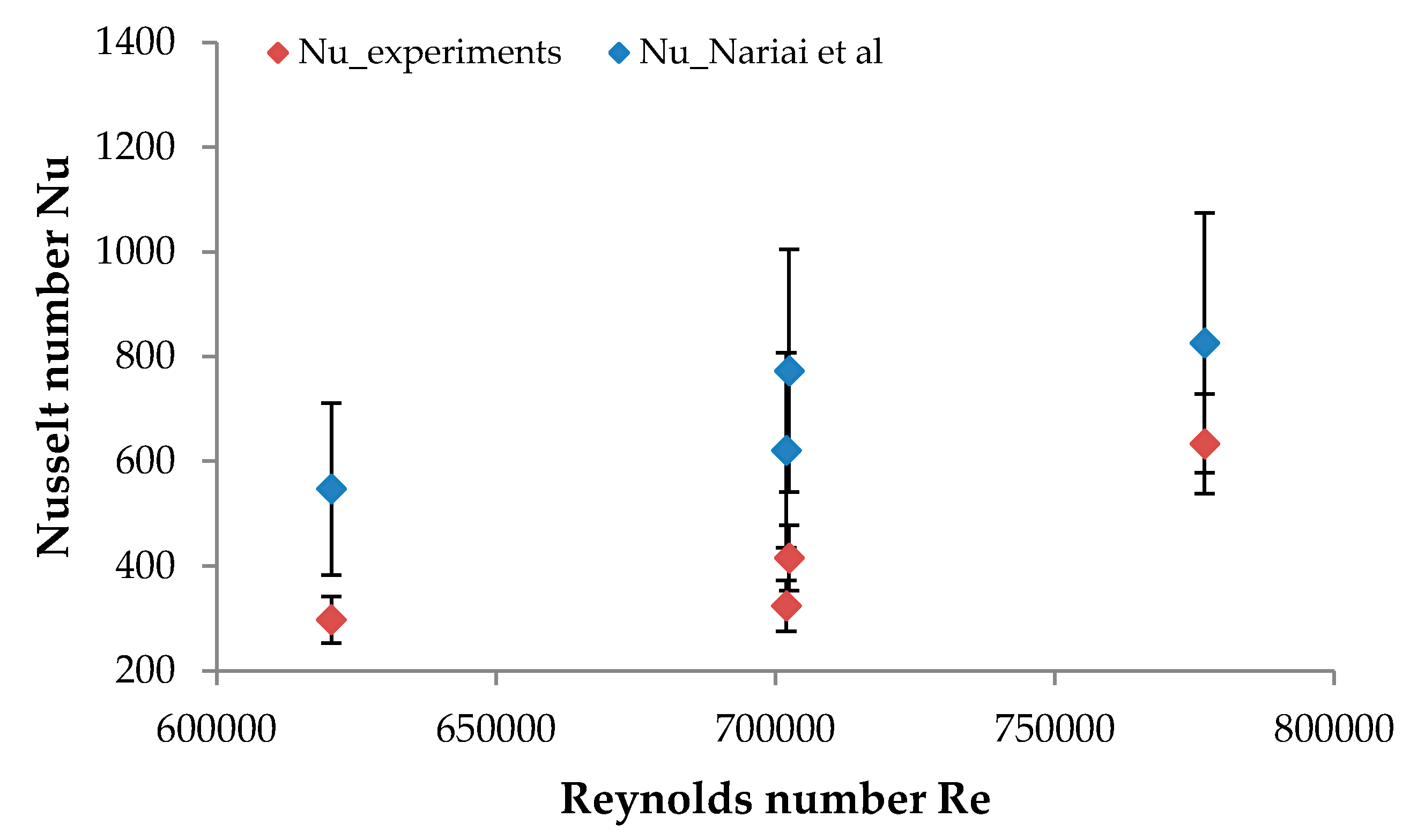
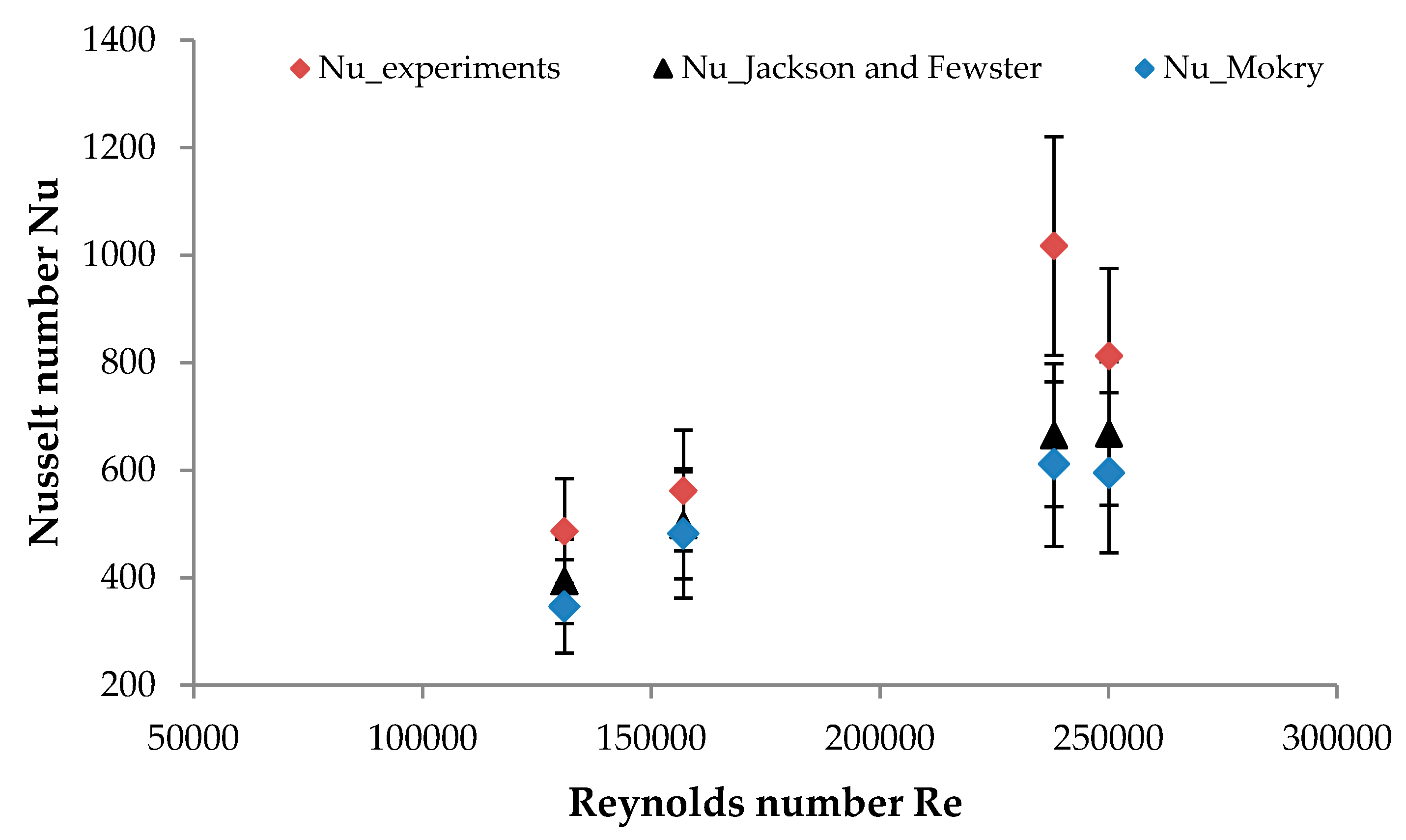
Furthermore, the predicted average Nusselt numbers for the subcritical case are calculated by means of reverse calculation using the Equations (5) and (6). Particularly, the overall heat transfer coefficient from Equation (6) is used to reversely calculate the lumped h t c i in the Equation (5).

3.3. Frictional Pressure Drop

The experimental pressure drop p e x p in the heat exchanger for both operating conditions was determined by two absolute pressure sensors. This includes the pressure drop occurring in the adiabatic part at the inlet and at the outlet of the heat exchanger p a d , the frictional pressure drop occurring in the heat exchanger p f and a pressure drop arising due to the acceleration of the working fluid p a .
p e x p = p a d + p f + p a
The pressure drop in the adiabatic part is a sum of the adiabatic sections at the inlet and at the outlet of the heat exchanger and are calculated with Equations (15) and (16):
p a d _ i n = f i n G w f 2 2 · ρ i n L a d _ i n d a d _ i n
p a d _ o u t = f o u t G w f 2 2 · ρ o u t L a d _ o u t d a d _ o u t
where Lad is the length of the adiabatic section, dad is the tube diameter, ρ is the density of the fluid in the adiabatic part, G w f is the mass flux of the fluid and f is the friction factor. This factor accounts for the energy loss due to the friction between the tube walls and the working fluid. Finolenko [25] derived the following correlation that can be used for determining the friction factor at the inlet and outlet of the helical coil heat exchanger under turbulent flow conditions as a function of the Reynolds (Re) number that is calculated based on the average property values of the working fluid:
f i n / o u t = [ 1.82 l o g R e i n / o u t 1.64 ] 2
Further, the acceleration pressure drop during the heating occurs due to the fluid’s density variations along the test section.
p a = G w f 2 ( 1 ρ o u t 1 ρ i n )
Hence, the frictional pressure drop along the heat exchanger for both operating conditions is calculated with Equation (19):
p f = p e x p p a d p a

4. Experimental Results and Discussion

4.1. Evaluation of the Heat Transferred in the Heat Exchanger at Subcritical and Supercritical Operating Conditions with a Heating Fluid Temperature of 95 °C

Evaluation of the heat transfer in the heat exchanger by taking into consideration the overall heat transfer coefficient at subcritical and supercritical operational condition was performed at constant inlet properties of the heating fluid. The inlet temperature of the water was at 95 °C, pressure at 2.5 bar and mass flow rate at 2.7 kg/s. Several sets of measurements were performed at various mass flow rates (0.20 kg/s–0.33 kg/s) of the working fluid. The inlet pressure of the organic fluid R-404A was in the range of 18 bar up to 41 bar. At higher mass flow rates, the temperature of the working fluid at the inlet of the heat exchanger rises as well. Figure 4 presents the heat transferred in kWth as a function of the mass flow rate of the working fluid in kg/s at both experimental environments. According to the results gained from the measurements, the heat transferred in the heat exchanger is ~10% higher at supercritical rather than subcritical conditions.
The nominal design value in terms of power is 41 kWth at a heating fluid inlet temperature of 95 °C and a mass flow rate of the working (organic) fluid of 0.25 kg/s. At these inlet conditions of the heating and the working fluid a heat transfer of 43 kWth at subcritical and 48 kWth at supercritical state were achieved. This yields to a better performance in terms of the heat transferred of ~5% and ~15% at subcritical and supercritical operating conditions, respectively.

4.2. Effects of the Operational Pressure to the Heat Transferred in the Heat Exchanger

There are several parameters that have influence on the operational pressure in the installation. The variation of the operational pressure is a function of the mass flow rate because these parameters follow the characteristic curves of the circulation (diaphragm) pump and the expander, as well as the pressure losses in all components (valves, fitting, tubes). During the measurements, by increasing the speed of the volumetric expander the operational pressure lowered and the mass flow rate increased. However, at subcritical operating conditions, a lot of measurements were conducted and variation of the speed of the circulation pump and the expander was possible. While supercritical conditions were very difficult to reach the investigation was possible at higher rotation (shaft) speed of the pump and low expander speed.
Figure 5 presents the heat transfer rate measured at different system pressures. Four different comparisons conducted at constant mass flow rate for both operating conditions are presented in the figure. The experiments were done at a mass flow rate of 0.20 kg/s, 0.24 kg/s, 0.29 kg/s and 0.33 kg/s at subcritical and supercritical pressures. From the comparison it can be concluded that at equivalent mass flow rates, a higher heat transfer rate in the heat exchanger is achieved when the pressure is higher (supercritical pressures).
However, it has to be emphasized that at lower system pressure of 34 bar (subcritical pressure) and mass flow rate of 0.3 kg/s a higher heat transfer rate is achieved in comparison to the three other measurements conducted at supercritical pressures (38.3 bar, 40 bar and 41 bar) but lower mass flow rates. The mass flow rate of the working fluid R-404A has a significant influence on the heat transfer rate in the heat exchanger. This means the pressure of the working fluid does not need to be so high. On the other hand, a higher mass flow rate requires higher pumping power and there is a larger pressure drop in the heat exchanger which has a negative influence on the ORC cycle efficiency. Therefore, for improving the efficiency of the ORC as a system all components need to be studied simultaneously. However, the aim of this work is to evaluate the performance of the heat exchanger and not the ORC cycle efficiency. Furthermore, the best performance is reached near the critical region when the pressure of the working fluid R-404A is ~5% higher than the critical pressure.

4.3. Influence of the Frictional Pressure Drop in the Heat Exchanger

Increasing the mass flow rate of the working fluid resulted in a higher pressure drop over the helical coiled tube. For both working conditions (subcritical and supercritical) the measured pressure drop in the heat exchanger was between 0.6 bar and 1.2 bar and this value depends on the operating conditions. The calculated frictional pressure drops for various mass fluxes for subcritical and supercritical operating conditions is presented in Figure 6.
By increasing the mass flux, the frictional pressure drop p f increases significantly, which is apparent from Figure 6 and is valid for both operating conditions. The increase of the frictional pressure drop is influenced by the thermophysical property variations of the working fluid. At higher mass fluxes the bulk temperature of the working fluid R-404A and the wall temperature of the coil are raised as well, which results in the variations of the fluid’s property along the coil tube. According to the results from the measurements there is a temperature difference between the wall of the coil tube and the bulk temperature of the fluid of ~20 °C. Because the wall temperature is much higher than the bulk fluid temperature the density of the fluid near the wall decreases while the fluid velocity near the wall increases in order to maintain flow continuity which intensifies the mixing of the fluid near the wall. Hence, the friction between the wall and the working fluid rises.

4.4. Comparison of the Experimental Nusselt Number with Heat Transfer Correlations from Literature

The results from the measurements are compared with heat transfer correlations from the literature [26,27,28,29] for both operating conditions. Only the heat transfer correlation derived by Nariai et al. [26] is applicable for helical coil tubes in the operational range of 20 bar < p < 35 bar, 150 kg/m²∙s < G < 850 kg/m²∙s. The heat transfer correlation derived by Seider–Tate [27] is valid for a single-phase turbulent flow Re ≥ 10,000. Besides, the heat transfer correlation derived by Nariai et al. [26] the other three correlations are developed for straight tubes positioned either horizontally or vertically. In order to account for the helical coil design that has an influence on the heat transfer, the three heat transfer (Nusselt) correlations were multiplied with the factor derived by Schmidt [30] ζ = 1 + 3.6 [ 1 d i D c ] ( d i D c ) 0.8 . This correction factor accounts for the curvature effect and the secondary flow that occurs in the helical coil tube. There is a confidence in applying this safety coefficient because the Reynolds number and the ratio Dc/di are in the recommended range (20,000 < Re < 150,000 and 5 < Dc/di < 84).
The selected heat transfer correlations are presented in Table 4.
For analysing the results obtained at subcritical state two different heat transfer correlations and [26,27] were implemented in a MATLAB model [31] (MATLAB 8.0 and Statistics Toolbox 8.1, The MathWorks, Inc., Natick, MA, USA). Hence, for the single-phase liquid (preheating section) and the vapour (superheated section) state respectively, the heat transfer correlation from Seider–Tate [27] was used. Since its accuracy is not reported, it is assumed as 20%. Furthermore, for the two-phase region a heat transfer correlation derived by Nariai et al. [26] was implemented. This heat transfer correlation has been derived for a helical coil tube and is applicable for the conditions from the measurements. It uses the Lockhart–Martinelli parameter Xtt to incorporate the effects of the two-phase flow and is defined as:
X t t = 1 x x ( ρ g ρ l ) 0.571 ( μ l μ g ) 0.143
where x is the vapour quality. The boiling number B o = q G h l g and the Reynolds number with the assumption of only liquid flow R e l o = d i ( 1 x ) G / μ l are used in the Nariai et al. [26] correlation. According to the data in the work of Nariai et al. [26] this heat transfer correlation has a mean absolute error of 30%.
For determining the Nusselt numbers from the measurements the LMTD method was applied (Section 3.2). A comparison between the experimental Nusselt number N u = h t c · d λ and the Reynolds number R e = m ˙ w f A · μ with the heat transfer correlations from the literature is presented in Figure 7.
The uncertainty of the Nusselt number obtained from the experiments is in the range between 8% up to 15% which shows that not all of the measurement points fall within the uncertainty range of the heat transfer correlation from the literature. The error margins of the predicted and the experimental Nusselt numbers come closer as the Reynolds number increases. It is important to note that the application range of the Nariai et al. [26] correlation’s does not fully overlap with the experimental conditions of the present study. In particular, the heat flux is significantly out of the range. This becomes less dominant in the predictions if the mass flow rate (thus, Reynolds number) of the reversely calculated experimental cases gets higher. As can be seen from the first equation in the Table 4, when the working fluid mass flow rate (mass flux G) is high, the boiling number B o becomes smaller and the heat flux’s influence on the predicted Nusselt number decreases. In addition to that, the increasing Reynolds number makes the influence on the heat flux parameter less dominant. The combination of these two parameters leads to a better match between the experimental and the predicted Nusselt numbers.
Additionally, two heat transfer correlations of Dittues–Boelter type, derived by Jackson and Fewster [28] and Mokry et al. [29] for the supercritical fluids (water, CO2) are used for the comparison of the experimental Nusselt number obtained at supercritical heat transfer measurements. These two heat transfer correlations are developed for horizontal and vertical flow and are one of the most accurate heat transfer correlations derived for supercritical heat transfer fluids and have a wide application range. The heat transfer correlation derived by Mokry et al. [29] was used in the design procedure of the helical coil heat exchanger and is valid for 200 kg/m²∙s < G < 1500 kg/m²∙s. The results are presented in Figure 8.
The deviation of these heat transfer correlations is in the range of ±20 to ±25%. However, the uncertainties of the experimental Nusselt number obtained at supercritical conditions are in the range between 16% and 32%. From the obtained data it can be concluded that the uncertainty for most of the measurement points fall within the interval margin compared with both literature heat transfer correlations.

5. Conclusions

An experimental study was conducted to evaluate the performance of the helical coil heat exchanger at subcritical and supercritical operating state under solar ORC conditions.
From the measurements and the analysis, it can be concluded that in terms of heat transfer, better performance is achieved at supercritical conditions. By increasing the working fluid’s mass flow rate a significant change/increase in the heat transfer rate is present. However, by comparing the results from the measurements, at supercritical operating conditions in the heat exchanger the heat transfer rate is 10% higher. Furthermore, compared to the nominal designed value such as the mass flow rate of 0.25 kg/s of the working fluid and inlet temperature of the heating fluid of 95 °C, the heat exchanger outperforms at both operating conditions. Evaluating the effects of the operational pressure on the heat transferred in the heat exchanger leads to the conclusion that the supercritical pressure yields better results in terms of the heat transfer in the heat exchanger at the same mass flux.
Heat transfer (Nusselt) correlations from the literature were compared with the results from the experiments at subcritical and supercritical working environments. The measurement points do not show that the difference is (statistically) significant for either operating condition. However, due to the severe changes of the thermophysical properties of the working fluid near the critical region the uncertainty is higher when there is supercritical heat transfer in the heat exchanger.

Acknowledgments

The research leading to these results has received funding from the European Union’s 7th Framework Programme managed by the Research Executive Agency (REA), http://ec.europa.eu/research/rea ([FP7/2007–2013] [FP7/2007–2011]) under grant agreement n° 315049 (CPV/RANKINE), FP7-SME-2012. A part of the results presented in this paper has been obtained within the framework of the IWT SBO-110006 project The Next Generation Organic Rankine Cycles (www.orcnext.be), funded by the Institute for the Promotion and Innovation by Science and Technology in Flanders. This financial support is gratefully acknowledged. The Ghent University research (ATHT) team would also like to thank to the project (CPV/RANKINE) coordinator, the Agriculture University of Athens (George Papadakis; Dimitris Manolakos; George Kosmadakis) and all the other partners for their work within this project.

Author Contributions

Marija Lazova and Alihan Kaya analysed the experimental data; Marijn Billiet and Steven Lecompte contributed with the analysis tools; Dimitris Manolakos provided the experimental data; Marija Lazova wrote the paper. Michel De Paepe reviewed the final work.

Conflicts of Interest

The authors declare no conflict of interest.

Nomenclature

A total heat transfer area (m2)
c p specific heat capacity (J/kg K)
d tube diameter (m)
D shell diameter (m)
EESEngineering Equation Solver
G mass flux of the working fluid (kg/m2∙s)
H Height of the heat exchanger (m)
h t c heat transfer coefficient (W/m2K)
h enthalpy (kJ/kg)
IHEInternal heat exchanger
L coil (tube) length (m)
L M T D log mean temperature difference
m ˙ mass flow rate (kg/s)
N number of coil turns
ORCorganic Rankine cycle
p pressure (bar)
R convection resistance (°C/W)
T temperature (°C)
q heat flux (W/m2)
Q heat transfer rate (kWth)
u velocity of the working fluid (m/s)
U overall heat transfer coefficient (W/m2K)

Dimensionless Numbers

BoBoiling number
NuNusselt number
ReReynolds number
PrPrandtl number
XttLockhart-Martinelli parameter
ffriction factor

Fluids 3

CO2carbon dioxide
R-404AHFC blend (R-125/143a/134a)
R-1232,2-Dichloro-1,1,1-trifluoroethane
R-125Pentafluoroethane
R134aTetrafluoroethane
R-245faPentafluoropropane
R-32difluoromethane

Greek Letters

ζ Schmidt factor for curvature ratio (-)
difference
λ thermal conductivity of a fluid (W/mK)
κthermal conductivity of the material (W/mK)
µviscosity at bulk fluid temperature (kg/ms)
ρ density of the fluid at the inlet (kg/m3)

Subscripts

aacceleration
adadiabatic
bbulk
ccoil
expexperiment
ffrictional
fofouling factor
hfheating fluid
hydhydraulic
iinner
ininlet
lliquid
oouter
outoutlet
ovoverall
TPtwo phase
wwall
wfworking fluid

References

  1. Lecompte, S.; Huisseune, H.; van den Broek, M.; Vanslambrouck, B.; De Paepe, M. Review of organic Rankine cycle (ORC) architectures for waste heat recovery. Renew. Sustain. Energy Rev. 2015, 47, 448–461. [Google Scholar] [CrossRef]
  2. Kosmadakis, G.; Manolakos, D.; Papadakis, G. Experimental investigation of a low-temperature organic Rankine cycle (ORC) engine under variable heat input operating at both subcritical and supercritical conditions. Appl. Therm. Eng. 2016, 92, 1–7. [Google Scholar] [CrossRef]
  3. Lazova, M.; Huisseune, H.; Kaya, A.; Lecompte, S.; Kosmadakis, G.; De Paepe, M. Performance evaluation of a helical coil heat exchanger working under supercritical conditions in a solar organic Rankine cycle installation. Energies 2016, 9, 432. [Google Scholar] [CrossRef]
  4. Lecompte, S.; Lemmens, S.; Huisseune, H.; Van den Broek, M.; De Paepe, M. Multi-objective thermo-economic optimization strategy for ORCs applied to subcritical and transcritical cycles for waste heat recovery. Energies 2015, 8, 2714–2741. [Google Scholar] [CrossRef]
  5. Shengjun, Z.; Wang, H.; Guo, T. Performance comparison and parametric optimization of subcritical organic Rankine cycle (ORC) and transcritical power cycle system for low-temperature geothermal power generation. Appl. Energy 2011, 88, 2740–2754. [Google Scholar] [CrossRef]
  6. Quoilin, S.; Lemort, V.; Lebrun, J. Experimental study and modeling of an organic Rankine cycle using scroll expander. Appl. Energy 2010, 87, 1260–1268. [Google Scholar] [CrossRef]
  7. Hu, K.; Zhu, J.; Li, T.; Lu, X.; Zhang, W. Experimental investigation on characteristics of evaporator vaporization and pressure drops in an organic Rankine cycle. In Proceedings of the 7th International Conference on Applied Energy—ICAE2015, Abu Dhabi, UAE, 28–31 March 2015. [Google Scholar]
  8. Vetter, C.; Wiemer, H.-J.; Kuhn, D. Comparison of sub and supercritical organic Rankine cycles for power generation from low-temperature/low-enthalpy geothermal wells, considering specific net power output and efficiency. Appl. Therm. Eng. 2013, 51, 871–879. [Google Scholar] [CrossRef]
  9. Schröder, E.; Neumaier, K.; Nagel, F.; Vetter, C. Study on heat transfer in heat exchangers for a new supercritical organic Rankine cycle. Heat Trans. Eng. 2014, 35, 1505–1519. [Google Scholar] [CrossRef]
  10. Walraven, D.; Laenen, B.; D’haeseleer, W. Comparison of shell-and-tube with plate heat exchangers for the use in low-temperature organic Rankine cycles. Energy Environ. 2014, 87, 227–237. [Google Scholar] [CrossRef]
  11. Meyer, D.; Wong, C.; Engel, F.; Krumdieck, S. Design and build of a 1 kilowatt organic Rankine cycle power generator. In Proceedings of the 35th New Zealand Geothermal Workshop 2013, Rotorua, New Zealand, 18–20 November 2013. [Google Scholar]
  12. Zhu, Y.; Hu, Z.; Zhou, Y.; Jiang, L.; Yu, L. Discussion of the internal heat exchanger’s effect on the organic Rankine cycle. Appl. Therm. Eng. 2015, 75, 334–343. [Google Scholar] [CrossRef]
  13. Kaya, A.; Lazova, M.; Bağcı, Ö.; Lecompte, S.; Ameel, B.; De Paepe, M. Design sensitivity analysis of a plate-finned air-cooled condenser for low-temperature organic Rankine cycles. Heat Trans. Eng. 2016. [Google Scholar] [CrossRef]
  14. Lazova, M.; Daelman, S.; Kaya, A.; Huisseune, H.; De Paepe, M. Heat transfer in horizontal tubes at supercritical pressures for ORC application. In Proceedings of the 10th International Conference on Heat Transfer, Fluid Mechanics and Thermodynamics, Orlando, FL, USA, 14–16 July 2014. [Google Scholar]
  15. Kosmadakis, G.; Landelle, A.; Lazova, M.; Manolakos, D.; Kaya, A.; Huisseune, H.; Karavas, C.S.; Tauveron, N.; Revellin, R.; Haberschill, P.; et al. Experimental testing of a low-temperature organic Rankine cycle (ORC) engine coupled with concentrating PV/thermal collectors: Laboratory and field tests. Energy 2016, 117, 222–236. [Google Scholar] [CrossRef]
  16. Deconinck-Wanson. Available online: http://www.deconinck.be/en (accessed on 28 April 2017).
  17. Lemmon, E.W.; Huber, M.L.; Mc Linden, M.O. NIST Standard Reference Database 23: Reference Fluid Thermodynamic and Transport Properties—REFPROP; National Institute of Standards and Technology: Gaithersburg, MD, USA, 2007.
  18. Klein, S.A. Engineering Equation Solver (EES), F-Chart Software: Middleton, WI, USA, 2013.
  19. List of Refrigerants. Available online: https://en.wikipedia.org/wiki/List_of_refrigerants (accessed on 28 April 2017).
  20. Lemmon, E.W. Pseudo-pure fluid equations of state for the refrigerant blends R-410A, R-404A, R-507A, and R-407C. Int. J. Thermophys. 2003, 24, 991–1006. [Google Scholar] [CrossRef]
  21. Taylor, R.J. An Introduction to Error Analysis: The Study of Uncertainties in Physical Measurements; University Science Books: Sausalito, CA, USA, 1983. [Google Scholar]
  22. Styrikovich, M.A.; Margulova, T.K.; Miropol’skii, Z.L. Problem in the development of designs of supercritical boilers. Teploenergetika 1 1967, 14, 5–9. [Google Scholar]
  23. Pioro, I.L.; Khartabil, H.F.; Duffey, R.B. Heat transfer to supercritical fluids flowing in channels—Empirical correlations (survey). Nucl. Eng. Des. 2004, 230, 69–91. [Google Scholar] [CrossRef]
  24. Kern, D.Q. Process Heat Transfer 1950; McGraw-Hill: New York, NY, USA, 1950. [Google Scholar]
  25. Kakaç, S.; Liu, H.; Pramuanjaroenkij, A. Heat Exchangers, Selection, Rating, and Thermal Design; CRC Press: Boca Raton, FL, USA, 2012; pp. 117–118. [Google Scholar]
  26. Nariai, H.; Kobayashi, M.; Matsuoka, T. Friction pressure drop and heat transfer coefficient of two-phase flow in helically coiled tube once-through steam generator for integrated type marine water reactor. J. Nucl. Sci. Technol. 1982, 19, 936–947. [Google Scholar] [CrossRef]
  27. Incropera, F.D.; DeWitt, D.P. Fundamentals of Heat and Mass Transfer; John Wiley and Sons: New York, NY, USA, 1990. [Google Scholar]
  28. Pioro, I.L.; Duffey, R.B. Literature Survey of Heat Transfer and Hydraulic Reistance of Water, Carbon Dioxide, Helium and Other Fluids at Supercritical and Near-Criitcal Pressures. Available online: http://www.iaea.org/inis/collection/NCLCollectionStore/_Public/35/087/35087435.pdf (accessed on 7 March 2017).
  29. Mokry, S.; Pioro, I.; Farah, A.; King, K.; Gupta, S.; Peiman, W.; Kirillov, P. Development of supercritical water heat-transfer correlation for vertical bare tubes. Nucl. Eng. Des. 2011, 241, 1126–1136. [Google Scholar] [CrossRef]
  30. Schmidt, E.F. Warmeubergang und Druckverlust in Rohrschlangen. Zeitschrift fur Technische Chemie, Verfahrenstechnik und Apparatewesen 1967, 39, 781–832. [Google Scholar] [CrossRef]
  31. MATLAB 8.0 and Statistics Toolbox 8.1; The MathWorks, Inc.: Natick, MA, USA, 2016.
Figure 1. T-s diagram of subcritical and supercritical heat transfer in the heat exchanger in an organic Rankine cycle (ORC).
Energies 10 00619 g001
Figure 2. Layout of the experimental ORC test facility (laboratory installation) [2,3,15].
Energies 10 00619 g002
Figure 3. Heat exchanger: (a) a helical coil; (b) final assembly of the component; and (c) insulated and installed component in the installation in the laboratory [3].
Energies 10 00619 g003
Figure 4. Heat transfer on organic fluid side at different pressure and mass flow rates at 95 °C.
Energies 10 00619 g004
Figure 5. Effects of the system pressure on the heat transfer.
Energies 10 00619 g005
Figure 6. Frictional pressure drop p f for various mass fluxes at subcritical and supercritical conditions. p f : frictional pressure drop.
Energies 10 00619 g006
Figure 7. Comparison of the experimental Nu number with the heat transfer correlation from literature obtained at subcritical conditions.
Energies 10 00619 g007
Figure 8. Comparison of the experimental Nu number with the heat transfer correlation from literature obtained at supercritical conditions.
Energies 10 00619 g008
Table 1. Overview of the properties of R-404A. GWP: global warming potential.
PropertyUnitValue
R-125/R-143/R-134a--
44% C2HF5 52% C2H3F3·4% C2H2F4--
Tcrit°C71.2
pcritBar37.4
ODP0
GWP (100y)3260
Table 2. Summary of the final geometrical values of the helical coil heat exchanger.
ParameterUnitValue
Tube outer diameter, domm33.7
Tube inner diameter, diMm25.7
Tube thickness, tMm4
Inner shell diameter, DiM0.526
Outer shell diameter, DoM0.674
Coil diameter, DcM0.6
Coil pitch (turn’s distance), p0.042
Height of the heat exchanger, HcM1.508
Coil length, LcM66
Number of coil turns, Nc35
Total heat transfer area, Am26.984
Table 3. Accuracy of calculated parameters [2,3].
ParameterRangeRelative Error (%)
Heat input to ORC12–48 kWth2.62
Expander power production0.5–3 kWe2.62
Pressure ratio1.7–2.61.40
Expansion efficiency20–85%2.66
Thermal efficiency0–4.2%3.71
Volume flow rate1–30 L/min2.00
Table 4. Heat transfer correlations used for the comparison with the experimental Nusselt (Nu) number.
Author ReferenceCorrelationFluidFlowError
Subcritical conditions
Nariai et al. [26] N u = 170 R e l o 0.8 P r l 1 3 ( B o + 0.00015 X t t 0.67 ) Water Helical coil±30%
Seider–Tate [27] N u b = 0.023 R e b 0.8 P r ¯ 1 / 3 ( μ b μ w ) 0.14 -Horizontal±20%
Supercritical conditions
Jackson and Fewster [28] N u b = 0.0183 R e b 0.82 P r ¯ 0.5 ( ρ w ρ b ) 0.3 Water, CO2Horizontal±20%
Mokry et al. [29] N u b = 0.0061 R e b 0.904 P r ¯ b 0.684 ( ρ w ρ b ) 0.564 WaterVertical±25%

