3.1. Intermediate-Frequency Vacuum Arc Voltage
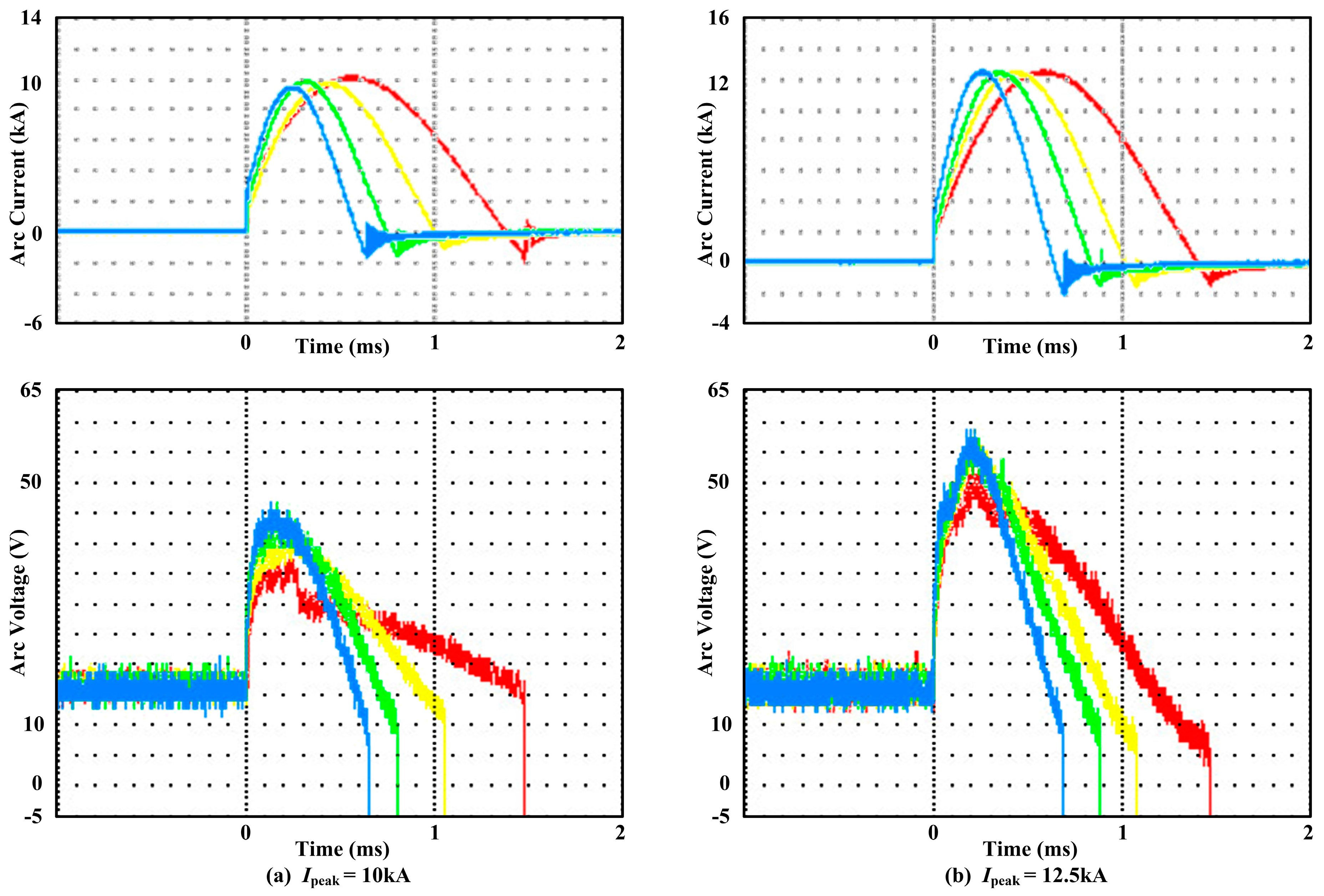
Figure 2 shows the vacuum arc current and voltage for different intermediate-frequencies and currents. According to the experiment data, it is found that an increase in vacuum arc voltage is related to frequency and current. Due to the thermal inertia of plasma, the ionization is inadequate. As a result, the arc resistivity should basically remain unchanged when the current is increasing, and in intermediate-frequency vacuum current, we have found that the arc path curves when the arc is burning at the lateral of contacts, which is equivalent to the length of arc column is lengthened. It can be seen that the arc resistance increases, which causes the rise of arc voltage [
15]. As shown in the figure, as the frequency increases, the peak value of the voltage increases and the time of the peak value occurs earlier. If we consider the beginning of the current as the zero time, when the current peak value is 10 kA, the voltage peak increases from 36 V at 360 Hz to 44 V at 850 Hz, and the time of appearance of the voltage peak is at 270.0 μs at 360 Hz compared to 137.6 μs at 850 Hz. When the current peak value was 12.5 kA, the voltage peak increased from 50 V at 360 Hz to 58.7 V at 780 Hz, and the time of appearance of the voltage peak was at 248.2 μs at 360 Hz compared to 199.6 μs at 780 Hz. The specific data is shown in
Table 1. The rise rate of the voltage d
u/d
t increases with the increase of frequency due to the increase in the voltage peak, and the time of the voltage peak appears earlier. After the peak, the voltage value decreases quickly and the rate is positively correlated to the frequency. There are no obvious differences before the voltage zero time.
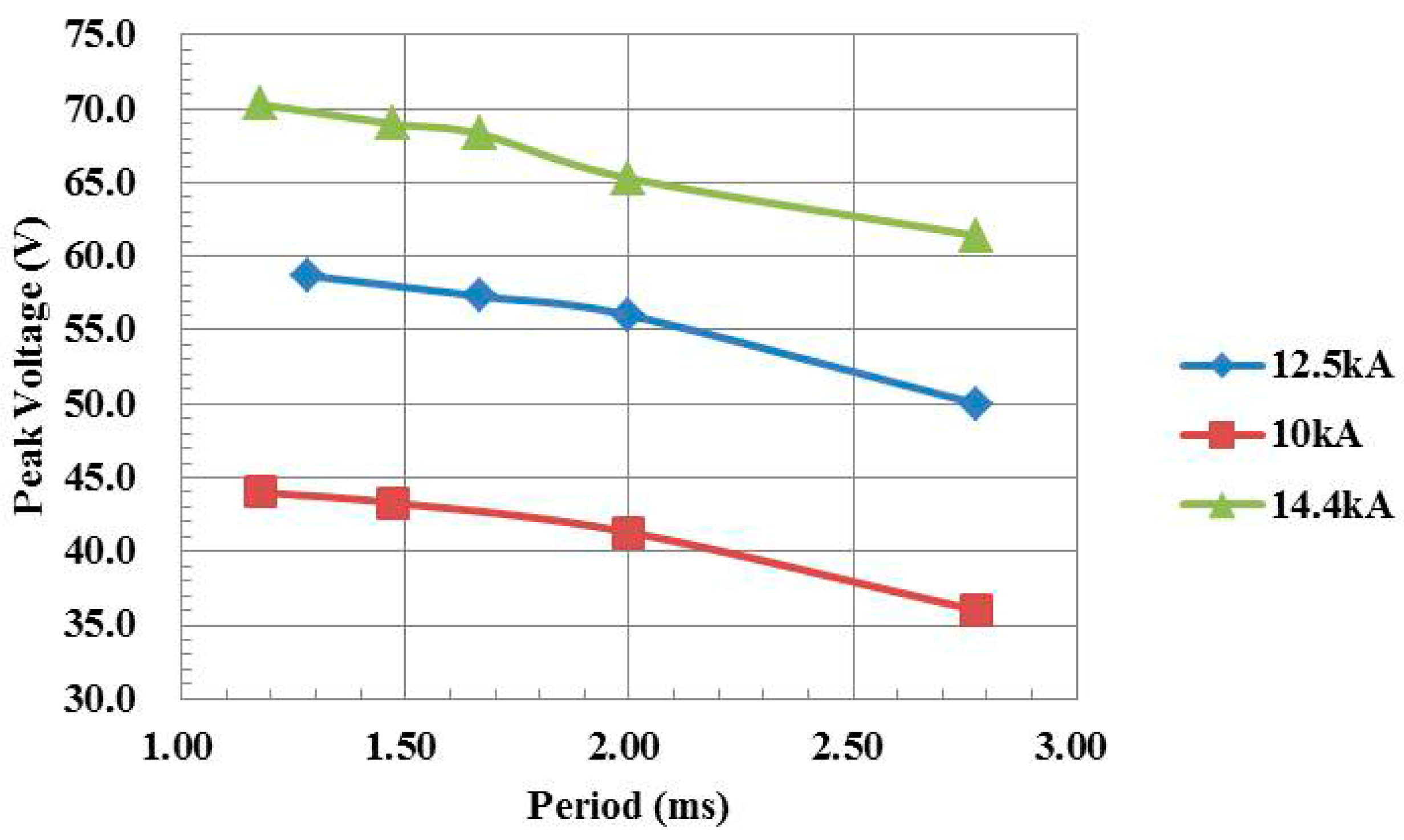
The curves of the arc voltage peak and intermediate-frequency current period are displayed in
Figure 3, which shows the current peak value of 10 kA, 12.5 kA, and 14.4 kA. As shown, for the same frequency, larger voltage peak values are related to larger current peak values, while with the same current peak, the voltage peak value gets larger if the frequency increases. At the same time, it can be seen that the relationship between voltage peak value and period is approximately linear. The gradients of the three curves are very similar.
If we consider the current frequency
f to be independent variables, and the voltage peak
Upeak to be a dependent variable, the following function can be obtained:
Based on the experimental data,
kf and
UI can be calculated by fitting, and the results are shown in
Table 2.
From these results,
kf is almost constant while
UI changes a lot. This can be explained as follows: in a linear relationship,
kf, which is the coefficient of
f, should be independent of
f. Only one vacuum circuit breaker is used in the experiment, so
kf must be related to the structural parameters, such as the gap distance and contact diameter.
UI shows the current effects on the arc voltage. According to power frequency research, the vacuum arc voltage increases as the current increases. Furthermore, a similar conclusion can be drawn in the 400 Hz experiment [
3].
After fitting
UI and
Ipeak, the following equation can be obtained:
The direct proportional relationship between
UI and
Ipeak is described in Equation (2), and the correlation coefficient is as high as 0.9975. However,
UI should be positive if
Ipeak is near zero. As a result, the equation must be modified:
In Equation (3),
kI is the coefficient of the current peak, and
UC is the voltage constant. In summary, the relationship between the voltage peak, current peak, and period can be expressed as follows:
According to Equation (4), it is shown that vacuum arc voltage is related to frequency and current. Regardless of whether the current or frequency increases, the current rise rate di/dt will also increase. On the one hand, more electrons will be injected into the arc in a unit time, so more ions will appear near the anode. As a result, the arc voltage will quickly rise to a certain level in the same amount of time, which will produce enough ions and create an electric field to attract the electrons. On the other hand, if the axial magnetic field lags at the start of the current, the vacuum will lack magnetic restrictions. Consequently, the ions can spread quickly outside the contact, which causes a shortage of ions near the anode. Thus, the arc voltage must increase to a certain level fast enough to sustain the plasma balance. In addition, the higher the frequency, the more serious the shortage is. Electrons are emitted from the cathode. Since the characteristics of the plasma are quasi-neutral, the distance between electrons and ions will not be greater than the Debye length. In the micro-area, the electrons turn around the ions at high speed and ions move slower than electrons. As a result, there is a greater impact on ions than electrons by a lack of magnetic restriction. In the two situations, the voltage peak and the rise rate of the voltage du/dt will increase.
3.2. Interruption Ability Related to the Frequency
The limit interruption current values for different frequencies are listed in
Table 3. As shown, the interruption ability decreases as the frequency increases.
The short interruption current is 50 kA/40 kA for the experimental BD010 vacuum breaker, for the conditions of 380 V/660 V at a power frequency of 50 Hz/60 Hz. However, according to these results, the interruption ability decreases significantly in the intermediate-frequency experiment. In the former power frequency vacuum arc investigation, Voshall [
18] believed that the current interruption ability was in inverse proportion to the frequency.
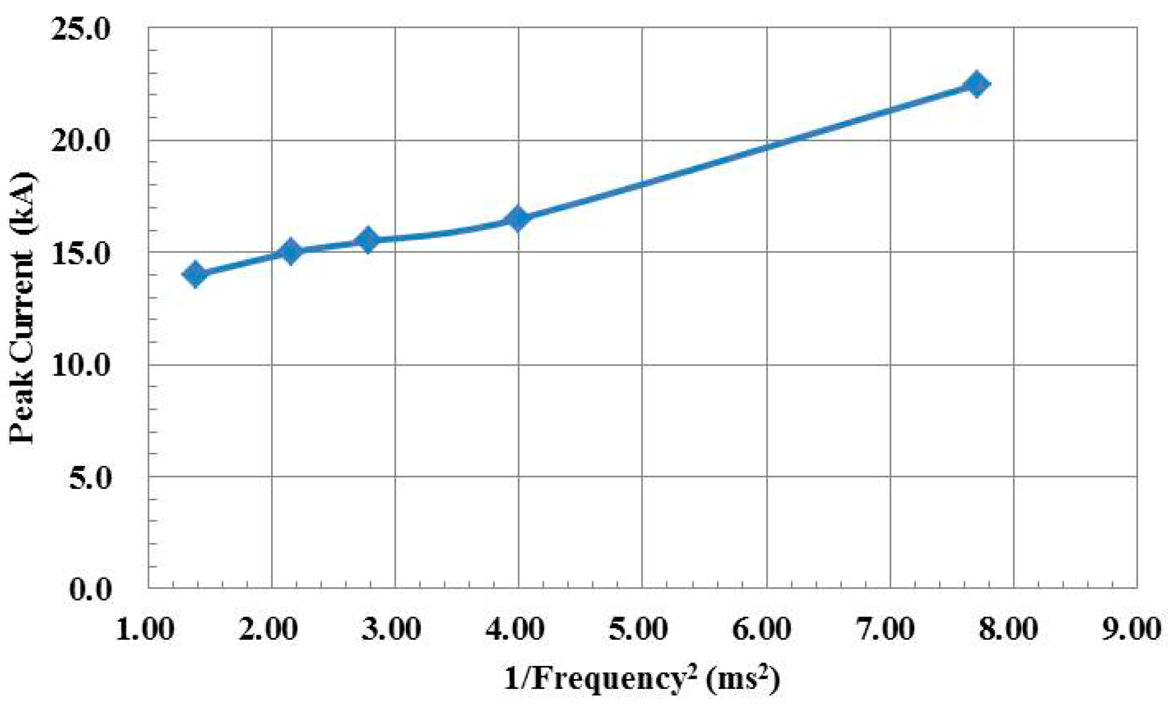
Based on the foregoing, the interruption of the AMF vacuum circuit breaker decreases as the current frequency increases. In the range of 360 Hz to 850 Hz, the relationship between the two variables can be simplified for convenience, as follows. If the square of the current is used as the horizontal ordinate and the limit current interruption peak as the vertical ordinate, an approximate linear curve can be drawn, as shown in
Figure 4.
Using the least squares method, the relational expression is:
where
a = 1.34 kA/ms
2 and
b = 11.86 kA. The main reason why the interruption limit decreases is that the rise rate of the voltage d
u/d
t increases as the frequency increases.
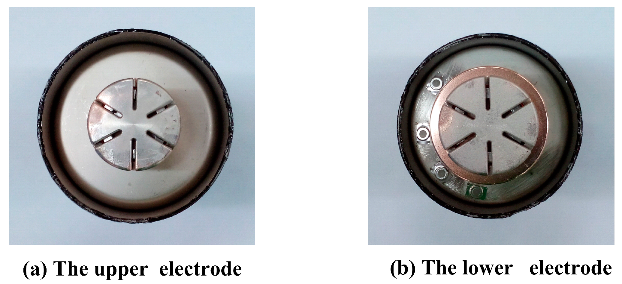
When compared to the same current in power frequency, the arc time of the intermediate-frequency is shorter and the injected arc energy is lower. Consequently, the erosion of the contacts is weaker. Thus, it can be inferred that the possibility of severe anode activity is lower, which can be proven by the erosions of the electrodes, which reflects the thermal state of the electrodes, as shown in the CuCr50 electrode surface photos in
Figure 5. Among which, in a successful interruption case, the upper contact is the anode and the lower contact is the cathode. While in the failed interruption case, the current is inverted after reignition, and the upper contact becomes the new cathode and the lower contact becomes the new anode. As a whole, the upper electrode operates longer as the anode. Compared to similar currents and contact materials in power frequency experiments [
13], there are uniform and shallow melted marks on the electrode surface after intermediate-frequency experiments through macroscopic observation, and the erosion on the anode is clearer than on the cathode. However, serious erosions with large squares cannot be observed. From this, we can conclude that there are no obvious active anode spots or intense arc modes.
3.3. Droplet Emission and Arc Reignition
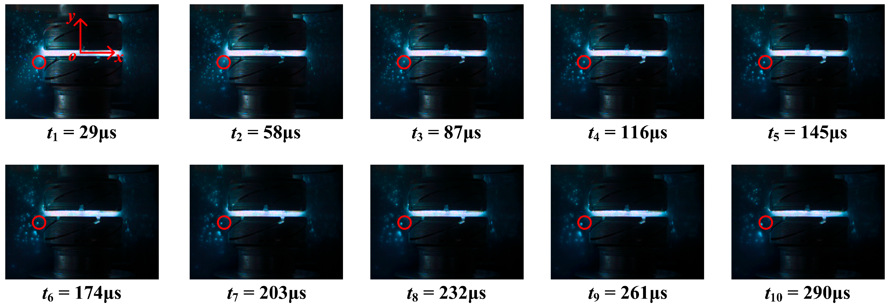
When the interruption fails, there will be a process from arc extinction to arc reignition. Pictures in the second half are displayed in detail in
Figure 6, with a current peak of 22.5 kA and a frequency of 360 Hz. In these photos, the upper contact is new cathode and the lower contact is new anode.
The droplets that are emitted from anode and cathode can be clearly seen. After arc extinction, the temperature is high, meanwhile the density of the residual plasmas and metal vapors are large inside the interrupter [
19]. So, when new energy is injected after reignition, more and larger metal droplets will be emitted. Droplet emission from vacuum arc is well known and is due to the high pressure in arc spots. Mesyats [
16] discussed the dynamics of molten metal during crater formation in the cathode spot of vacuum arc discharge and illustrated that the pressure of the cathode spot plasma causes the extrusion of molten metal from the hemispherical depression. However, in this paper, we are concerned with the movement process of droplet and arc column pressure, and even if droplets are not charged, it can be a source of metal vapors and plasmas that account for field emission and vacuum gap breakdown.
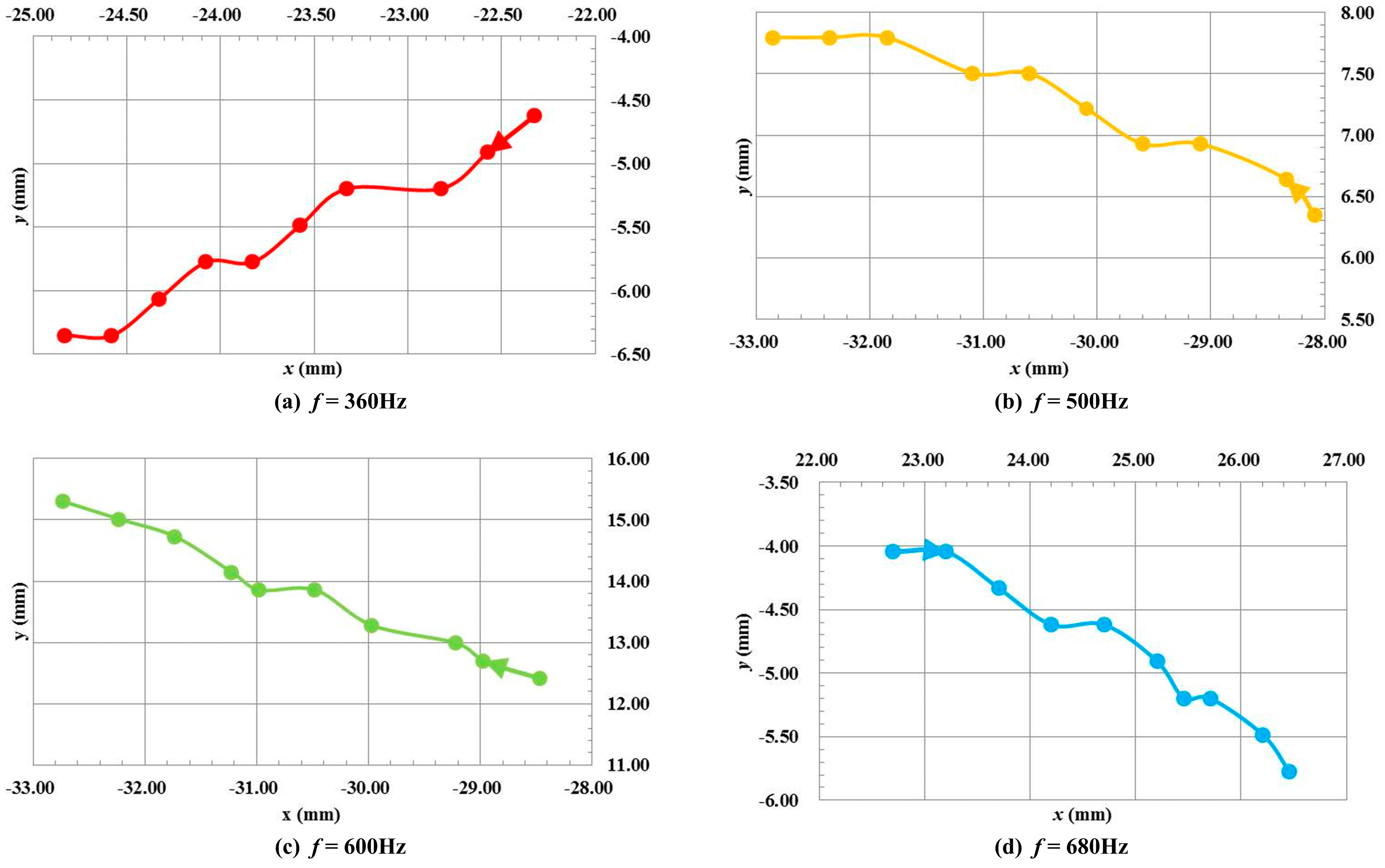
According to the xoy coordinate system, the selected measuring point A was marked with a red circle in
Figure 6. In the reignition process at 500 Hz, 600 Hz and 680 Hz, the same coordinate system and selected measuring points were used in each process. Considering the electrode diameter of 41 mm as the reference object, the coordinates of every time are recorded. Then, the moving trace of droplets can be observed, as shown in
Figure 7, in which the arrow shows the direction of movement.
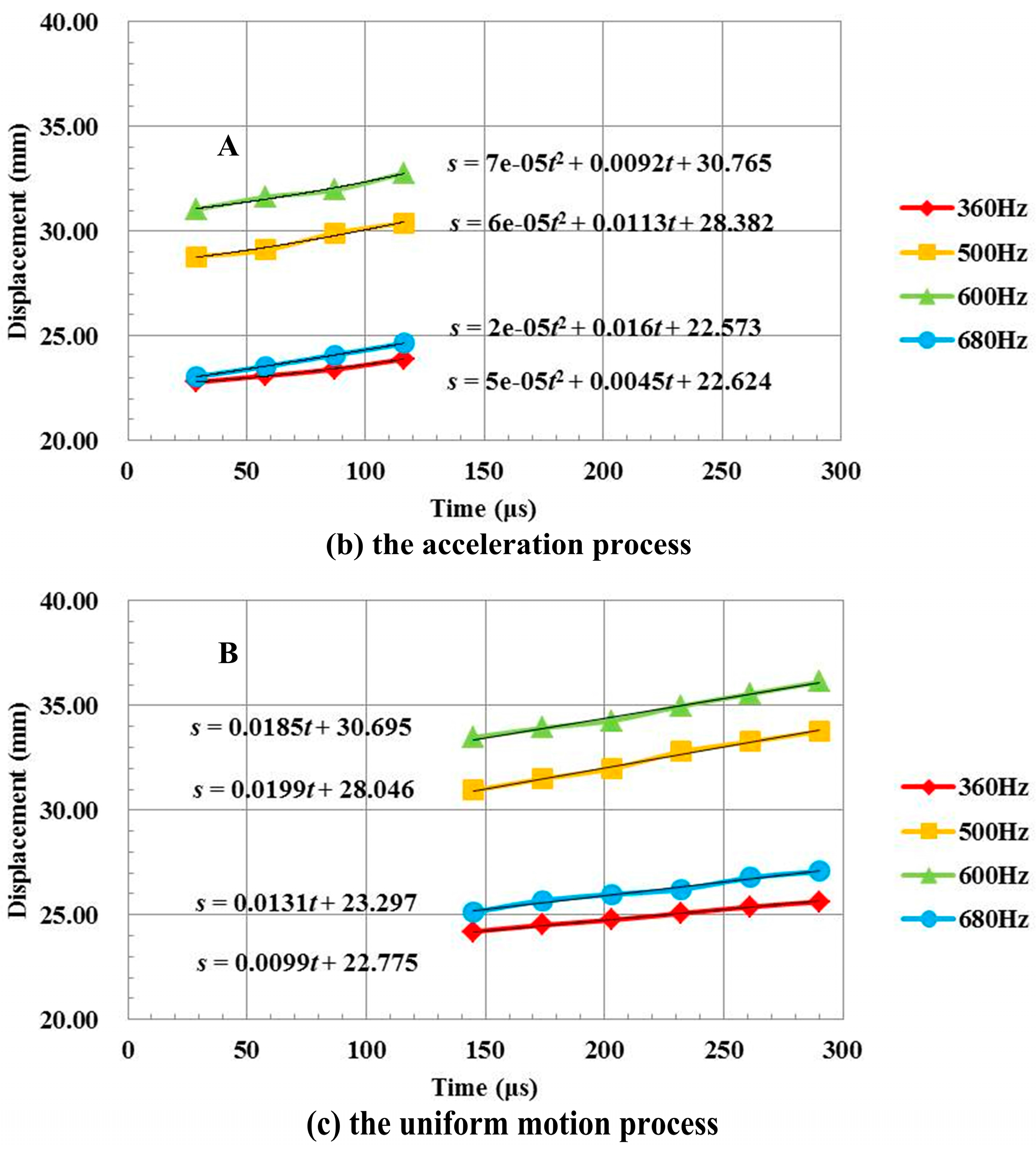
Based on the moving trace in two dimensions, the movement is not very affected by the frequency. After being emitted from the contact, the droplet moves toward the shield with an almost constant emitting β, which refers to the horizontal direction and can be calculated from the coordinates. The displacement–time curves for each droplet are shown in
Figure 8a. It can be seen that there is an acceleration process A and an even speed process B, as indicated by the dotted line in every curve. The acceleration process A is expressed in
Figure 8b and the uniform motion process B in
Figure 8c, and the equations for displacement–time of the movement are obtained using quadratic fitting and linear fitting methods.
The above process can be explained as follows: there are electrons, ions, metal vapor, and droplets in the arc area, so the pressure in the center is larger than that near the shield, which can cause the droplets to accelerate [
19]. In the former stage, the droplets start to leave the contacts and the arc gap where there is a large pressure, so it is an accelerating process. Then, in the later stages, the droplets have already left the gap where the pressure is small. Thus, it can be considered to be a uniform motion process. Based on the data, both the acceleration
a in the accelerating process and the average velocity
vavg in the entire process can be obtained, as listed in
Table 4.
Due to the calculation results, the order of magnitude for the acceleration is up to 10
4 m/s
2, so the droplets must be influenced by an outside force. If we consider the emitted metal droplets to be spherules and refer to the motion direction as β, we can establish the pressure
P as shown in
Figure 9a.
Considering the radius of the metal droplet as
r, a spherule coordinate system is established inside the droplet and the direction of pressure is referred to as +
w. As shown in
Figure 9, the force d
F on the ds is:
The cell area ds in the spherule coordinate system is:
If the particulate is too small, the pressure gradient in the
w direction can be considered constant in [−
r,
r]. If the outside force is taken into account, the pressure is
P0 where
w = 0, and the pressure
P at any angle can be expressed as:
By substituting Equations (7) and (8) into Equation (6), the following equation is obtained:
The force of the whole spherule can be obtained by integration:
Referring to Newton’s second law without gravity, the outside force of the droplet is:
where ρ is the density of the metal droplet.
By analyzing the deposited metal inside the glass shield using a scanning electron microscope (SEM), the components shown in
Table 5 were observed.
C and O are supposed to be foreign substance for less content. According to the data shown in
Table 5 and the density of Cu and Cr, the density of the emitted alloy was calculated to be approximately ρ ≈ 7.9 × 10
3 kg/m
3.
If the acceleration
a is 10
4 m/s
2, then the pressure gradient can be obtained based on the above results:
If the pressure gradient is considered to be constant along the direction of the metal droplet, and the acceleration distance
la is 1.5 mm in the experimental interrupter shown in
Figure 6–
Figure 8, then the pressure from the contact edge to the shield is:
In reality, there are inaccuracies in the above calculation because the pressure gradient is not constant everywhere. However, from the order of magnitude in the result, in the vacuum chamber, there is a large pressure from the center of the contact to the edge, which causes the electrons, ions, and metal droplets to accelerate and spread. At high current levels, if the density of the plasmas and metal vapors, and the number of metal droplets reaches a certain level, the arc may break down, which will cause the interruption to fail.
On the other hand, the half wave time of current at 360 Hz is 1.4 ms. The shortest distance
l from the contact to the shield is 30 mm in the experimental interrupter. Based on an overall consideration of the former study and
Table 4, we can make the following hypothesis: the emitting angle of the metal droplet β is 20°, and the average velocity
vavg is 15 m/s. The moving time t from the contact to the glass shield can be calculated by Equation (14):
That is, at current zero, the droplet will disappear after a period which is approximately equal to the half wave time of the intermediate-frequency current. Based on this, the metal droplets and particles are the source of the plasma in the space after the arc is extinguished, which may cause the arc to reignite.


