
Thermal Analysis of a Thermal Energy Storage Unit to Enhance a Workshop Heating System Driven by Industrial Residual Water


Abstract
:1. Introduction
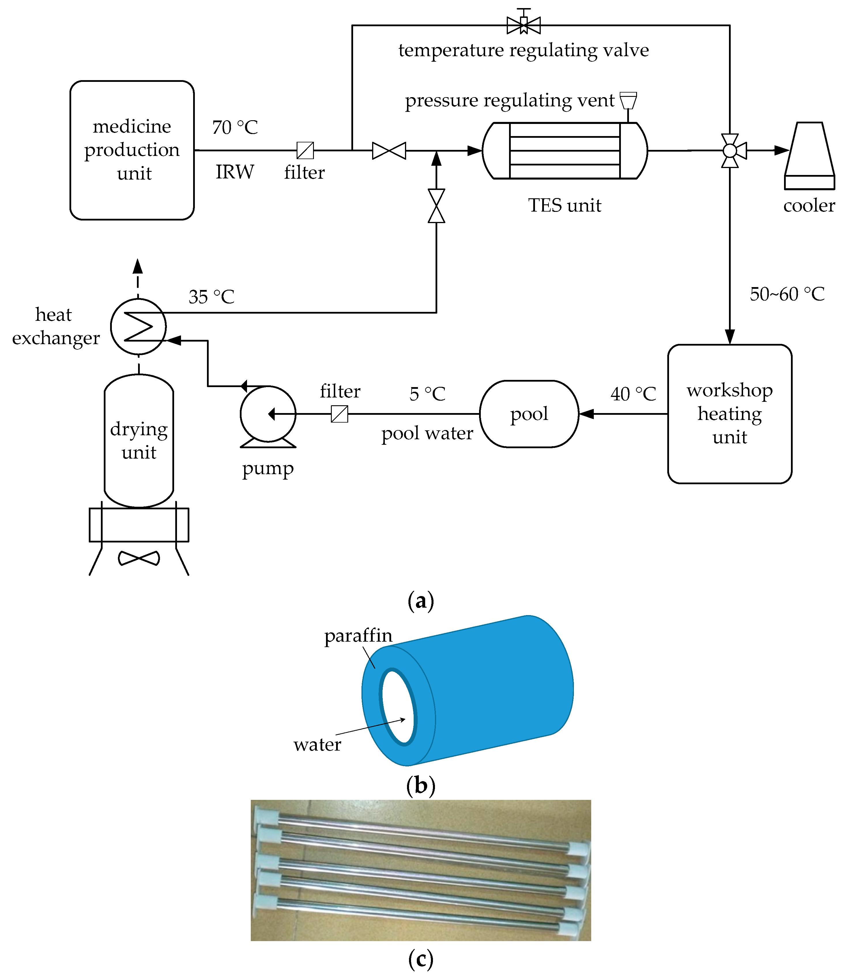
2. Problem Description and System Design
3. Mathematical Model
3.1. Heat Storage Process
- It is assumed that the paraffin wax is smooth and with constant physical properties.
- IRW and pool water are incompressible fluid and Newtonian fluid.
- The entrance effects of fluid flow and heat transfer are ignored.
- The initial temperature of the paraffin wax is uniform.
- The external wall of the shell is thermally insulated.
- The axial heat conductions of IRW, pool water, and paraffin wax are neglected.
- Natural convection when the phase change occurs in paraffin wax is not considered.
- The specific volumetric dilatation of paraffin wax is regarded as 0.
- (1)
- When , it is a heat storage in phase change process, then x in Equations (11) and (12) is replaced by before the next recurrence.
- (2)
- When , it is a heat transfer in single liquid phase, then , .
3.2. Heat Release Process
- (1)
- When , x in Equations (13) and (14) is replaced by before the next recurrence.
- (2)
- When , , .
3.3. Parameters Determination
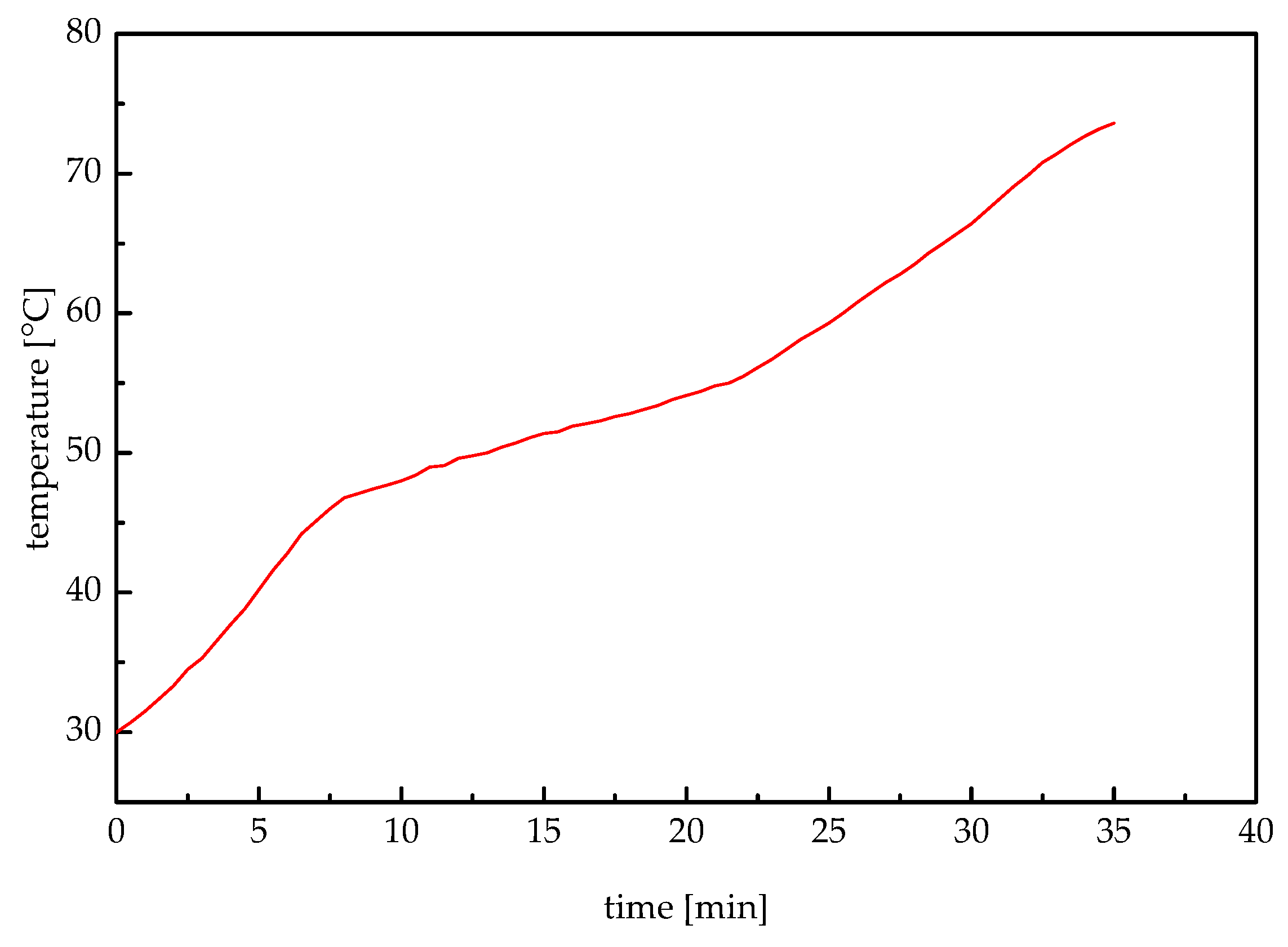
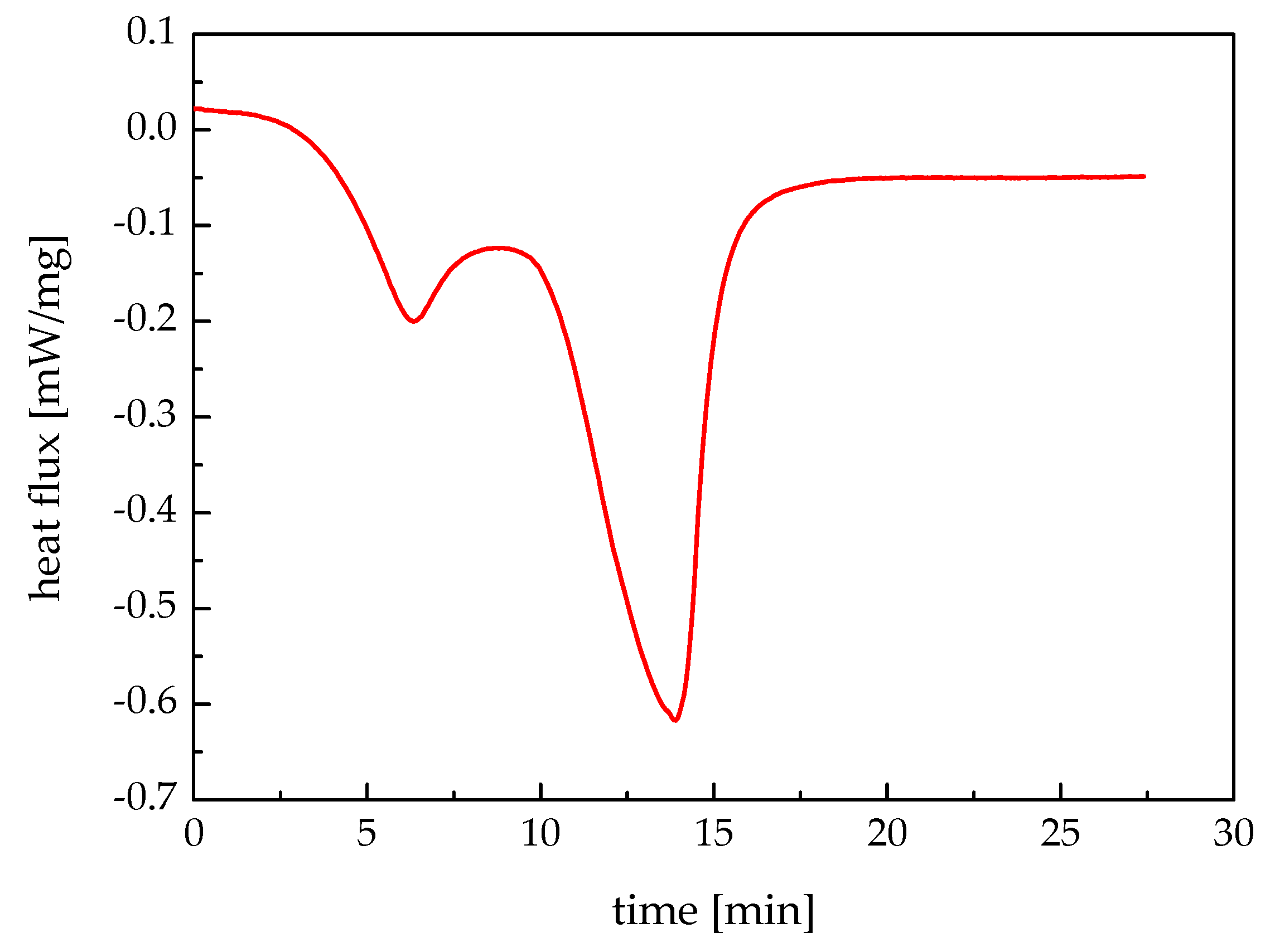
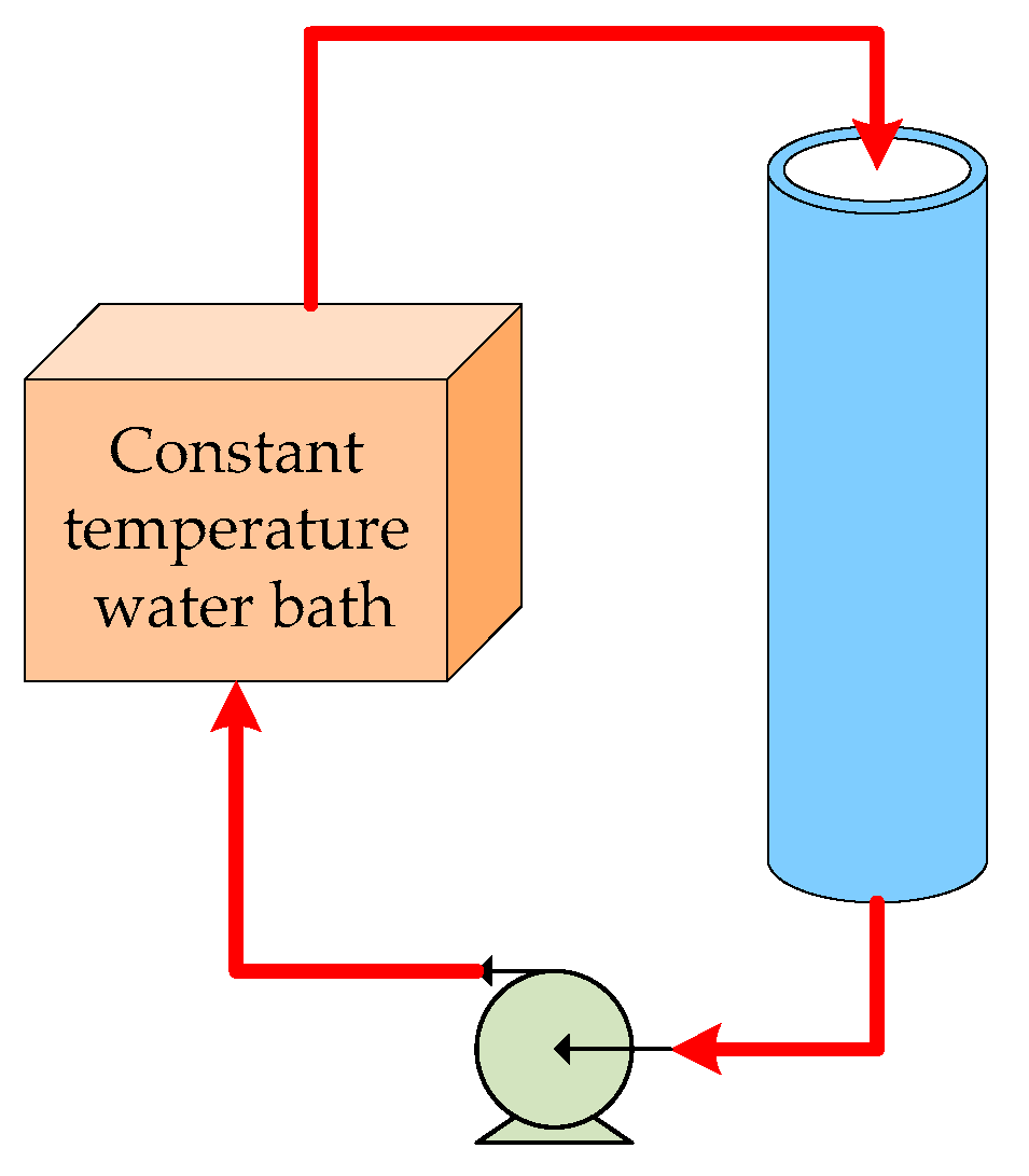
4. Model Validation
5. Results and Discussions
6. Conclusions
Acknowledgments
Author Contributions
Conflicts of Interest
Nomenclature
Variables
| b | specific energy consumption of medicine production unit [MJ/kg] |
| c | specific heat capacity of water [kJ/(kg·K)] |
| h | convection coefficient of IRW [W/(m2·K)] |
| convection coefficient of pool water [W/(m2·K)] | |
| H | latent heat of paraffin wax [kJ/kg] |
| L | length of a tube in TES unit [m] |
| m | flow rate of IRW into TES unit [kg/s] |
| flow rate of pool water into TES unit [kg/s] | |
| P | real yield of medicine production unit [kg/h] |
| Pr | rated yield of medicine production unit [kg/h] |
| ri | internal radius of tube [m] |
| ro | external radius of tube [m] |
| rp | melting radius of solid paraffin wax [m] |
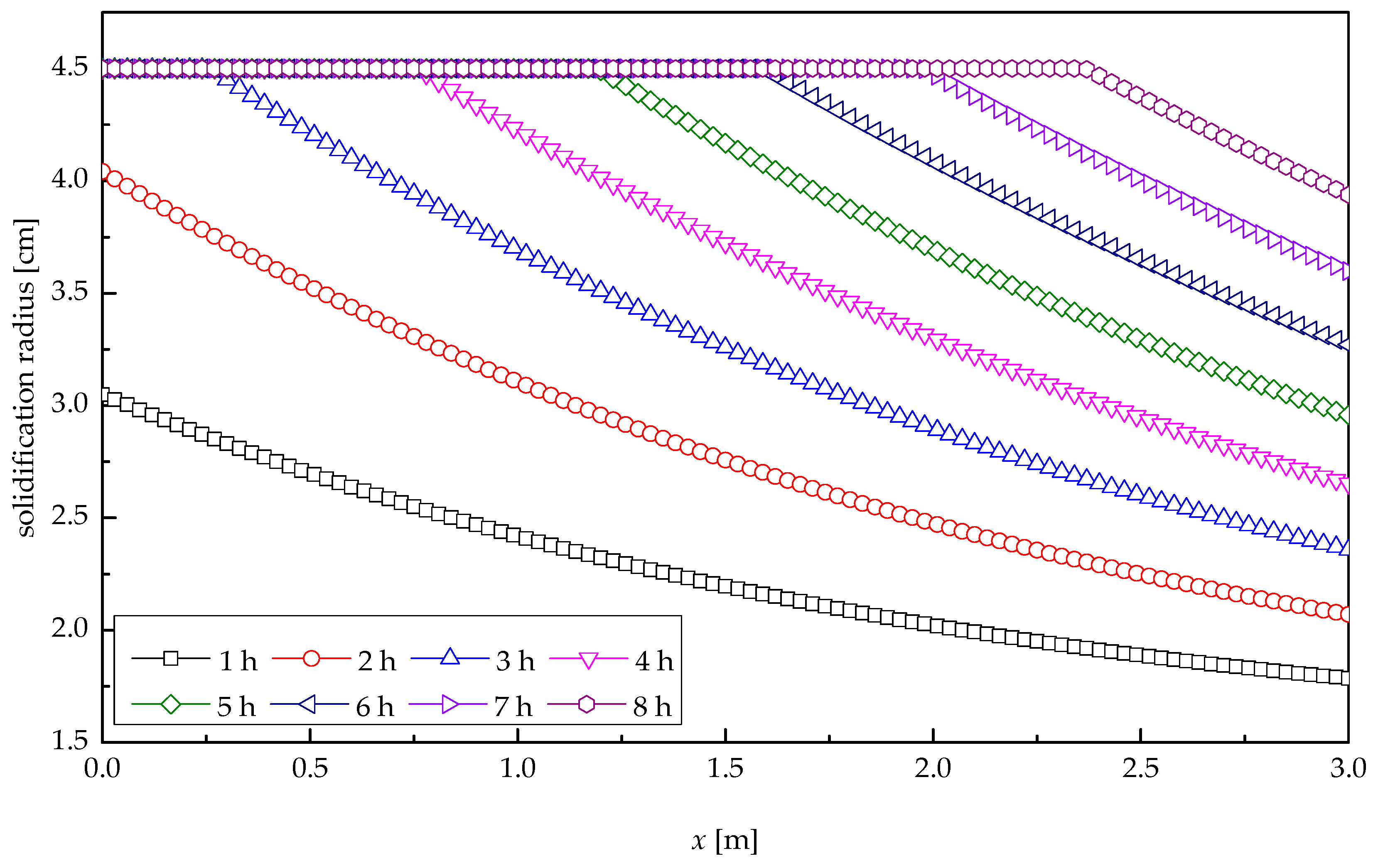
| solidification radius of liquid paraffin wax [m] | |
| r0 | internal radius of shell [m] |
| Rp | thermal resistance of paraffin wax [m2·K/W] |
| Rw | thermal resistance of IRW-tube heat transfer [m2·K/W] |
| tin | IRW temperature at TES unit inlet [°C] |
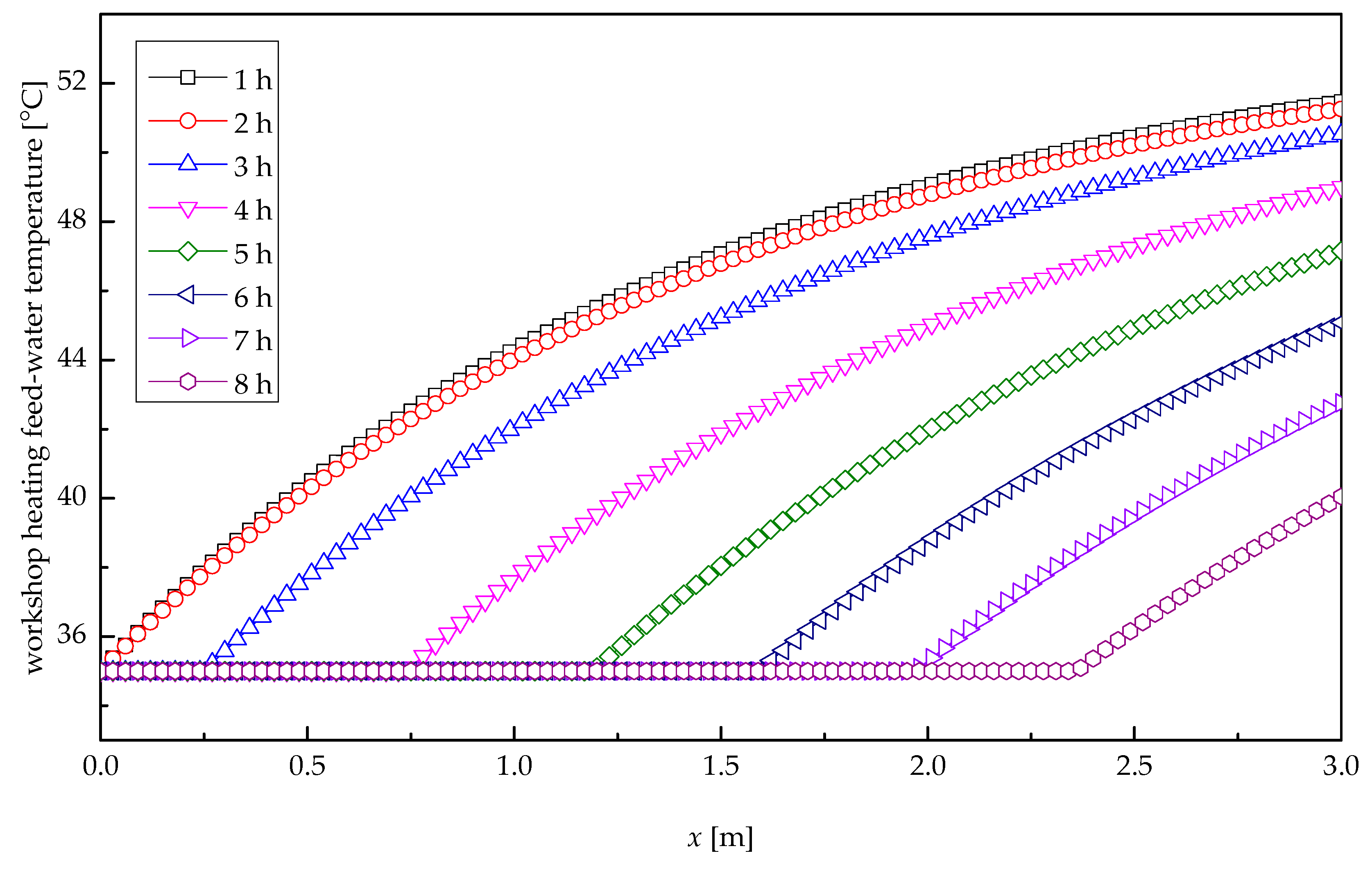
| pool water temperature at TES unit inlet [°C] | |
| tm | phase change temperature [°C] |
| ts | temperature of tube wall [°C] |
| tw | temperature of IRW [°C] |
| temperature of pool water [°C] | |
| x | axial direction |
| X | location at the maximum melting radius |
| location at the maximum solidification radius |
Greek Symbols
| θ | nondimensional yield of medicine production unit [–] |
| λ | thermal conductivity of solid paraffin wax [W/(m·K)] |
| thermal conductivity of liquid paraffin wax [W/(m·K)] | |
| ρ | paraffin wax density [kg/m3] |
| τ | time [s, h] |
| φ | energy saving rate [%] |
Abbreviations
| DSC | differential scanning calorimeter |
| IRW | industrial residual water |
| PCM | phase change material |
| TES | thermal energy storage |
References
- Erdem, H.H.; Dagdas, A.; Sevilgen, S.H.; Cetin, B.; Akkaya, A.V.; Sahin, B.; Teke, I.; Gungor, C.; Atas, S. Thermodynamic analysis of an existing coal-fired power plant for district heating/cooling application. Appl. Therm. Eng. 2010, 30, 181–187. [Google Scholar] [CrossRef]
- Arteconi, A.; Patteeuw, D.; Bruninx, K.; Delarue, E.; D’haeseleer, W.; Helsen, L. Active demand response with electric heating systems: Impact of market penetration. Appl. Energy 2016, 177, 636–648. [Google Scholar] [CrossRef]
- Joubert, E.C.; Hess, S.; van Niekerk, J.L. Large-scale solar water heating in South Africa: Status, barriers and recommendations. Renew. Energy 2016, 97, 809–822. [Google Scholar] [CrossRef]
- Ma, H.; Li, C.; Lu, W.; Zhang, Z.; Yu, S.; Du, N. Experimental study of a multi-energy complementary heating system based on a solar-groundwater heat pump unit. Appl. Therm. Eng. 2016, 109, 718–726. [Google Scholar] [CrossRef]
- Li, Y.; Xia, J.; Fang, H.; Su, Y.; Jiang, Y. Case study on industrial surplus heat of steel plants for district heating in Northern China. Energy 2016, 102, 397–405. [Google Scholar] [CrossRef]
- Togawa, T.; Fujita, T.; Dong, L.; Fujii, M.; Ooba, M. Feasibility assessment of the use of power plant-sourced waste heat for plant factory heating considering spatial configuration. J. Clean. Prod. 2014, 81, 60–69. [Google Scholar] [CrossRef]
- Eriksson, L.; Morandin, M.; Harvey, S. Targeting capital cost of excess heat collection systems in complex industrial sites for district heating applications. Energy 2015, 91, 465–478. [Google Scholar] [CrossRef]
- Sun, W.; Zhang, F. Design and thermodynamic analysis of a flash power system driven by process heat of continuous casting grade steel billet. Energy 2016, 116, 94–101. [Google Scholar] [CrossRef]
- Hosseini, S.R.; Amidpour, M.; Behbahaninia, A. Thermoeconomic analysis with reliability consideration of a combined power and multi stage flash desalination plant. Desalination 2011, 278, 424–433. [Google Scholar] [CrossRef]
- Chang, C.; Wang, Y.; Feng, X. Indirect heat integration across plants using hot water circles. Chin. J. Chem. Eng. 2015, 23, 992–997. [Google Scholar] [CrossRef]
- De Oliveira, R.G.; Generoso, D.J. Influence of the operational conditions on the performance of a chemisorption chiller driven by hot water between 65 °C and 80 °C. Appl. Energy 2016, 162, 257–265. [Google Scholar] [CrossRef]
- Sun, W.; Yue, X.; Wang, Y. Exergy efficiency analysis of ORC (Organic Rankine Cycle) and ORC-based combined cycles driven by low-temperature waste heat. Energy Convers. Manag. 2017, 135, 63–73. [Google Scholar] [CrossRef]
- Kim, D.K.; Lee, J.S.; Kim, J.; Kim, M.S.; Kim, M.S. Parametric study and performance evaluation of an organic Rankine cycle (ORC) system using low-grade heat at temperatures below 80 °C. Appl. Energy 2017, 189, 55–65. [Google Scholar] [CrossRef]
- Ergun, A.; Ozkaymak, M.; Koc, G.A.; Ozkan, S.; Kaya, D. Exergoeconomic analysis of a geothermal organic Rankine cycle power plant using the SPECO method. Environ. Prog. Sustain. Energy 2017, in press. [Google Scholar] [CrossRef]
- Sun, W.; Hong, Y.; Wang, Y. Operation optimization of steam accumulators as a thermal energy storage and buffer unit. Energies 2017, 10, 17. [Google Scholar] [CrossRef]
- Cheng, W.; Xie, B.; Zhang, R.; Xu, Z.; Xia, Y. Effect of thermal conductivities of shape stabilized PCM on under-floor heating system. Appl. Energy 2015, 144, 10–18. [Google Scholar] [CrossRef]
- Xia, Y.; Zhang, X.S. Experimental research on a double-layer radiant floor system with phase change material under heating mode. Appl. Therm. Eng. 2016, 96, 600–606. [Google Scholar] [CrossRef]
- Zhou, G.; He, J. Thermal performance of a radiant floor heating system with different heat storage materials and heating pipes. Appl. Energy 2015, 138, 648–660. [Google Scholar] [CrossRef]
- Furbo, S. Using water for heat storage in thermal energy storage (TES) systems. In Advances in Thermal Energy Storage Systems: Methods and Applications; Cabeza, L.F., Ed.; Woodhead Publishing: Cambridge, UK, 2015; pp. 31–47. [Google Scholar]
- Okello, D.; Foong, C.W.; Nydal, O.J.; Banda, E.J.K. An experimental investigation on the combined use of phase change material and rock particles for high temperature (~350 °C) heat storage. Energy Convers. Manag. 2014, 79, 1–8. [Google Scholar] [CrossRef]
- Guo, P.; Wang, Y.; Li, J.; Wang, Y. Thermodynamic analysis of a solar chimney power plant system with soil heat storage. Appl. Therm. Eng. 2016, 100, 1076–1084. [Google Scholar] [CrossRef]
- Ushak, S.; Fernández, A.G.; Grageda, M. Using molten salts and other liquid sensible storage media in thermal energy storage (TES) systems. In Advances in Thermal Energy Storage Systems: Methods and Applications; Cabeza, L.F., Ed.; Woodhead Publishing: Cambridge, UK, 2015; pp. 49–63. [Google Scholar]
- Zhao, C.Y.; Ji, Y.; Xu, Z. Investigation of the Ca(NO3)2–NaNO3 mixture for latent heat storage. Sol. Energy Mater. Sol. Cells 2015, 140, 281–288. [Google Scholar] [CrossRef]
- Sun, J.Q.; Zhang, R.Y.; Liu, Z.P.; Lu, G.H. Thermal reliability test of Al–34%Mg–6%Zn alloy as latent heat storage material and corrosion of metal with respect to thermal cycling. Energy Convers. Manage. 2007, 48, 619–624. [Google Scholar] [CrossRef]
- Li, X.; Zhou, Y.; Nian, H.; Ren, X.; Dong, O.; Hai, C.; Shen, Y.; Zeng, J. Phase change behavior of latent heat storage media based on calcium chloride hexahydrate composites containing strontium chloride hexahydrate and oxidation expandable graphite. Appl. Therm. Eng. 2016, 102, 38–44. [Google Scholar] [CrossRef]
- Ouchi, Y.; Someya, S.; Munakata, T.; Ito, H. Visualization of the phase change behavior of sodium acetate trihydrate for latent heat storage. Appl. Therm. Eng. 2015, 91, 547–555. [Google Scholar] [CrossRef]
- Aydin, A.A.; Okutan, H. High-chain fatty acid esters of myristoyl alcohol with even carbon number: Novel organic phase change materials for thermal energy storage—1. Sol. Energy Mater. Sol. Cells 2011, 95, 2752–2762. [Google Scholar] [CrossRef]
- Li, C.; Fu, L.; Ouyang, J.; Tang, A.; Yang, H. Kaolinite stabilized paraffin composite phase change materials for thermal energy storage. Appl. Clay Sci. 2015, 115, 212–220. [Google Scholar] [CrossRef]
- Kerskes, H.; Mette, B.; Bertsch, F.; Asenbeck, S.; Drück, H. Chemical energy storage using reversible solid/gas-reactions (CWS)—Results of the research project. Energy Proc. 2012, 30, 294–304. [Google Scholar] [CrossRef]
- Lefebvre, D.; Tezel, F.H. A review of energy storage technologies with a focus on adsorption thermal energy storage processes for heating applications. Renew. Sustain. Energy Rev. 2017, 67, 116–125. [Google Scholar] [CrossRef]
- Lim, K.; Che, J.; Lee, J. Experimental study on adsorption characteristics of a water and silica-gel based thermal energy storage (TES) system. Appl. Therm. Eng. 2017, 110, 80–88. [Google Scholar] [CrossRef]
- Sobolčiak, P.; Abdelrazeq, H.; Gözde Özerkan, N.; Ouederni, M.; Nógellová, Z.; AlMaadeed, M.A.; Karkri, M.; Krupa, I. Heat transfer performance of paraffin wax based phase change materials applicable in building industry. Appl. Therm. Eng. 2016, 107, 1313–1323. [Google Scholar] [CrossRef]
- Moreno, P.; Solé, C.; Castell, A.; Cabeza, L.F. The use of phase change materials in domestic heat pump and air-conditioning systems for short term storage: A review. Renew. Sustain. Energy Rev. 2014, 39, 1–13. [Google Scholar] [CrossRef]
- Aadmi, M.; Karkri, M.; El Hammouti, M. Heat transfer characteristics of thermal energy storage for PCM (phase change material) melting in horizontal tube: Numerical and experimental investigations. Energy 2015, 85, 339–352. [Google Scholar] [CrossRef]
- Trp, A. An experimental and numerical investigation of heat transfer during technical grade paraffin melting and solidification in a shell-and-tube latent thermal energy storage unit. Sol. Energy 2005, 79, 648–660. [Google Scholar] [CrossRef]
- He, B.; Martin, V.; Setterwall, F. Phase transition temperature ranges and storage density of paraffin wax phase change materials. Energy 2004, 29, 1785–1804. [Google Scholar] [CrossRef]
- Eftekhar, J.; Haji-Sheikh, A.; Lou, D.Y.S. Hear transfer enhancement in a paraffin wax thermal storage system. J. Sol. Energy Eng. 1984, 106, 299–306. [Google Scholar] [CrossRef]
- Himran, S.; Suwono, A.; Mansoori, G.A. Characterization of alkanes and paraffin waxes for application as phase change energy storage medium. Energy Sources 1994, 16, 117–128. [Google Scholar] [CrossRef]
- Zhou, D.; Zhao, C.Y.; Tian, Y. Review on thermal energy storage with phase change materials (PCMs) in building applications. Appl. Energy 2012, 92, 593–605. [Google Scholar] [CrossRef]
- Zhang, Y.; Faghri, A. Analysis of thermal energy storage system with conjugate turbulent forced convection. J. Thermophys. Heat Transf. 1995, 9, 722–726. [Google Scholar] [CrossRef]
- Liu, M.J.; Fan, L.W.; Zhu, Z.Q.; Feng, B.; Zhang, H.C.; Zeng, Y. A volume-shrinkage-based method for quantifying the inward solidification heat transfer of a phase change material filled in spherical capsules. Appl. Therm. Eng. 2016, 108, 1200–1205. [Google Scholar] [CrossRef]
- Wang, C.; Lin, T.; Li, N.; Zheng, H. Heat transfer enhancement of phase change composite material: Copper foam/paraffin. Renew. Energy 2016, 96, 960–965. [Google Scholar] [CrossRef]
- Song, S.H.; Liao, Q.; Shen, W.D. Laminar heat transfer and friction characteristics of microencapsulated phase change material slurry in a circular tube with twisted tape inserts. Appl. Therm. Eng. 2013, 50, 791–798. [Google Scholar] [CrossRef]
- Ma, Z.W.; Zhang, P. Modeling the heat transfer characteristics of flow melting of phase change material slurries in the circular tubes. Int. J. Heat Mass Transf. 2013, 64, 874–881. [Google Scholar] [CrossRef]
- Sun, D.; Wang, L. Research on heat transfer performance of passive solar collector-storage wall system with phase change materials. Energy Build. 2016, 119, 183–188. [Google Scholar] [CrossRef]
- Shaikh, S.; Lafdi, K. Effect of multiple phase change materials (PCMs) slab configurations on thermal energy storage. Energy Convers. Manag. 2006, 47, 2103–2117. [Google Scholar] [CrossRef]
- Regin, A.F.; Solanki, S.C.; Saini, J.S. Latent heat thermal energy storage using cylindrical capsule: Numerical and experimental investigations. Renew. Energy 2006, 31, 2025–2041. [Google Scholar] [CrossRef]


| Item | Symbol | Value | Unit |
|---|---|---|---|
| phase change temperature | tm | 47–56 | °C |
| latent heat | H | 171.4 | kJ/kg |
| density | ρ | 900 | kg/m3 |
| thermal conductivity (solid phase) | λ | 0.3 | W/(m·K) |
| thermal conductivity (liquid phase) | λ’ | 0.1 | W/(m·K) |
| Item | Symbol | Value | Unit |
|---|---|---|---|
| flow rate | m | 0.278 | kg/s |
| specific heat capacity | c | 4.18 | kJ/(kg·K) |
| convection coefficient | h | 498 | W/(m2·K) |
| IRW temperature at the inlet of TES unit | tin | 70 | °C |
| pool water temperature at the inlet of TES unit | t’in | 35 | °C |
| Item | Symbol | Value | Unit |
|---|---|---|---|
| tube length | L | 3000 | mm |
| internal radius of the interior tube | ri | 26 | mm |
| external radius of the interior tube | ro | 30 | mm |
| internal radius of the exterior shell | r0 | 45 | mm |
© 2017 by the authors. Licensee MDPI, Basel, Switzerland. This article is an open access article distributed under the terms and conditions of the Creative Commons Attribution (CC BY) license ( http://creativecommons.org/licenses/by/4.0/).
Share and Cite
Sun, W.; Zhao, Z.; Wang, Y. Thermal Analysis of a Thermal Energy Storage Unit to Enhance a Workshop Heating System Driven by Industrial Residual Water. Energies 2017, 10, 219. https://doi.org/10.3390/en10020219
Sun W, Zhao Z, Wang Y. Thermal Analysis of a Thermal Energy Storage Unit to Enhance a Workshop Heating System Driven by Industrial Residual Water. Energies. 2017; 10(2):219. https://doi.org/10.3390/en10020219
Chicago/Turabian StyleSun, Wenqiang, Zuquan Zhao, and Yanhui Wang. 2017. "Thermal Analysis of a Thermal Energy Storage Unit to Enhance a Workshop Heating System Driven by Industrial Residual Water" Energies 10, no. 2: 219. https://doi.org/10.3390/en10020219
APA StyleSun, W., Zhao, Z., & Wang, Y. (2017). Thermal Analysis of a Thermal Energy Storage Unit to Enhance a Workshop Heating System Driven by Industrial Residual Water. Energies, 10(2), 219. https://doi.org/10.3390/en10020219