A Maximum Efficiency Point Tracking Control Scheme Based on Different Cross Coupling of Dual-Receiver Inductive Power Transfer System


Abstract
:1. Introduction
- (1)
- When the receivers move along the transmitter track, the relative positions between the receivers and the transmitter track change from time to time. Therefore, the induced voltage on each receiver coil changes and this leads to diversity in the receiver currents. As a result, receiver currents will impose an induced voltage on each other. Then, the whole system will suffer from detuned conditions. As a result, both the system efficiency and output power capacity are affected.
- (2)
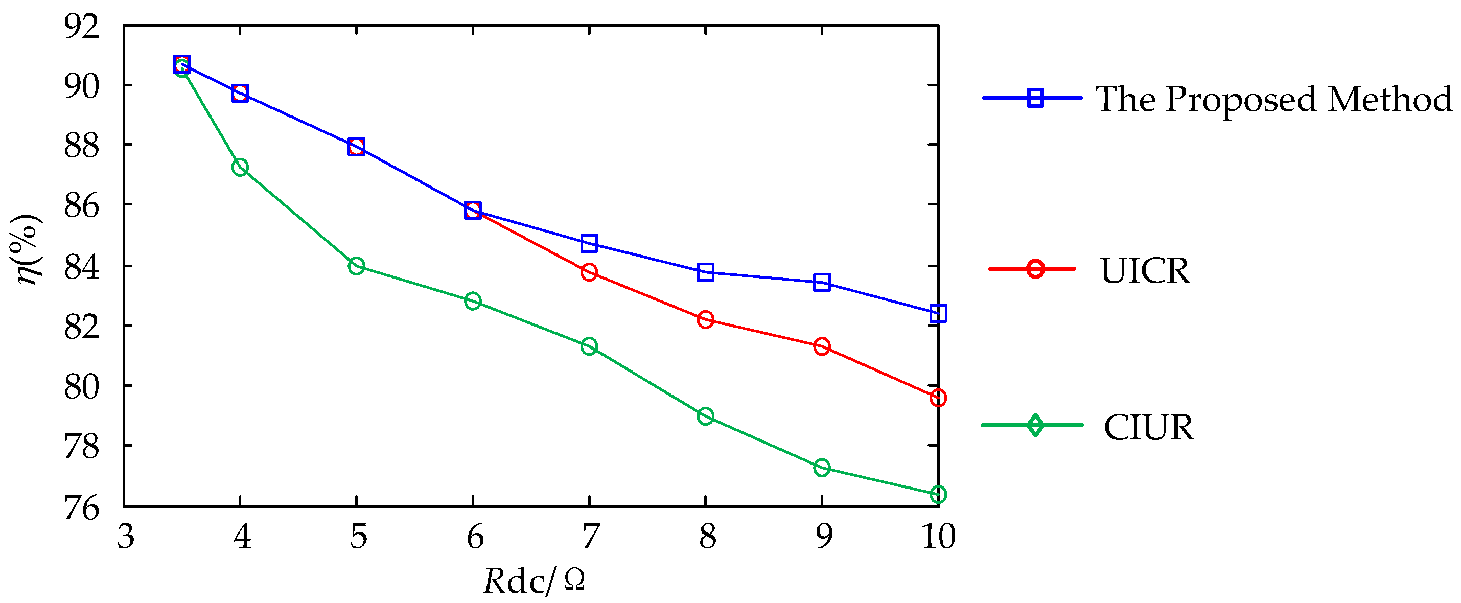
- With the different power demands during operation, the equivalent load of the train changes randomly, and may deviate from the designed optimal load value. The random load will greatly influence the system efficiency.
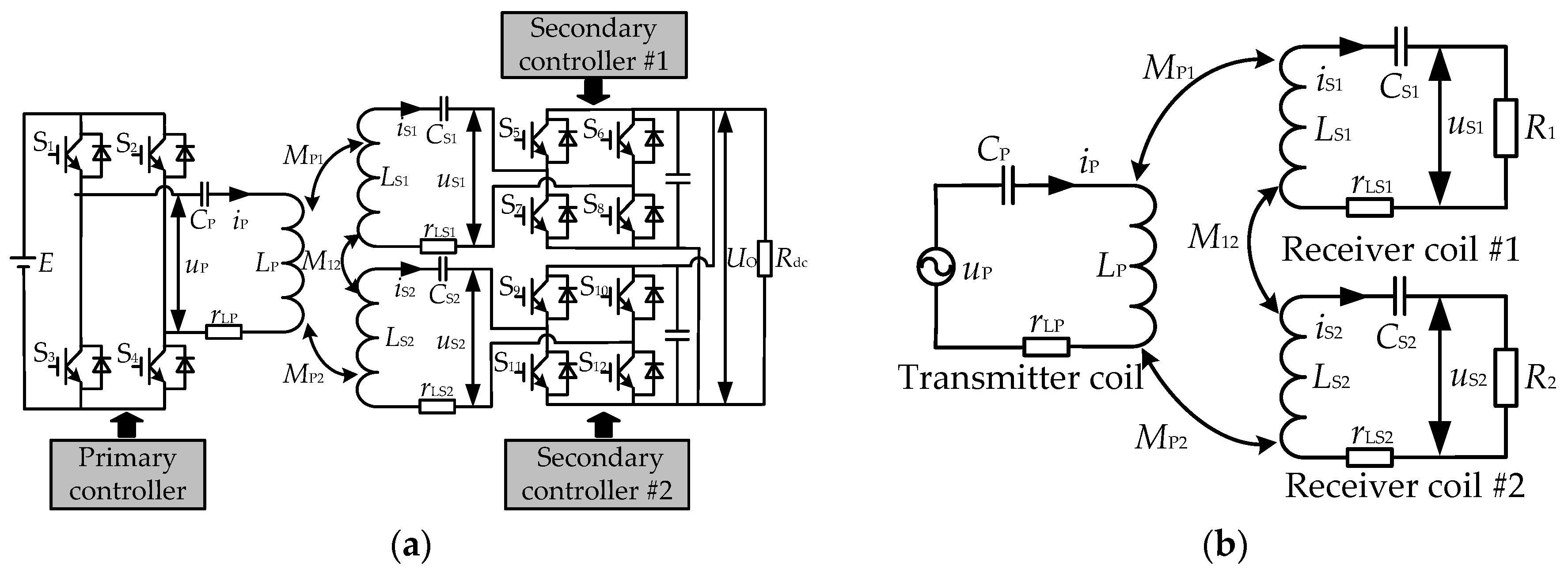
2. Analysis on Dual-Coil Receiver IPT System
2.1. Effect of the Cross Coupling between Two Coils
2.2. Self-Inductance Compensated Scenario
2.3. Cross Coupling Compensated Scenario
2.4. Different Mutual Inductance Scenario
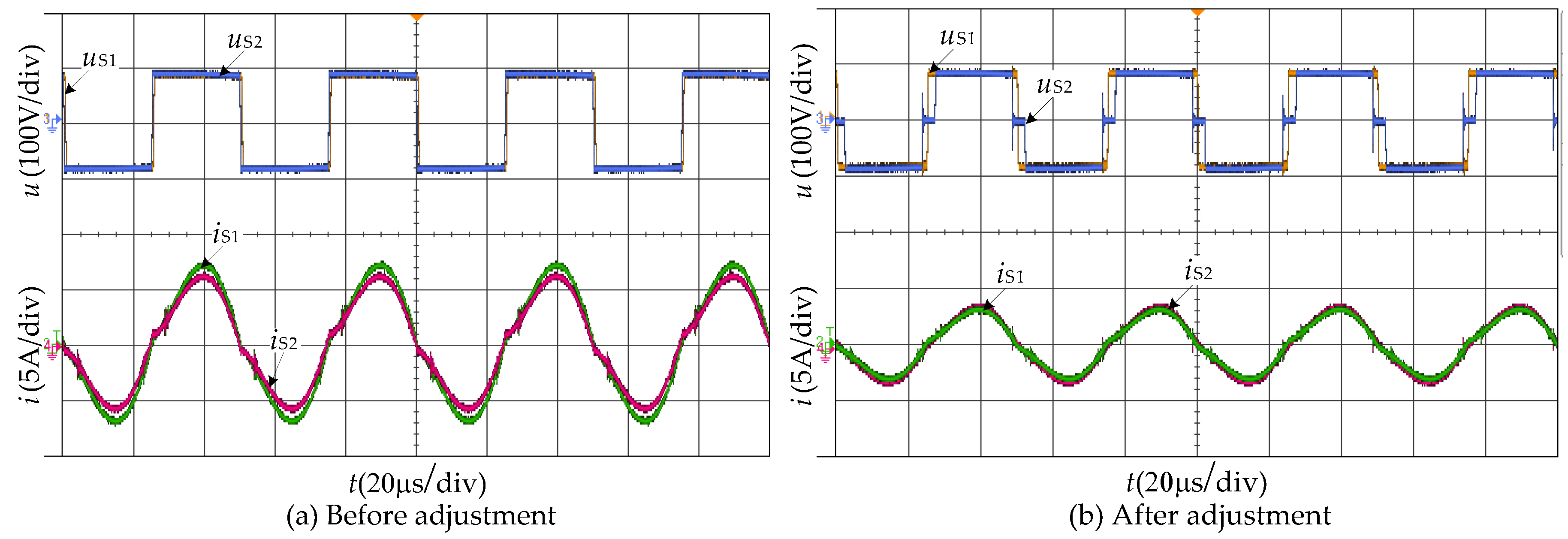
2.5. Adjust the Receiver Current
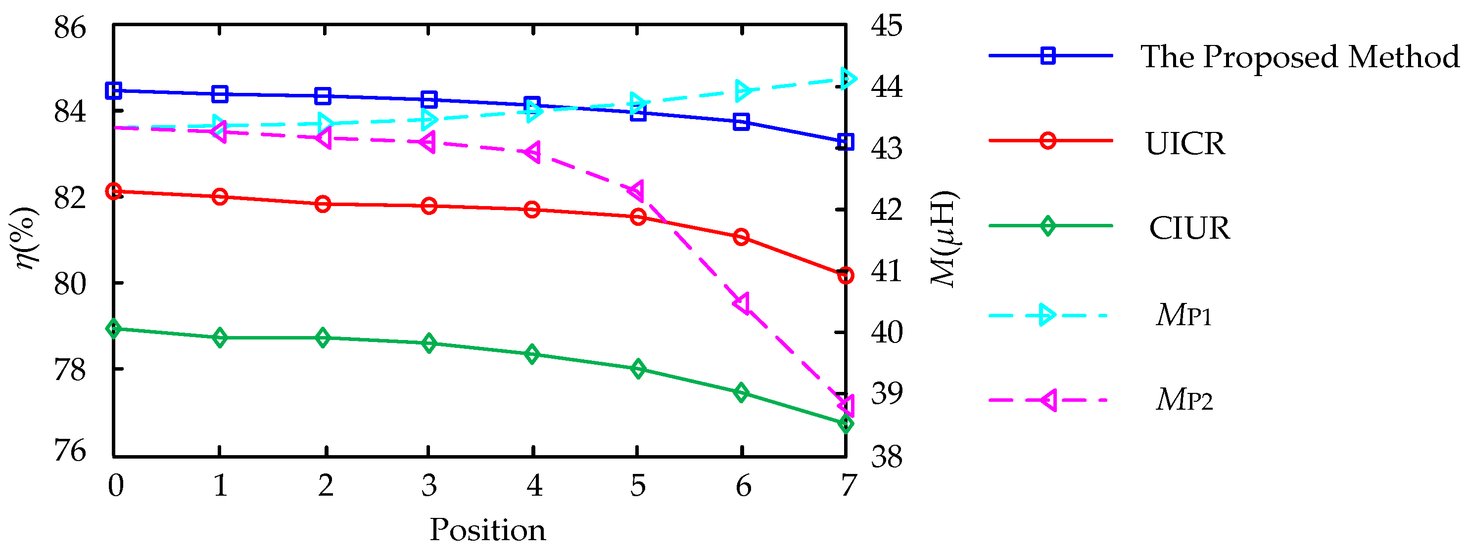
2.6. Maximum Efficiency Point
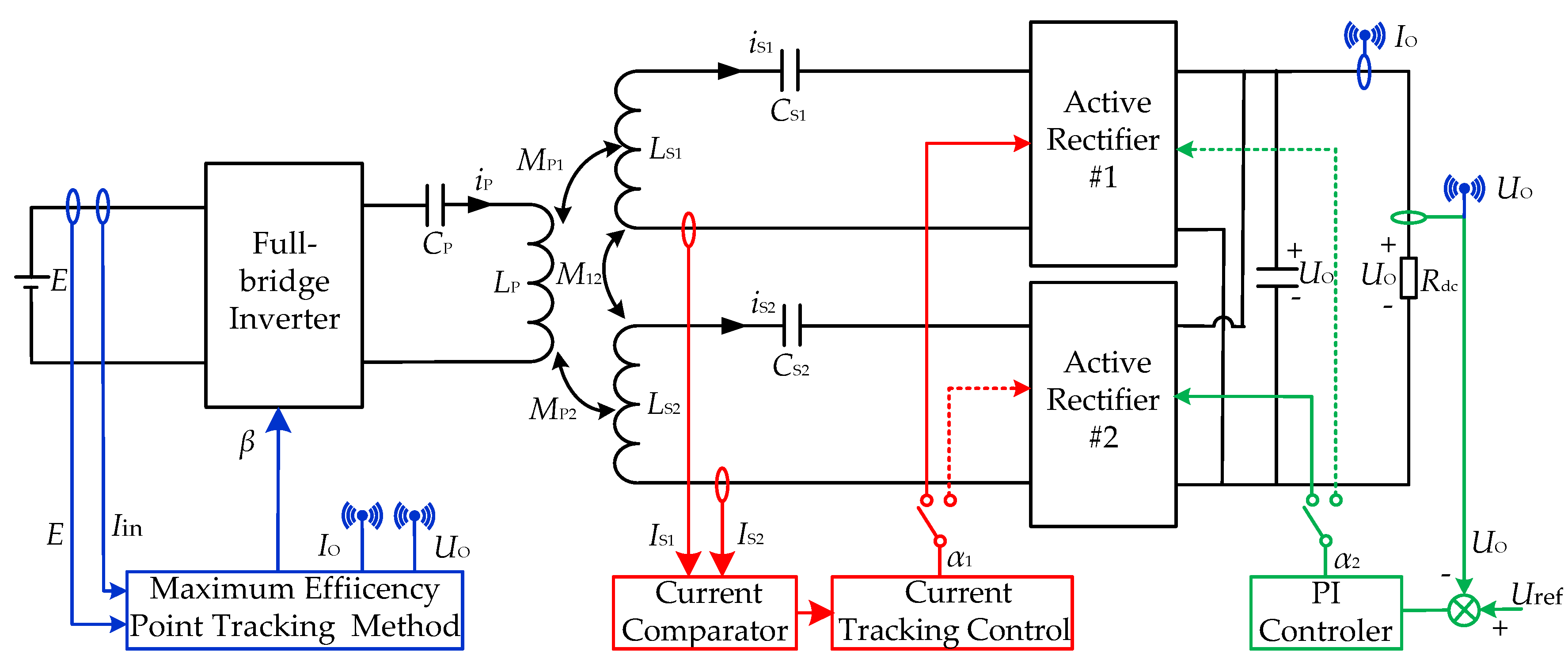
3. Control Method
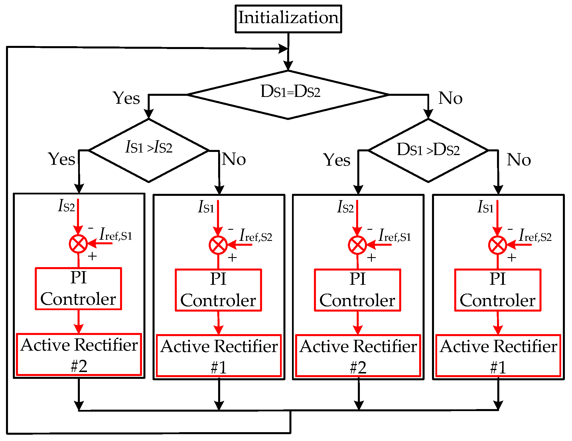
3.1. Active Rectifier Current Control Loop
3.2. Output Voltage Control Loop
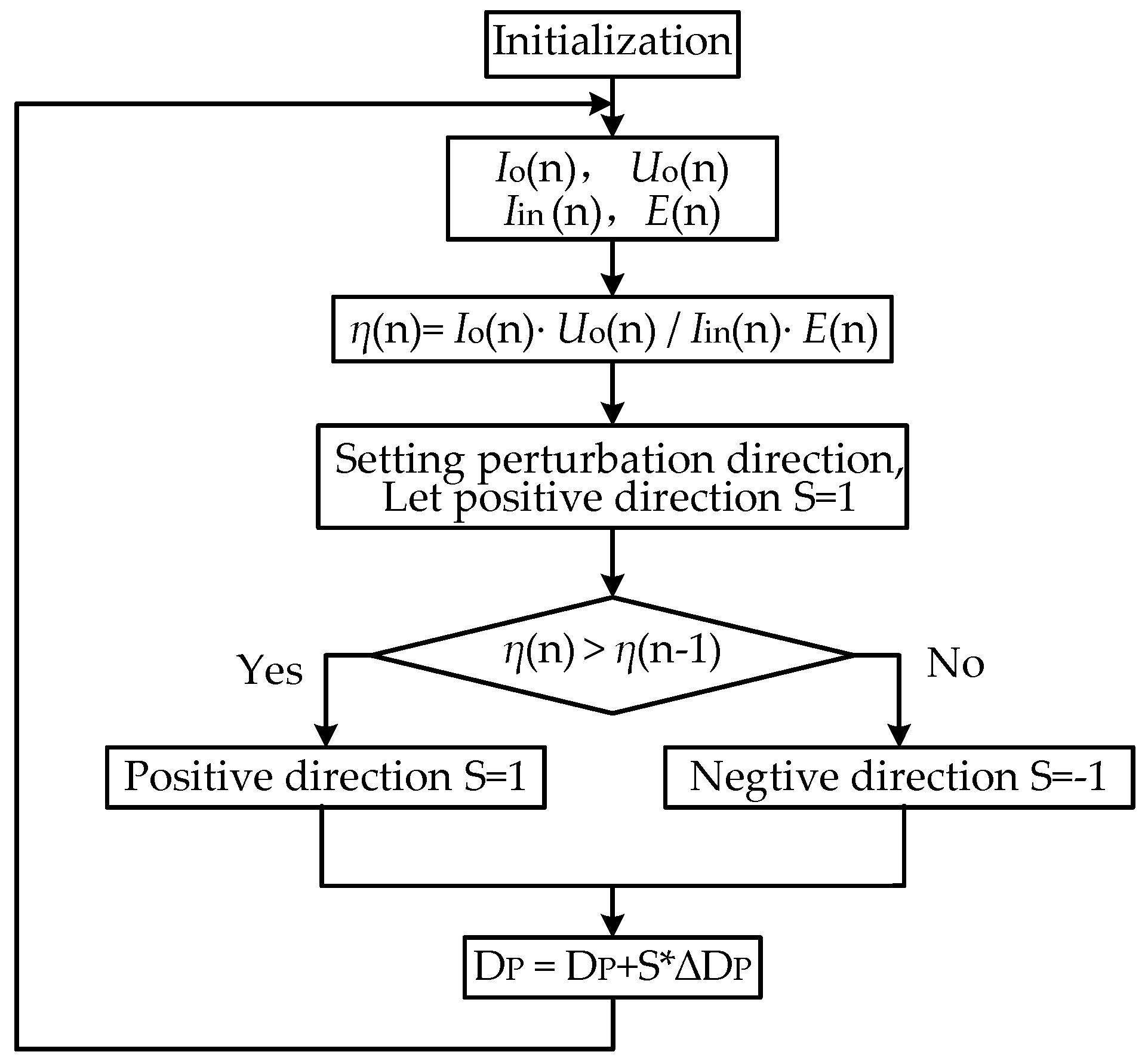
3.3. Perturbation and Observation Control Loop
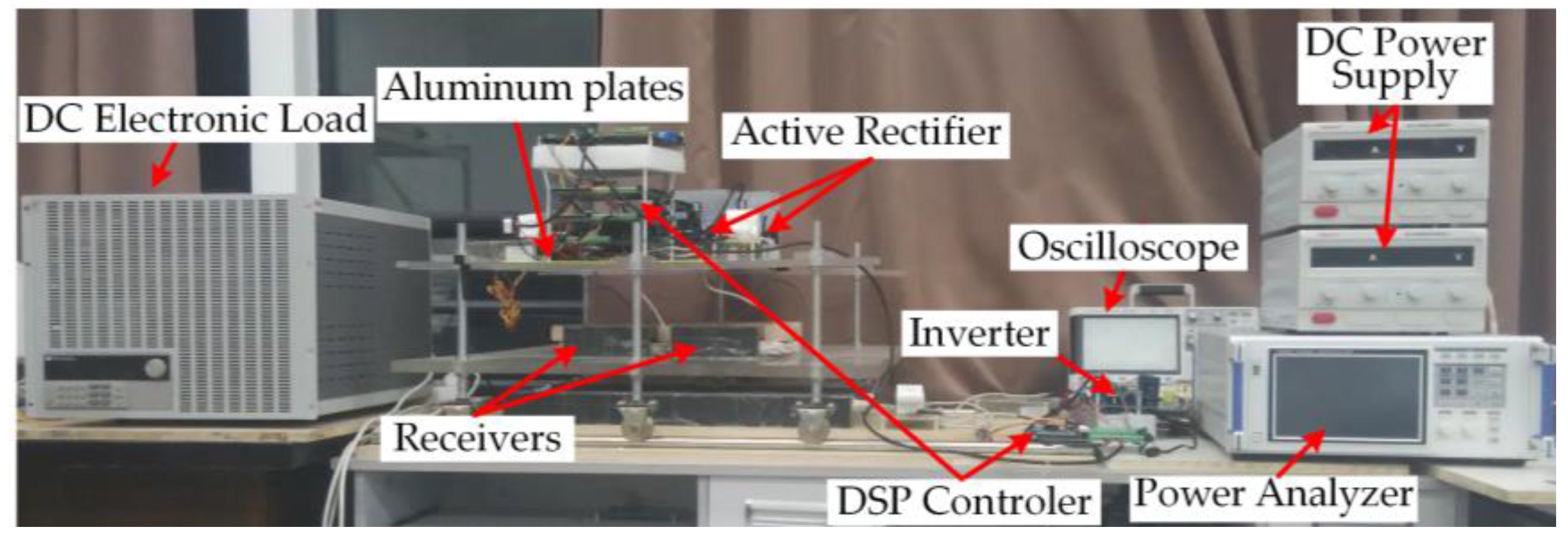
4. Experimental Verification
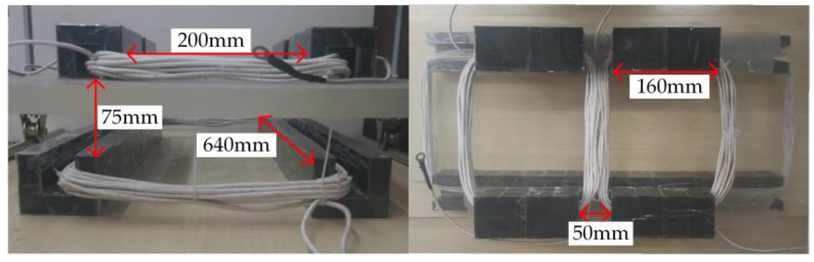
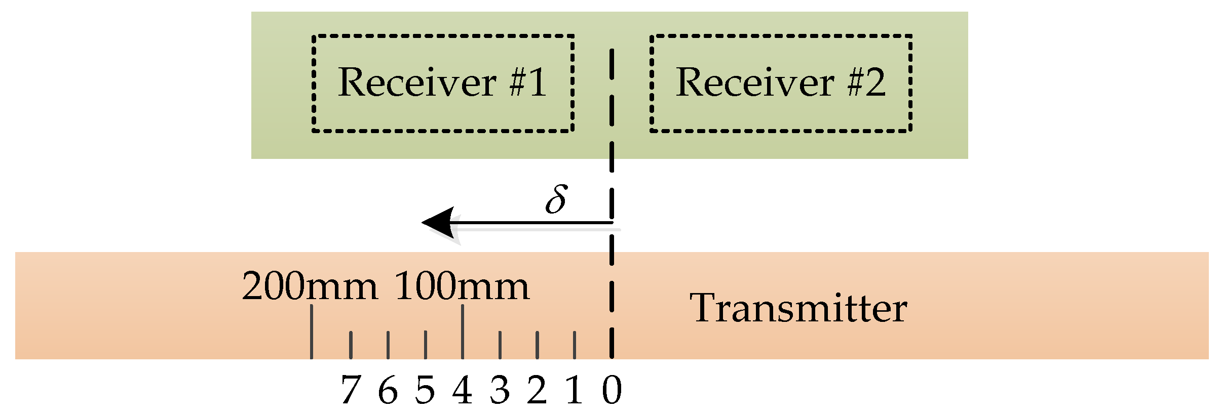
4.1. Experimental Parameters
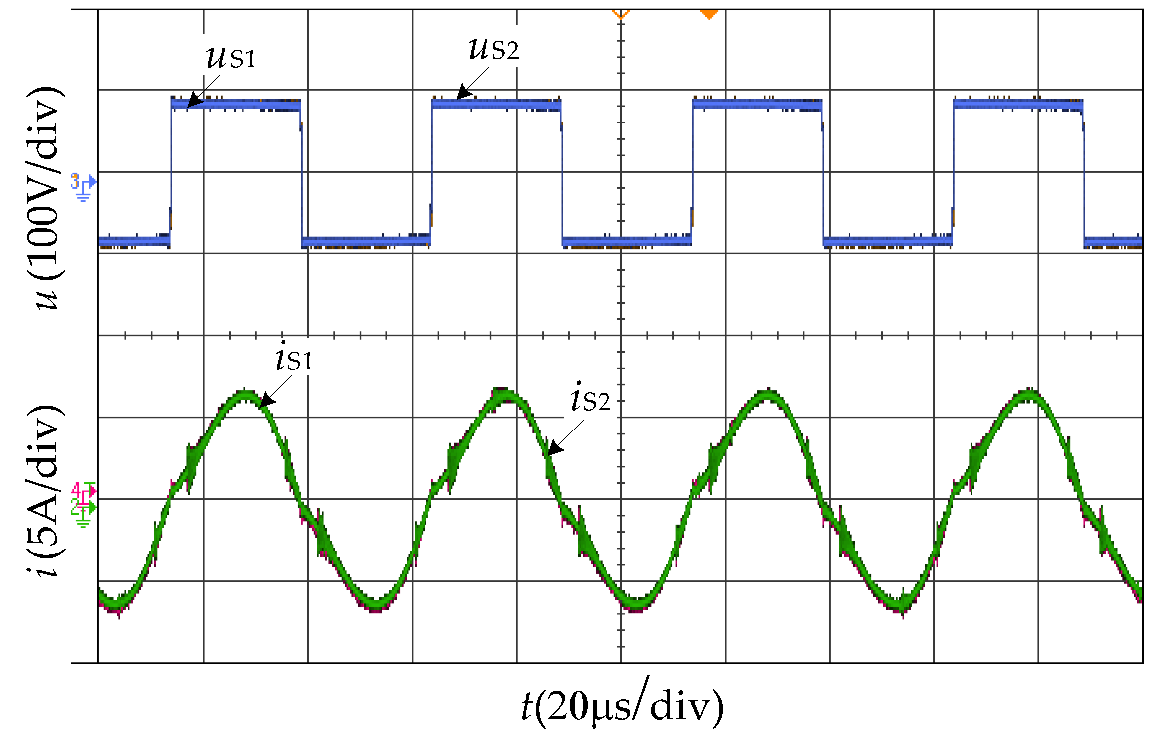
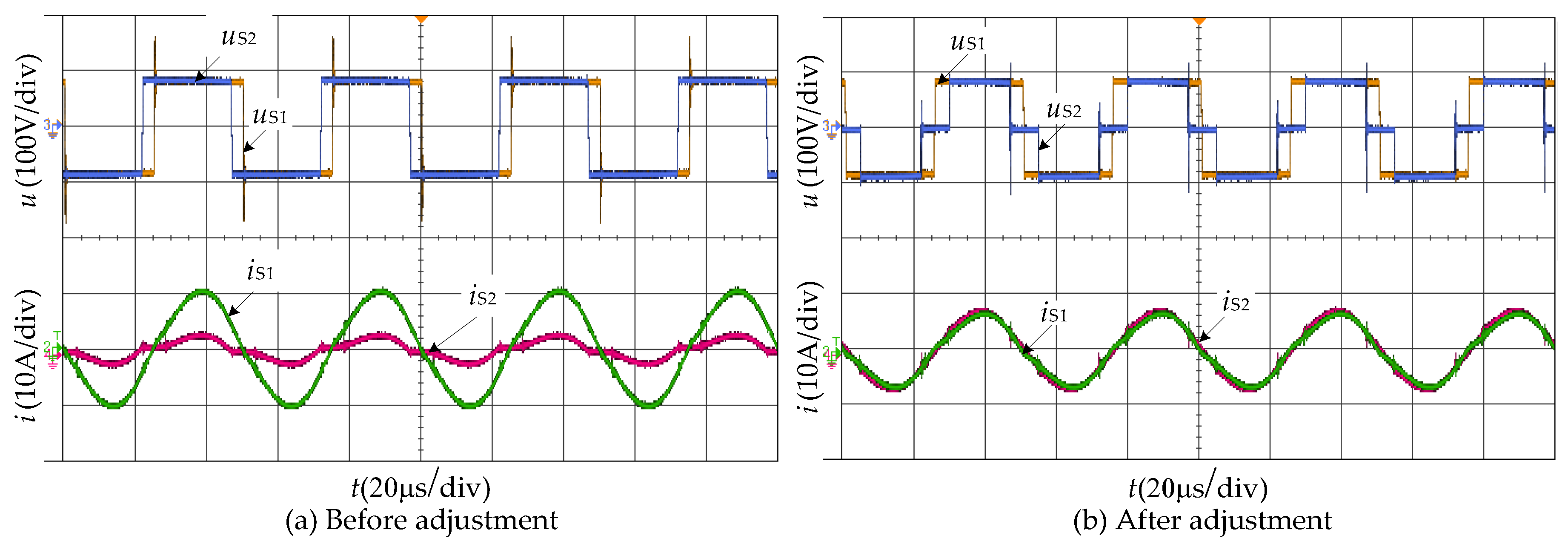
4.2. Experimental Results
- (1)
- Controlled inverter and uncontrolled active rectifier (CIUR) mode. The pulse widths of the MOSFETs of the active rectifier is set to 180 degree (passive-rectifier) and the conduction angle of the inverter is controlled to regulate the output voltage of DC load bus.
- (2)
- Uncontrolled inverter and controlled active rectifier (UICR) mode. The conduction angle of the inverter is set to 180 degree and the MOSFETs of the active rectifier are controlled to regulate the output voltage of DC load bus and regulate the receiver currents to be the same.
5. Conclusions
Acknowledgments
Author Contributions
Conflicts of Interest
References
- Covic, G.A.; Boys, J.T. Inductive Power Transfer. IEEE Proc. 2013, 101, 1276–1289. [Google Scholar] [CrossRef]
- Boys, J.T.; Covic, G.A.; Green, A.W. Stability and control of inductively coupled power transfer systems. IEE Proc. Electr. Power Appl. 2000, 147, 37–43. [Google Scholar] [CrossRef]
- Hui, S.; Ho, W.W. A new generation of universal contactless battery charging platform for portable consumer electronic equipment. IEEE Trans. Power Electron. 2005, 20, 620–627. [Google Scholar] [CrossRef]
- Hu, A.P.; Hussmann, S. Improved power flow control for contactless moving sensor applications. IEEE Power Electron. Lett. 2004, 2, 135–138. [Google Scholar] [CrossRef]
- Choi, S.Y.; Gu, B.W.; Jeong, S.Y.; Rim, C.T. Advances in Wireless Power Transfer Systems for Roadway-Powered Electric Vehicles. IEEE J. Emerg. Sel. Top. Power Electron. 2015, 3, 18–36. [Google Scholar] [CrossRef]
- Kim, J.H.; Lee, B.-S.; Lee, J.-H.; Lee, S.-H.; Park, C.-B.; Jung, S.-M.; Lee, S.-G.; Yi, K.-P.; Baek, J. Development of 1-MW Inductive Power Transfer System for a High-Speed Train. IEEE Trans. Ind. Electron. 2015, 62, 6242–6250. [Google Scholar] [CrossRef]
- Huh, J.; Lee, S.W.; Lee, W.Y.; Cho, G.H.; Rim, C.T. Narrow-Width Inductive Power Transfer System for Online Electrical Vehicles. IEEE Trans. Power Electron. 2011, 26, 3666–3679. [Google Scholar] [CrossRef]
- Woronowicz, K.; Safaee, A.; Dickson, T. A general approach to tuning of a dual secondary winding transformer for wireless power transfer. In Proceedings of the 2014 IEEE International Electric Vehicle Conference (IEVC), Florence, Italy, 17–19 December 2014.
- Monti, G.; Che, W.; Wang, Q.; Dionigi, M.; Mongiardo, M.; Perfetti, R.; Chang, Y. Wireless power transfer between one transmitter and two receivers: Optimal analytical solution. Wirel. Power Transf. 2016, 3, 63–73. [Google Scholar] [CrossRef]
- Fu, M.; Zhang, T.; Ma, C.; Zhu, X. Efficiency and optimal loads analysis for multiple-receiver wireless power transfer systems. IEEE Trans. Microw. Theory Tech. 2015, 63, 801–812. [Google Scholar] [CrossRef]
- Ahn, D.; Hong, S. Effect of coupling between multiple transmitters or multiple receivers on wireless power transfer. IEEE Trans. Ind. Electron. 2013, 60, 2602–2613. [Google Scholar] [CrossRef]
- Fu, M.; Zhang, T.; Zhu, X.; Luk, P.C.-K.; Ma, C. Compensation of Cross Coupling in Multiple-Receiver Wireless Power Transfer Systems. IEEE Trans. Ind. Inform. 2016, 12, 474–482. [Google Scholar] [CrossRef]
- Kim, J.; Son, H.-C.; Kim, D.-H.; Park, Y.-J. Impedance matching considering cross coupling for wireless power transfer to multiple receivers. In Proceedings of the 2013 IEEE Wireless Power Transfer (WPT), Perugia, Italy, 15–16 May 2013; pp. 226–229.
- Ean, K.K.; Chuan, B.T.; Imura, T.; Hori, Y. Impedance matching and power division algorithm considering cross coupling for wireless power transfer via magnetic resonance. In Proceedings of the 2012 IEEE 34th International Telecommunications Energy Conference (INTELEC), Scottsdale, AZ, USA, 30 September–4 October 2012.
- Buja, G.; Bertoluzzo, M.; Mude, K.N. Design and Experimentation of WPT Charger for Electric City Car. IEEE Trans. Ind. Electron. 2015, 12, 7436–7447. [Google Scholar] [CrossRef]
- Fu, M.; Yin, H.; Zhu, X.; Ma, C. Analysis and tracking of optimal load in wireless power transfer systems. IEEE Trans. Power Electron. 2015, 30, 3952–3963. [Google Scholar] [CrossRef]
- Stoecklin, S.; Volk, T.; Yousaf, A.; Reindl, L. A Maximum Efficiency Point Tracking System for Wireless Powering of Biomedical Implants. Procedia Eng. 2015, 120, 451–454. [Google Scholar] [CrossRef]
- Stoecklin, S.; Yousaf, A.; Volk, T.; Reindl, L. Efficient Wireless Powering of Biomedical Sensor Systems for Multichannel Brain Implants. IEEE Trans. Instrum. Meas. 2016, 65, 754–764. [Google Scholar] [CrossRef]
- Li, H.; Li, J.; Wang, K.; Chen, W.; Yang, X. A maximum efficiency point tracking control scheme for wireless power transfer systems using magnetic resonant coupling. IEEE Trans. Power Electron. 2015, 30, 3998–4008. [Google Scholar] [CrossRef]
- Diekhans, T.; De Doncker, R.W. A dual-side controlled inductive power transfer system optimized for large coupling factor variations. In Proceedings of the 2014 IEEE Energy Conversion Congress and Exposition (ECCE), Pittsburgh, PA, USA, 14–18 September 2014; pp. 652–659.
- Erickson, R.W.; Maksimovic, D. Fundamentals of Power Electronics; Kluwer Academic Publishers: New York, NY, USA, 2001; pp. 712–713. [Google Scholar]


| Parameters | Value |
|---|---|
| The input voltage of inverter (E/V) | 150 |
| Operating frequency (f/kHz) | 20 |
| Inductance of transmitter coil (LP/μH) | 465.17 |
| Compensating capacitor of transmitter coil (CP/nF) | 136.13 |
| Inductance of receiver coil 1 (LS1/μH) | 222.23 |
| Inductance of receiver coil 2 (LS2/μH) | 222.54 |
| Crossing coupling between dual-coil receiver (M12/μH) | 21.15 |
| Compensating capacitor of receiver coil 1 (CS1/μF) | 315.02 |
| Compensating capacitor of receiver coil 2 (CS2/μF) | 315.03 |
| DC load (Rdc/Ω) | 3.5–10 |
| Position/(mm) | Mutual Inductance | Before Adjustment | After Adjustment | |||
|---|---|---|---|---|---|---|
| MP1/μH | MP2/μH | Output Power of Rectifier #1/(W) | Output Power of Rectifier #2/(W) | Output Power of Rectifier #1/(W) | Output Power of Rectifier #2/(W) | |
| δ = 0 | 43.33 | 43.32 | 336 | 337 | 336 | 337 |
| δ = 100 | 43.59 | 42.92 | 365 | 305 | 343 | 319 |
| δ = 175 | 44.12 | 38.82 | 542 | 123 | 347 | 315 |
© 2017 by the authors. Licensee MDPI, Basel, Switzerland. This article is an open access article distributed under the terms and conditions of the Creative Commons Attribution (CC BY) license ( http://creativecommons.org/licenses/by/4.0/).
Share and Cite
Mai, R.; Ma, L.; Liu, Y.; Yue, P.; Cao, G.; He, Z. A Maximum Efficiency Point Tracking Control Scheme Based on Different Cross Coupling of Dual-Receiver Inductive Power Transfer System. Energies 2017, 10, 217. https://doi.org/10.3390/en10020217
Mai R, Ma L, Liu Y, Yue P, Cao G, He Z. A Maximum Efficiency Point Tracking Control Scheme Based on Different Cross Coupling of Dual-Receiver Inductive Power Transfer System. Energies. 2017; 10(2):217. https://doi.org/10.3390/en10020217
Chicago/Turabian StyleMai, Ruikun, Linsen Ma, Yeran Liu, Pengfei Yue, Guangzhong Cao, and Zhengyou He. 2017. "A Maximum Efficiency Point Tracking Control Scheme Based on Different Cross Coupling of Dual-Receiver Inductive Power Transfer System" Energies 10, no. 2: 217. https://doi.org/10.3390/en10020217
APA StyleMai, R., Ma, L., Liu, Y., Yue, P., Cao, G., & He, Z. (2017). A Maximum Efficiency Point Tracking Control Scheme Based on Different Cross Coupling of Dual-Receiver Inductive Power Transfer System. Energies, 10(2), 217. https://doi.org/10.3390/en10020217