Modelling the Small Throw Fault Effect on the Stability of a Mining Roadway and Its Verification by In Situ Investigation


Abstract
:1. Introduction
2. Weakening of Rock in a Fault Zone
3. Research in the Mine
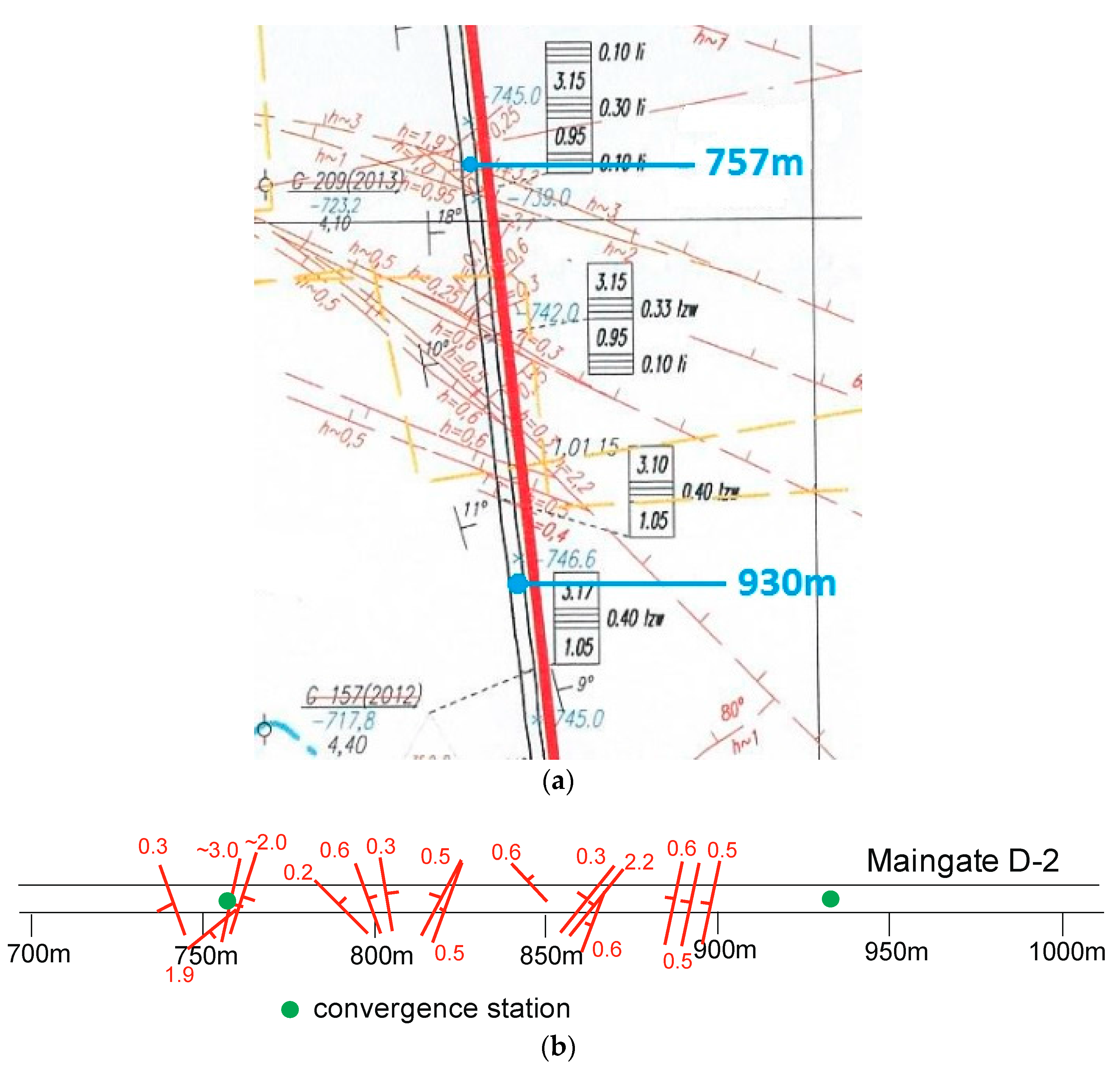
3.1. Geological Conditions in the Area
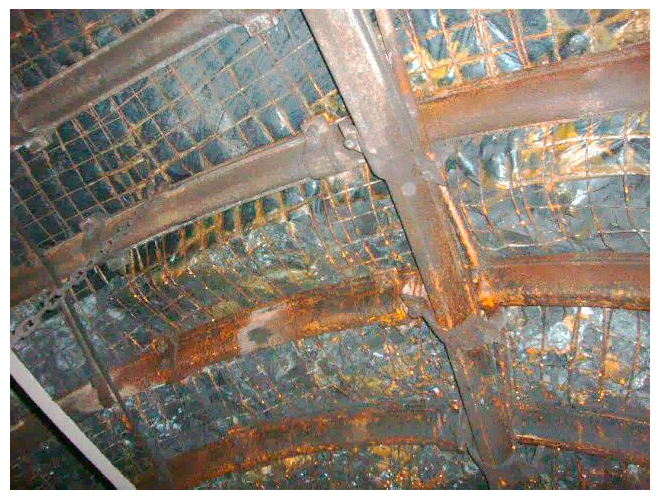
3.2. The Maingate D-2 Support
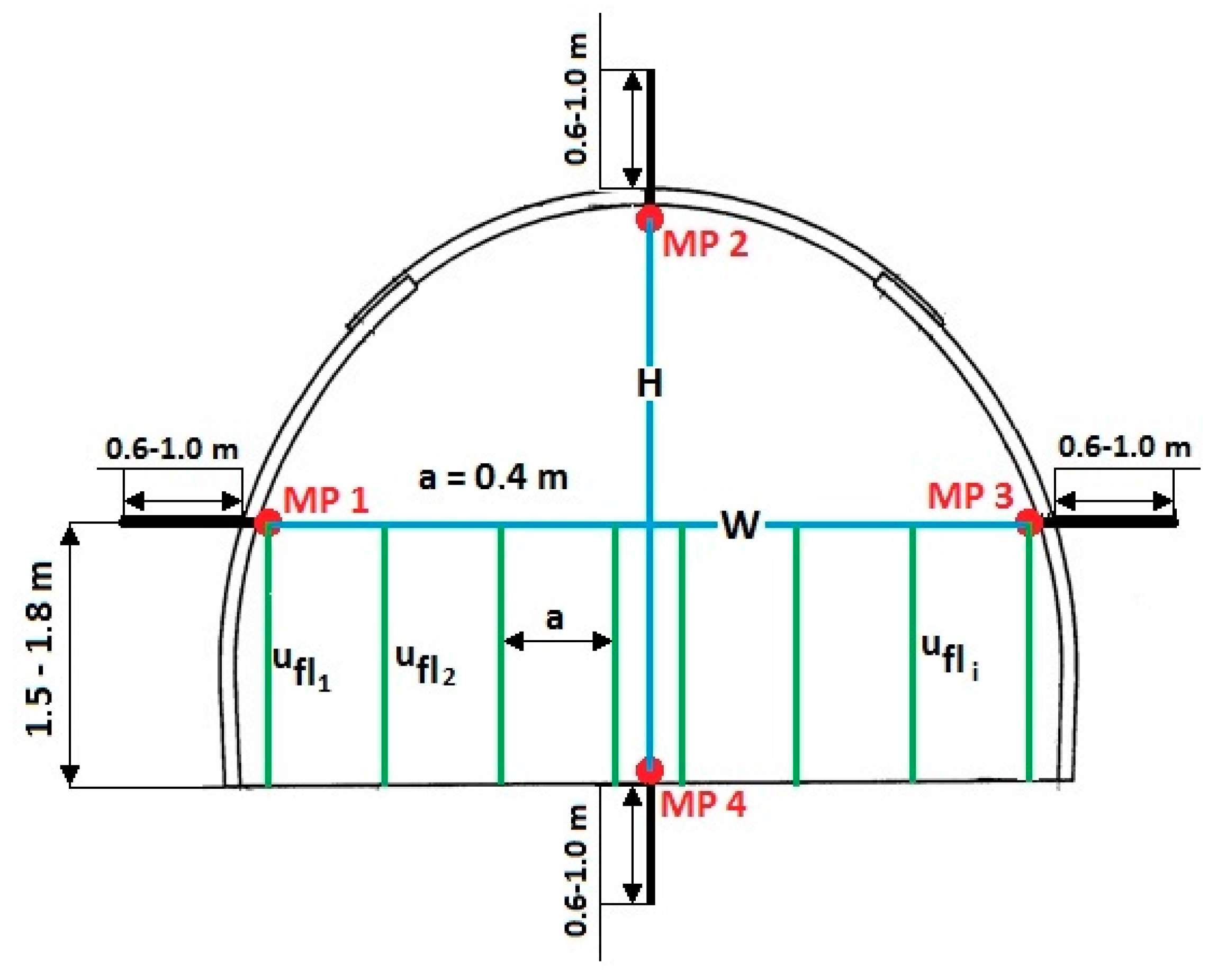
3.3. The In Situ Measurement Methodology
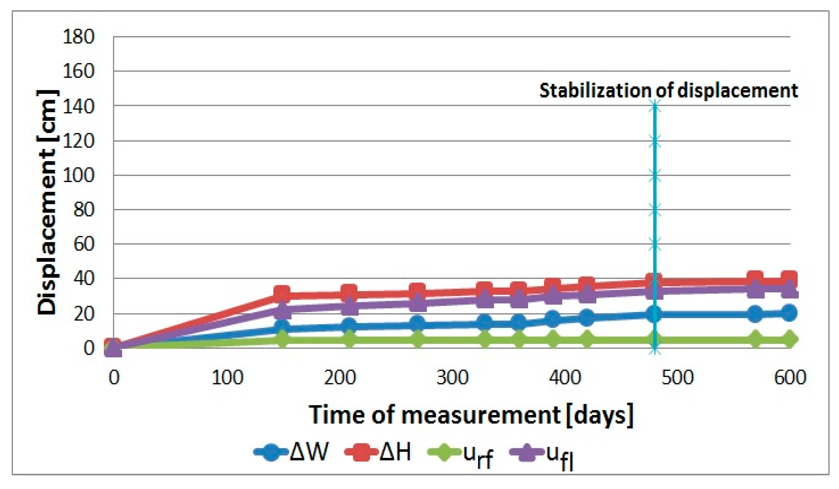
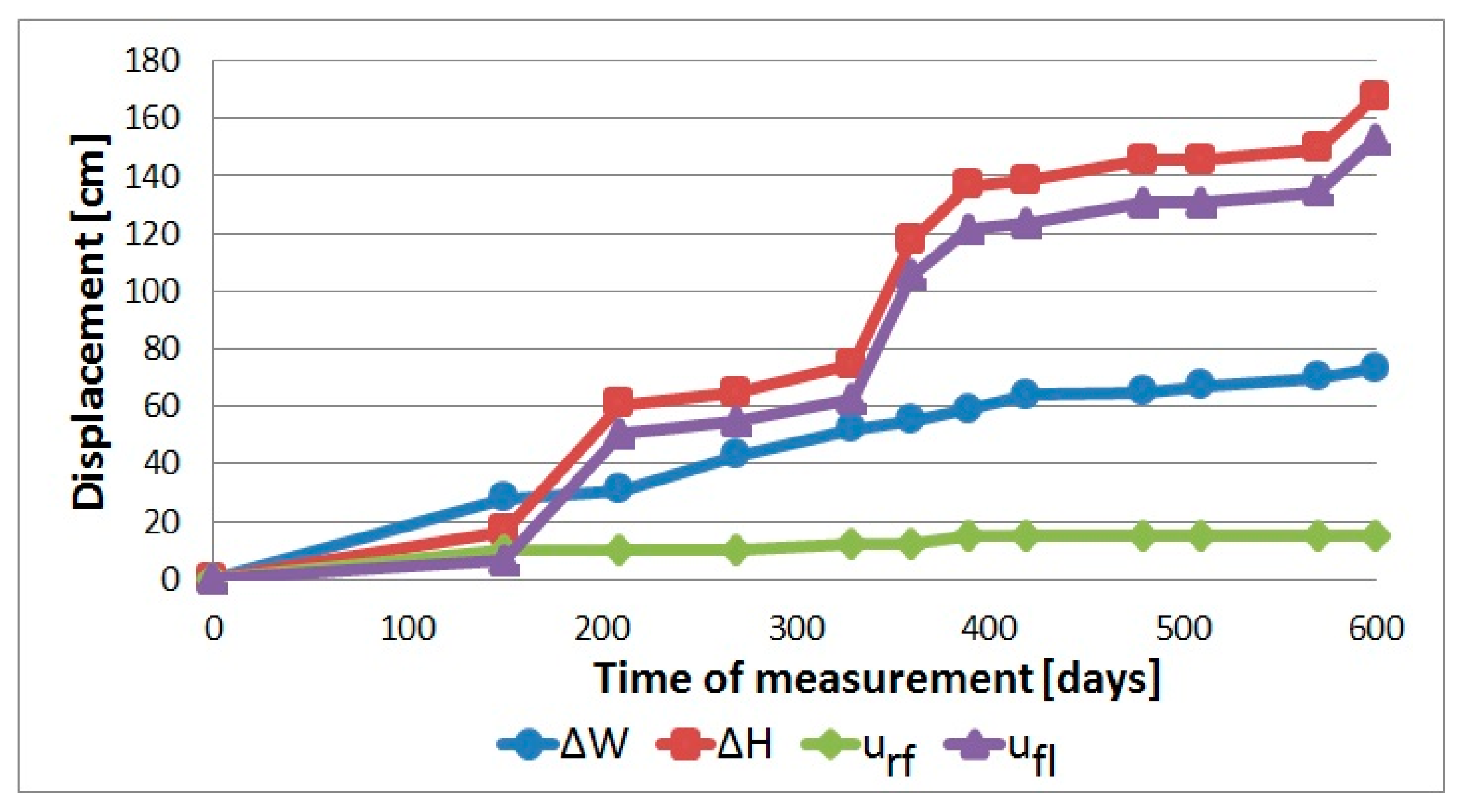
3.4. Results of Convergence Measurements
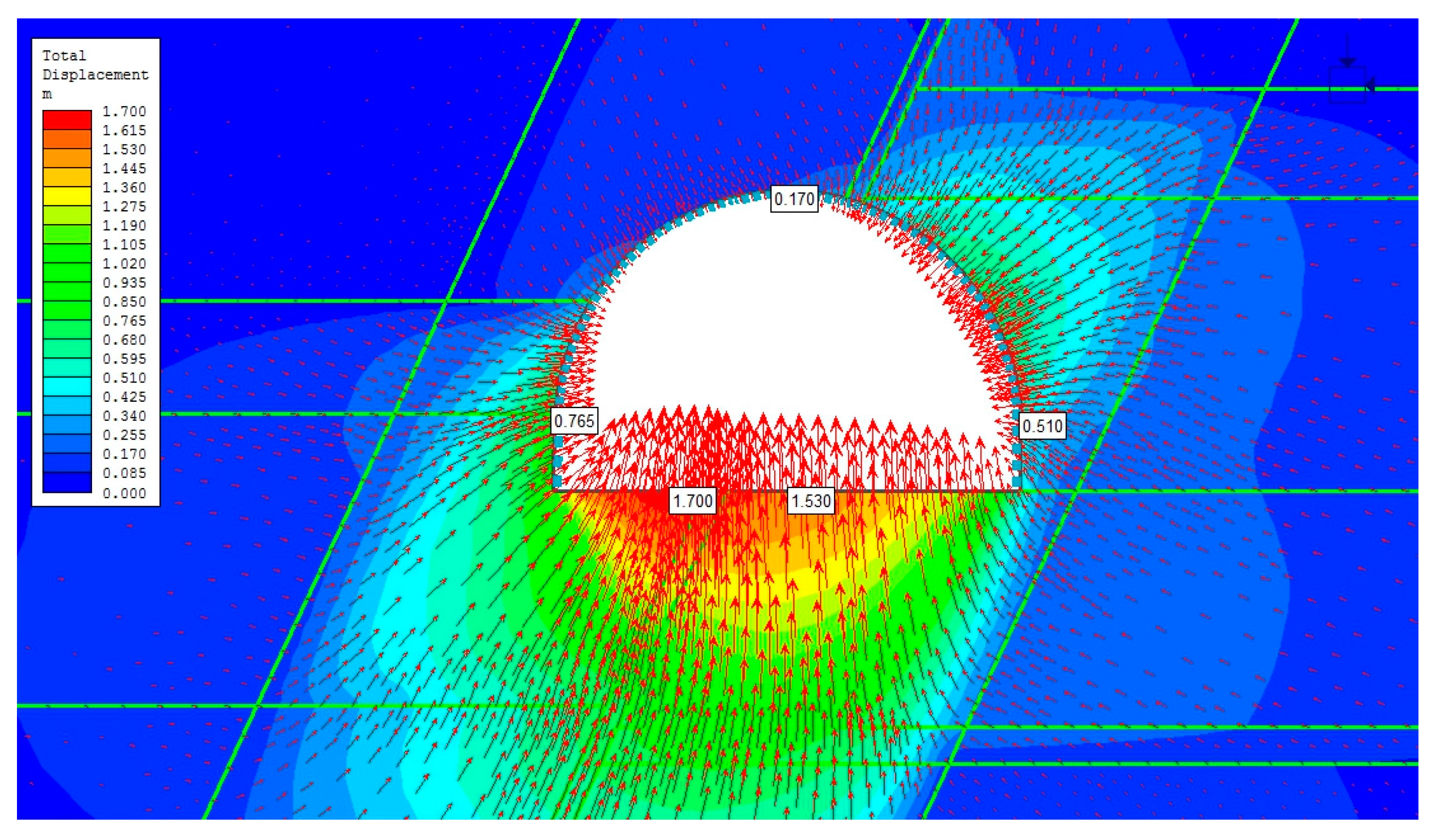
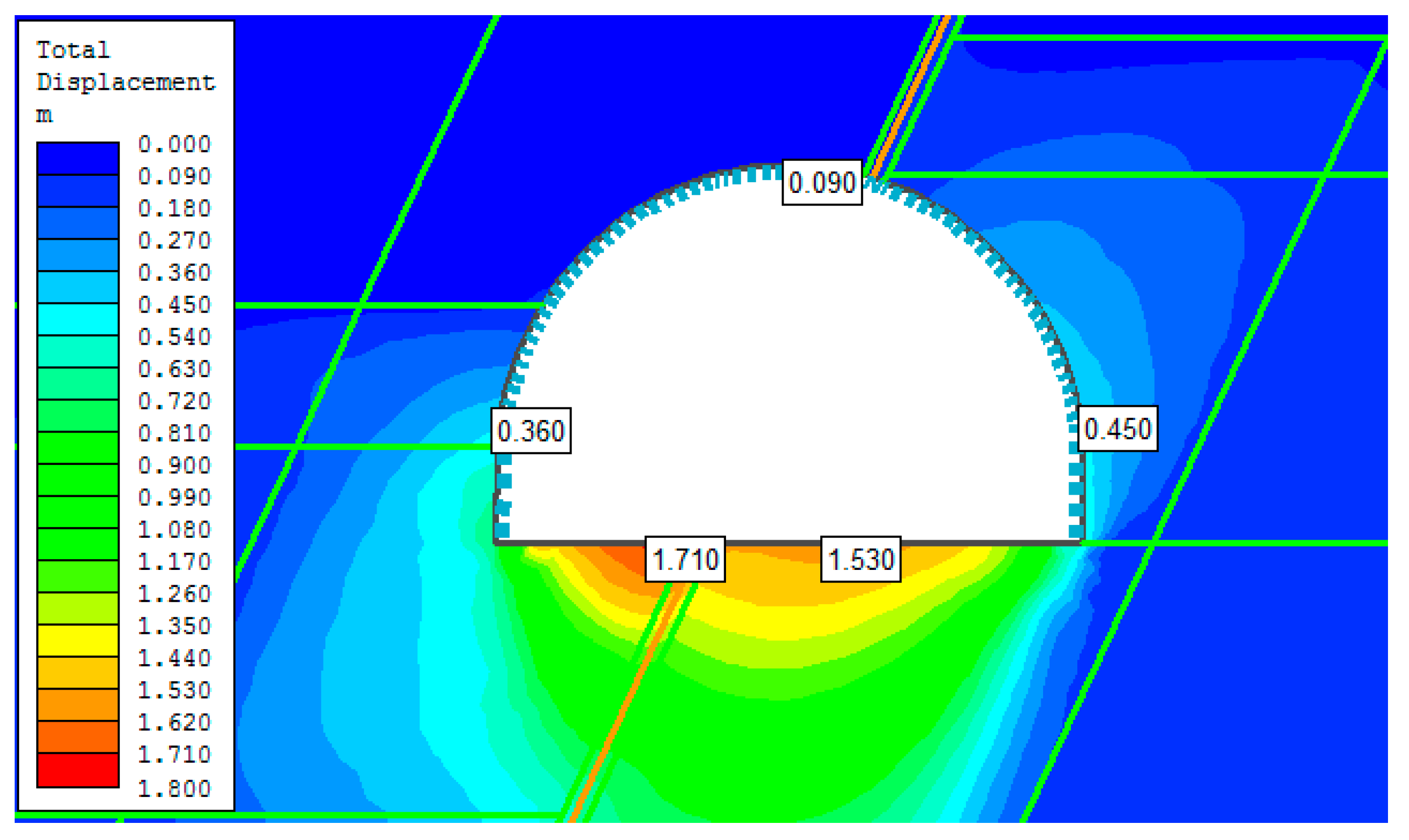
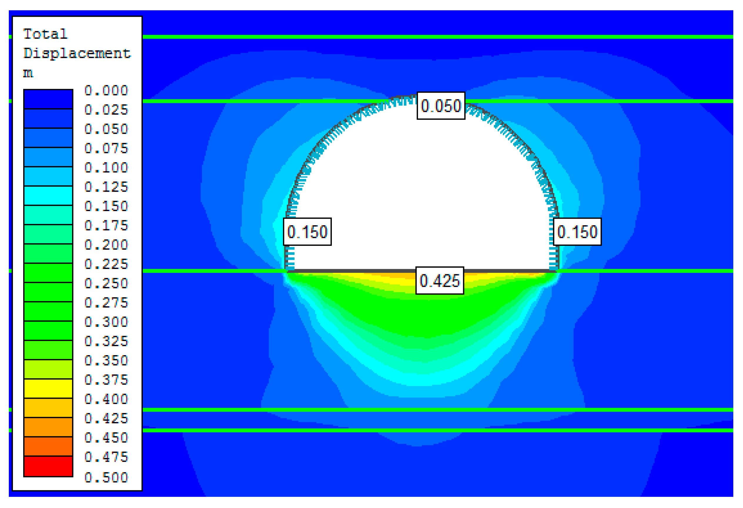
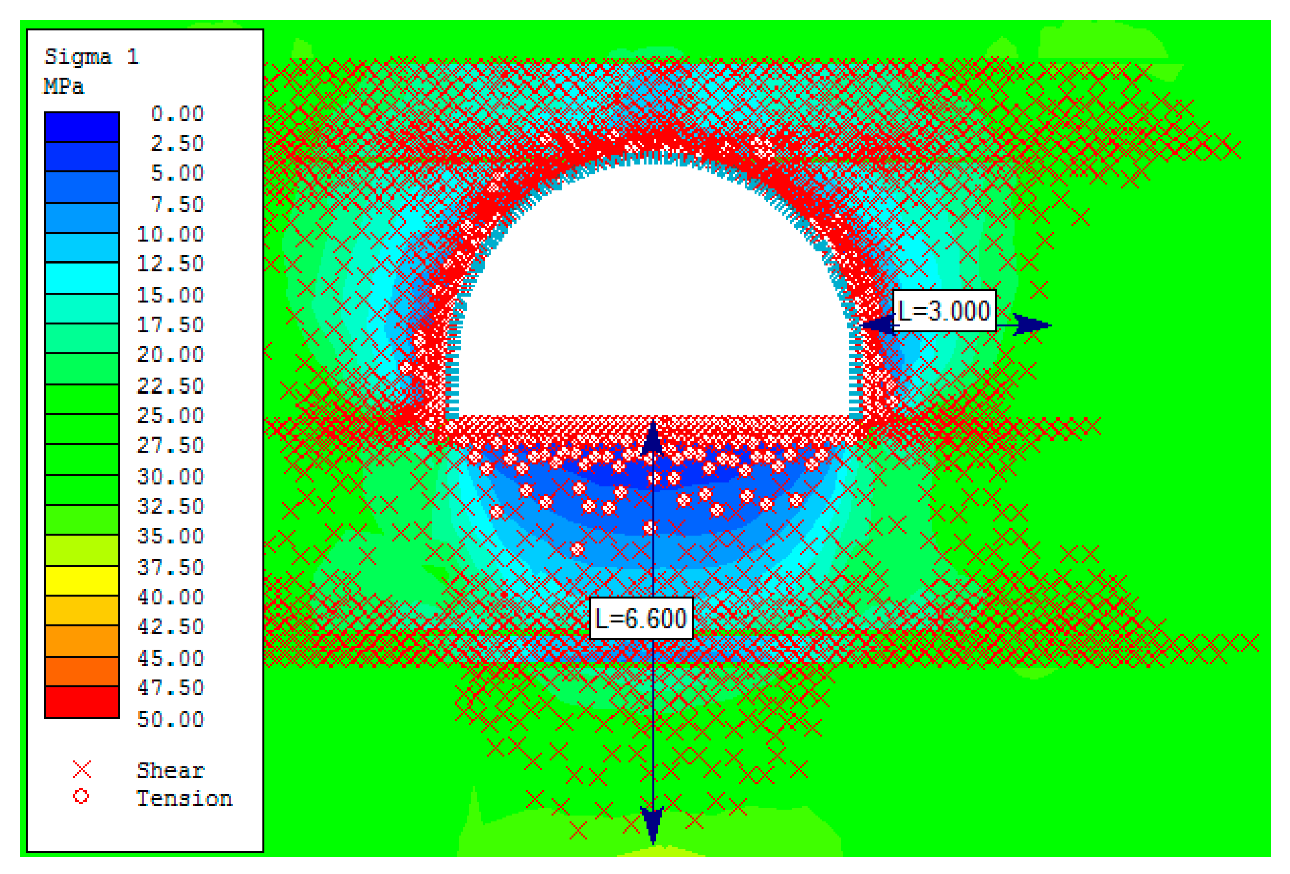
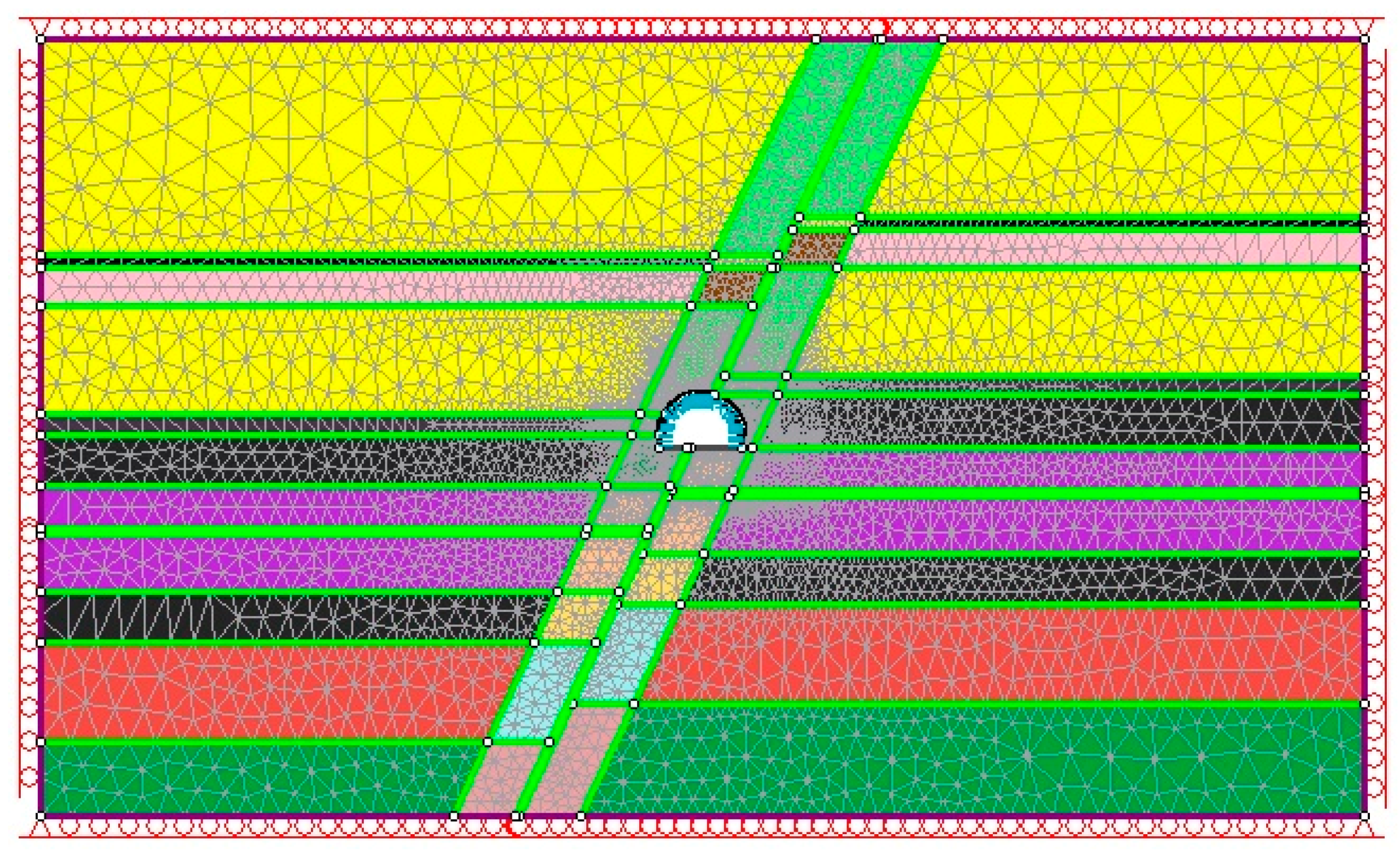
4. Numerical Evaluation of the Stability of the Opening
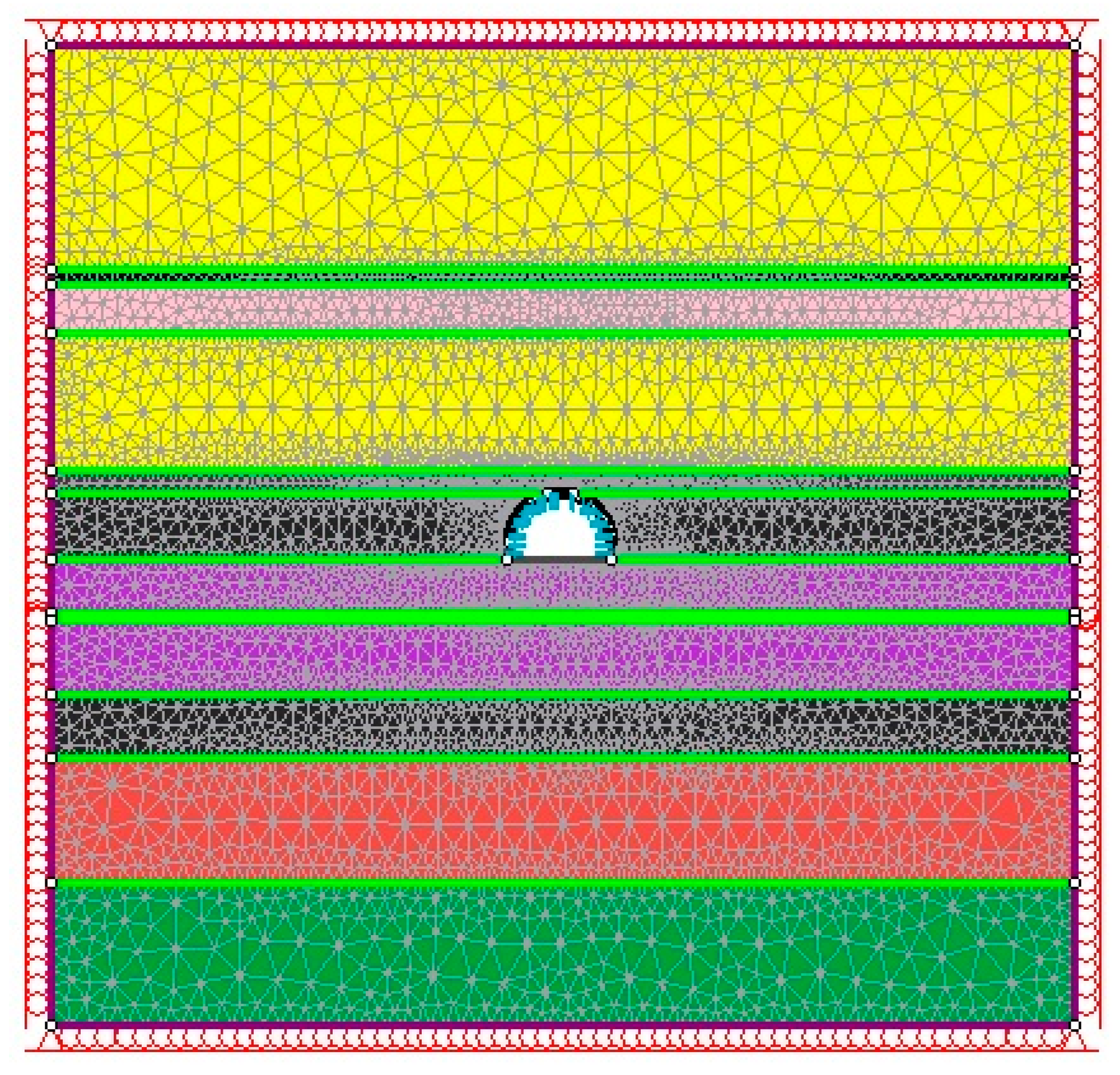
4.1. Assumptions of the Models
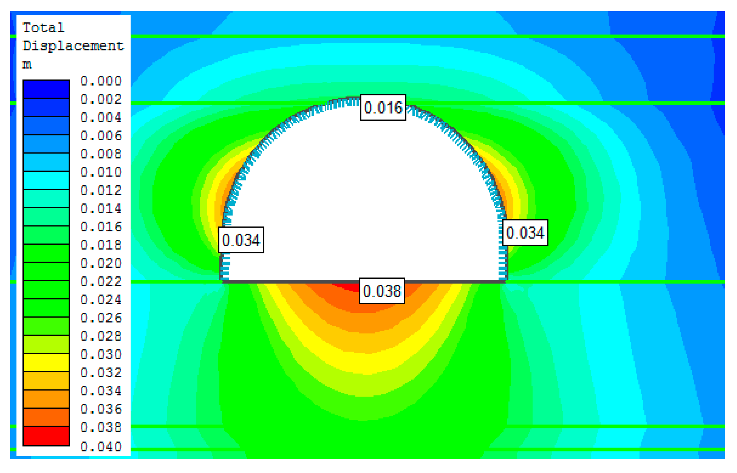
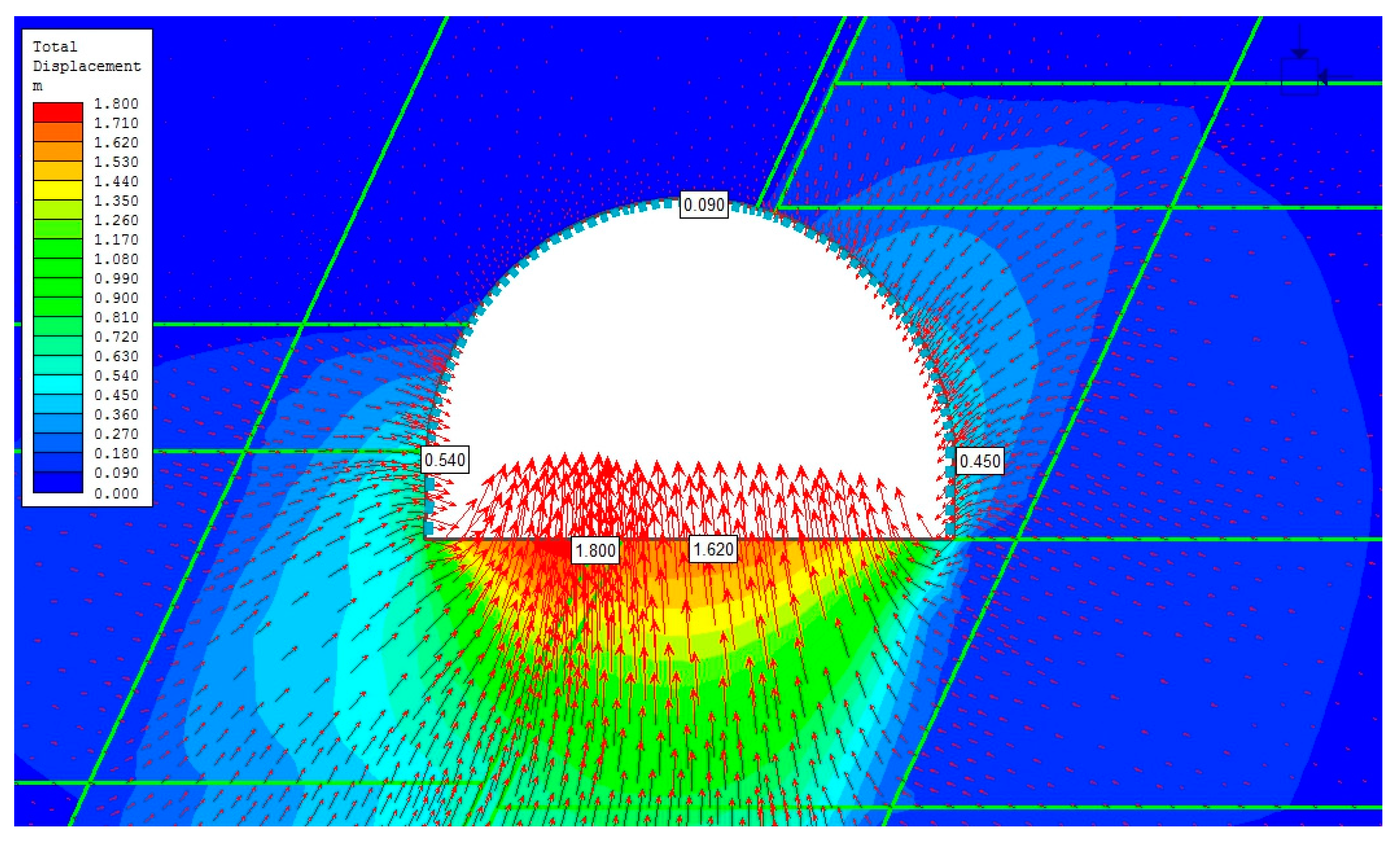
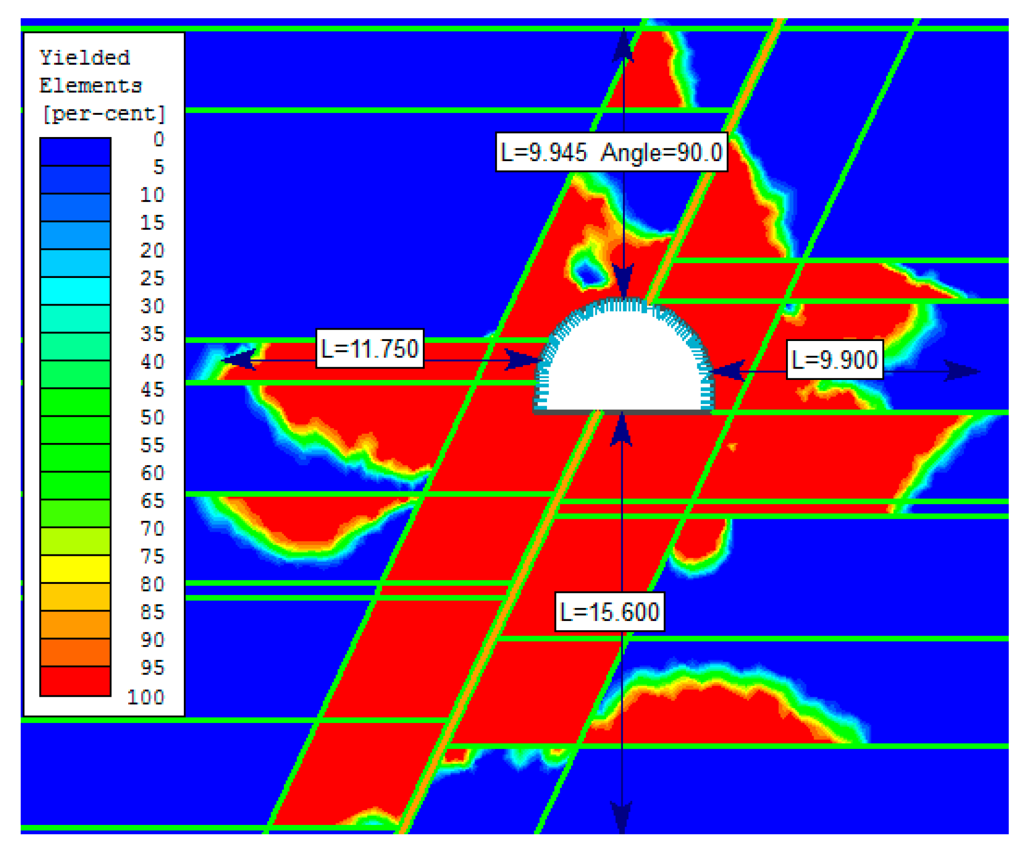
4.2. Section of the Roadway Unaffected by the Fault
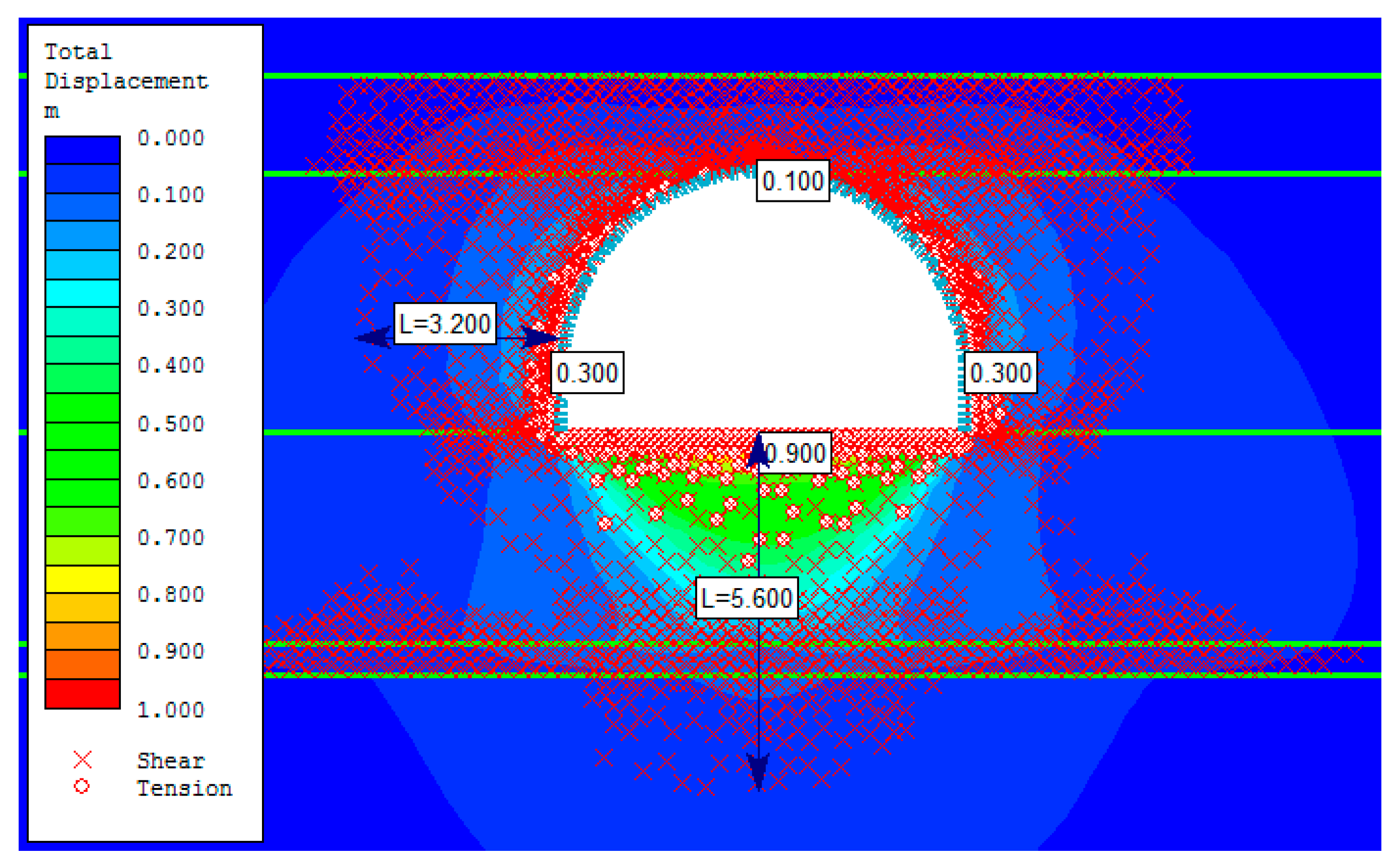
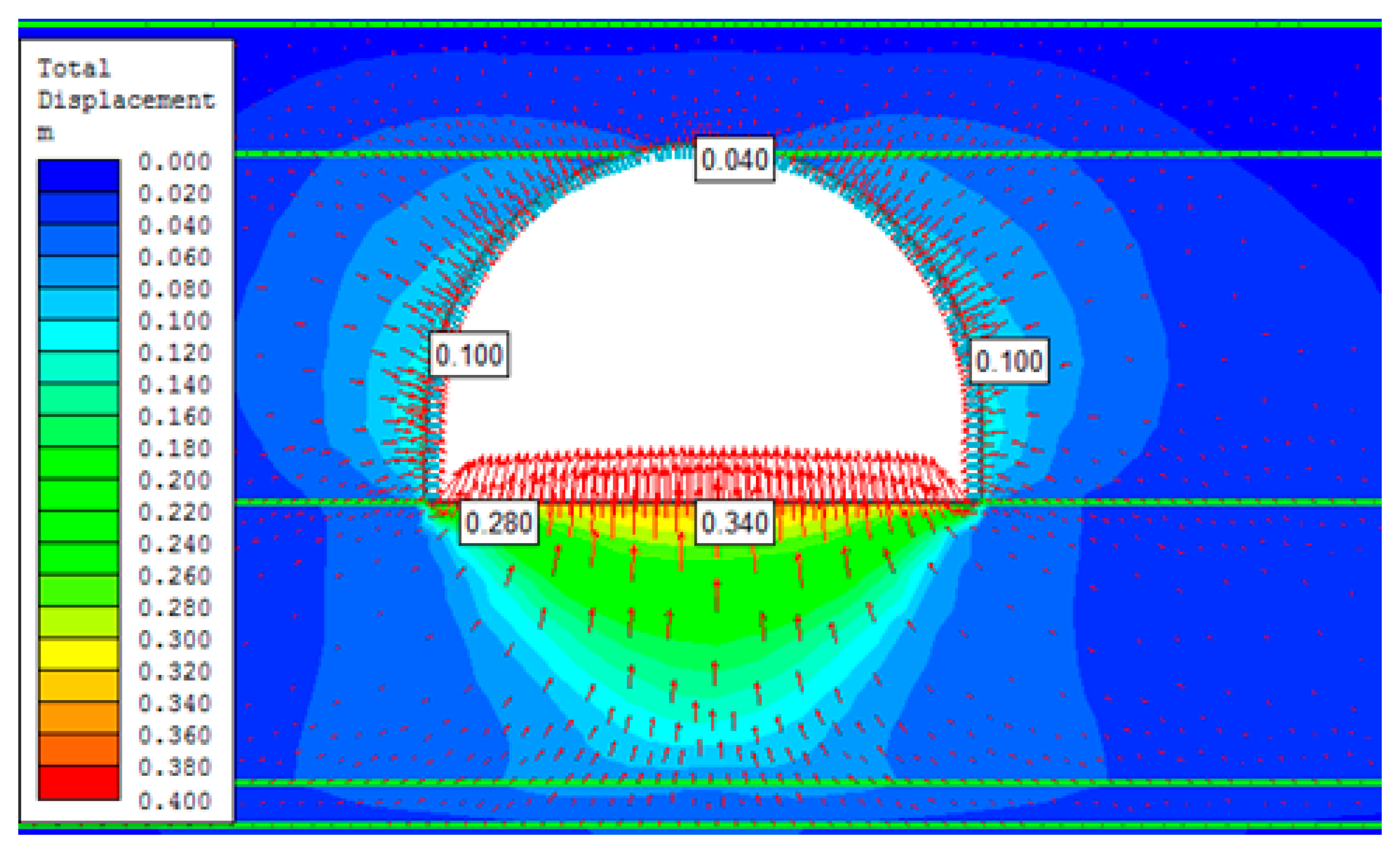
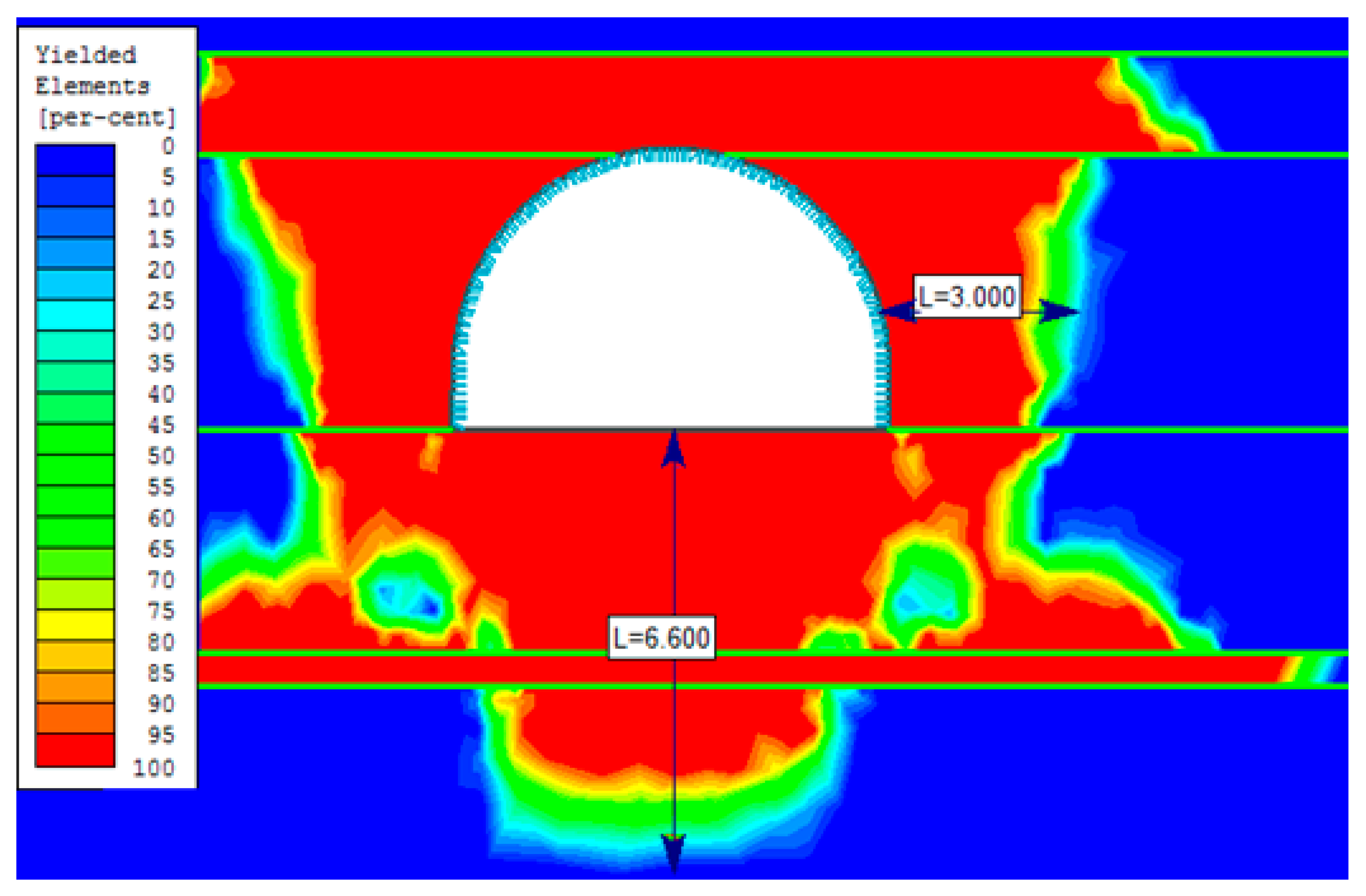
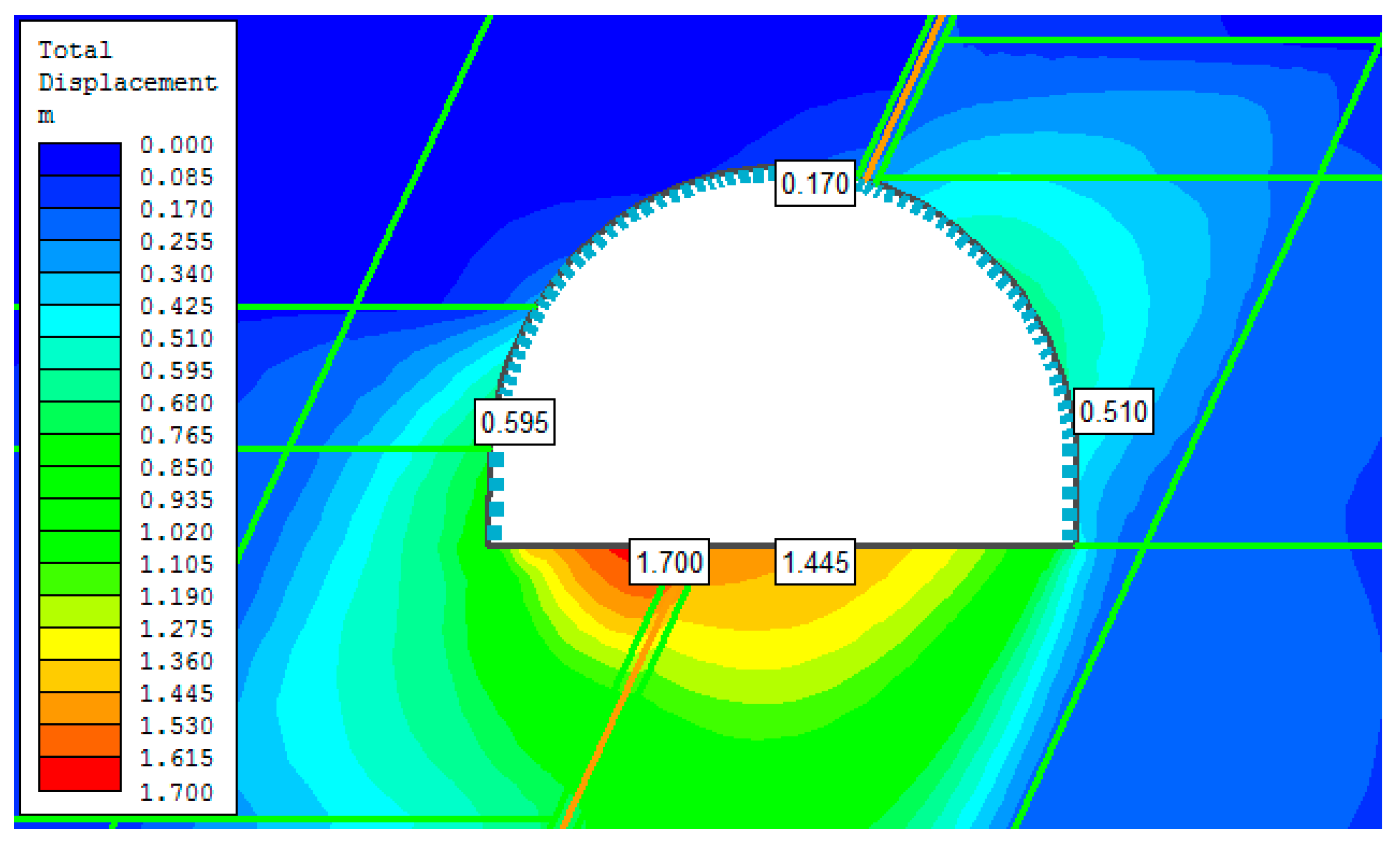
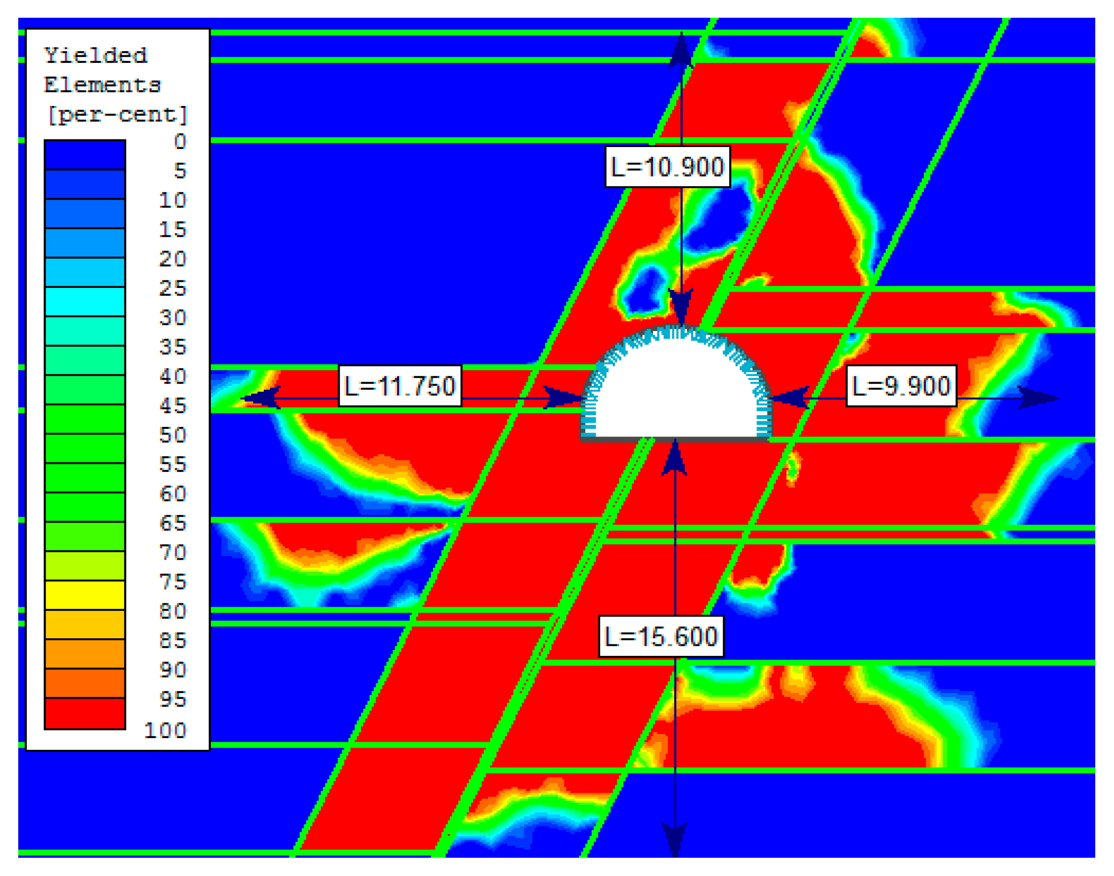
4.3. Section of the Roadway within the Fault Zone
5. Discussion
6. Conclusions
- The modelling of fault zones should be preceded by initial analysis of various physical models of the tectonically unaffected section, then a selection of the models that better reflect the rock mass condition in the investigated area.
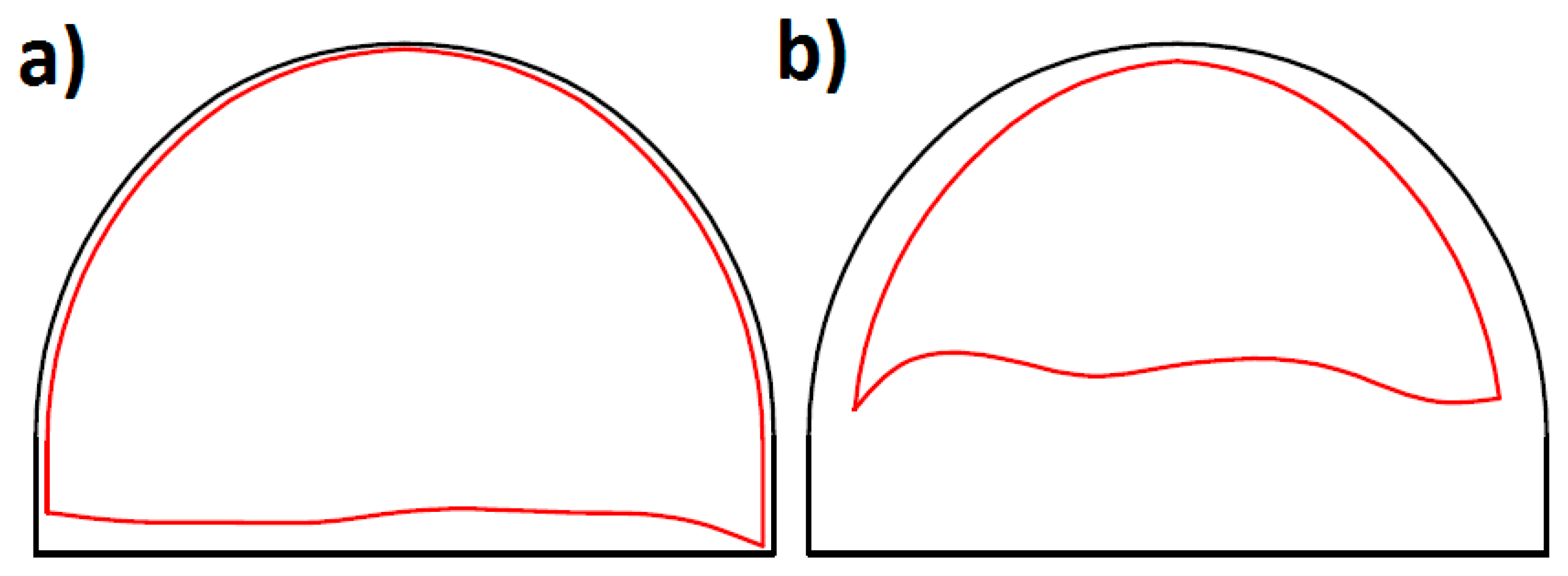
- In the case of the roadway section within a fault zone the extent of yielding of rock in the sidewalls is 3.5 times in average greater than in the section tectonically unaffected. In the instance of an investigated fault zone, which intersected the roadway at 65°, the extent of rock yielding in the roof reached two times the throw of the fault, in the floor 3 times the throw, and horizontally approx. 1.5 to 1.8 times the width of modelled fault zone. Noticeably, the extent of yielded rock mass in the fault section is asymmetrical and this asymmetry changes together with the fault throw and its inclination.
- All numerical models of deformations around mining roadway should be verified by in situ measurements in purpose to determine the applicability of physical model to existing geological and mining conditions and for the calibration of the models.
- The numerical analysis of the stability of the maingate D-2 pointed the selection of the adequate physical models and opened further prospects for modelling of mining roadways in faulted areas. However, the cases of mining roadways driven within the complicated set of the small throw faults of various positions and dips should be studied only with the help of 3D software packages.
Author Contributions
Conflicts of Interest
References
- Bukowska, M. The exploitation depth and bump hazard in the mines of the Upper Silesian Coal Basin. In Deep Mining Challenges, International Mining Forum 2009; CRC Press: London, UK, 2009; pp. 23–32. [Google Scholar] [CrossRef]
- Gao, J.; Zhao, W.; Lu, Y.; Zhai, J.; Yang, G. Control Mechanism and Countermeasures for the Stability of Roadway Surrounding Rock in Fault Fracture Zone. China Univ. Min. Technol. 2014, 19, 10685–10698. [Google Scholar]
- Kidybiński, A. Podstawy Geotechniki Kopalnianej; Wydawnictwo Śląsk: Katowice, Poland, 1982. (In Polish) [Google Scholar]
- Nieć, M. Geologia Kopalniana; Wydawnictwo Geologiczne: Warszawa, Poland, 1990. (In Polish) [Google Scholar]
- Shen, H.C.; Cheng, Y.F.; Wang, J.Y. Finite element study on the effects of faults on the ground stress field. Pet. Geol. Oilfield Dev. Daqing 2007, 4, 34–37. [Google Scholar]
- Su, Y.; Zhang, M.; Zhang, Z. The Influence of Large Fault on Tunnels in Underground Mines. Electron. J. Geotech. Eng. 2017, 22, 3397–3402. [Google Scholar]
- Wang, H.; Jiang, Y.; Xue, S.; Mao, L.; Lin, Z.; Deng, D.; Zhang, D. Influence of fault slip on mining-induced pressure and optimization of roadway support design in fault-influenced zone. J. Rock Mech. Geotech. Eng. 2016, 8, 660–671. [Google Scholar] [CrossRef]
- Yan, S.; Bai, J.; Li, W.; Chen, J.; Li, L. Deformation mechanism and stability control of roadway along a fault subjected to mining. Int. J. Min. Sci. Technol. 2012, 22, 559–565. [Google Scholar] [CrossRef]
- Yao, Q.; Li, X.; Pan, F.; Wang, T.; Wang, G. Deformation and Failure Mechanism of Roadway Sensitive to Stress Disturbance and Its Zonal Support Technology. Shock Vib. 2016, 2016, 1812768. [Google Scholar] [CrossRef]
- Małkowski, P.; Ostrowski, Ł.; Bachanek, P. The impact of the low throw fault on the stability of roadways in a hard coal mine. Stud. Geotech. Mech. 2017, 39, 63–72. [Google Scholar] [CrossRef]
- Xi, X.; Guo, Q.; Liu, T.; Yan, Z. Comprehensive Monitoring and Stability Assessment of Roadway with Water Gushing in a Fault Zone. Electron. J. Geotech. Eng. 2015, 20, 3895–3901. [Google Scholar]
- Brodny, J. Analysis of operation of new construction of the frictional joint with the resistance wedge. Arch. Min. Sci. 2012, 57, 209–227. [Google Scholar]
- Central Mining Institute. Simplified Principles of Standing Support Designing for the Headings Driven in Hard Coal Mines; Series Instructions No. 15; Central Mining Institute: Katowice, Poland, 2001. (In Polish) [Google Scholar]
- Silesian Technical University. The Principles of Standing Support Designing for the Headings Driven in Hard Coal Mines, 2nd ed.; Corrected; Institute for the Exploitation of Deposits, Silesian TU: Gliwice, Poland, 2000. (In Polish) [Google Scholar]
- Borynia,-Zofiówka-Jastrzębie Hard Coal Mine. Technical Documentation of Maingate D-2, Unpublished work. 2014. (In Polish)
- Małkowski, P.; Niedbalski, Z.; Majcherczyk, T. Investigations of Hard Coal Mine Roadways Stability in Stratified Rock. In Proceedings of the 8th International Symposium on Ground Support in Mining and Underground Construction: Ground Support 2016, Lulea, Sweden, 12–14 September 2016. [Google Scholar]
- Yu, W.; Wang, W.; Chen, X.; Du, S. Field investigations of high stress soft surrounding rocks and deformation control. Int. J. Rock Mech. Min. Sci. 2015, 7, 421–433. [Google Scholar] [CrossRef]
- Prusek, S. Empirical-statistical model of gateroads deformation. Arch. Min. Sci. 2010, 55, 295–312. [Google Scholar]
- Małkowski, P. The impact of the physical model selection and rock mass stratification on the results of numerical calculations of the state of rock mass deformation around the roadways. Tunn. Undergr. Space Technol. 2015, 50, 365–375. [Google Scholar] [CrossRef]
- Hoek, E.; Diederichs, M.S. Empirical estimation of rock mass modulus. Int. J. Rock Mech. Min. Sci. 2006, 43, 203–215. [Google Scholar] [CrossRef]
- Bieniawski, Z.T. Determining rock mass deformability: Experience from cases histories. Int. J. Rock Mech. Min. Sci. 1978, 15, 237–247. [Google Scholar] [CrossRef]
- Dinc, O.S.; Sonmez, H.; Tunusluoglu, C.; Kasapoglu, K.E. A new general empirical approach for the prediction of rock mass strength of soft to hard rock masses. Int. J. Rock Mech. Min. Sci. 2011, 48, 650–665. [Google Scholar] [CrossRef]
- Małkowski, P. Behavior of joint in sandstones during the shear test. Acta Geodyn. Geomater. 2015, 12, 399–410. [Google Scholar]
- Pilecki, Z. Modelowanie numeryczne pola naprężenia w górotworze naruszonym wielopokładową eksploatacją węgla kamiennego w warunkach silnego zagrożenia sejsmicznego. Zeszyty Naukowe Instytutu Gospodarki Surowcami Mineralnymi i Energią PAN 2011, 80, 93–102. (In Polish) [Google Scholar]
- Prusek, S.; Walentek, A. Ocena zmian zachodzących w górotworze w bezpośrednim otoczeniu ściany. Wiadomości Górnicze 2015, 12, 610–622. (In Polish) [Google Scholar]


| Spacing | V-Shape Height | V-Shape Cross Section Area | V-Shape Moment of Inertia | Steel Young Modulus | Steel Poisson Ratio | Steel Yield Limit | Steel Tensile Strength |
|---|---|---|---|---|---|---|---|
| [m] | [m] | [m2] | [m4] | [GPa] | [-] | [MPa] | [MPa] |
| 0.6 | 0.171 | 0.004083 | 8.38 × 10⁻⁶ | 210 | 0.3 | 480 | 650 |
| Mointoring Station Chainage | Measured Results | ||||||||
|---|---|---|---|---|---|---|---|---|---|
| Change of Width of the Roadway | Change of Height of the Roadway | Floor Heave | Change of the Roadway Cross-Section | ||||||
| ΔW [cm] | ΔW [%] | ΔH [cm] | ΔH [%] | ufl min [cm] | ufl max [cm] | ufl av [cm] | ΔA [m2] | ΔA [%] | |
| 930 m | 20 | 3.3 | 38.5 | 9.1 | 5.7 | 35.1 | 25.8 | 2.87 | 13.3 |
| 757 m | 73 | 12.0 | 167.5 | 39.6 | 118 | 180.5 | 148.1 | 11.67 | 54.2 |
| Stratum | Rock Type | Thickness | Specific Weight | UCS | Young Modulus (Lab. Test) | Young Modulus (Rock Mass) | Poisson Ratio | Hoek Brown Failure Criteria | |
|---|---|---|---|---|---|---|---|---|---|
| h [m] | γ [kN/m3] | Rc [MPa] | Ei [GPa] | Em [GPa] | ν [-] | ms | s | ||
| Fault | Breccia | 0.3 | 20 | 8.0 | 0.75 | - | 0.35 | 0.240 | 0.00008 |
| Roof | Sandstone | 16.9 | 25.32 | 80.8 | 10.78 | 6.24 | 0.29 | 2.851 | 0.0039 |
| Coal bed 411/3 | 1.0 | 13.02 | 10.2 | 1.57 | 0.90 | 0.30 | 1.729 | 0.0008 | |
| Mudstone | 3.0 | 25.01 | 41.2 | 6.98 | 1.67 | 0.32 | 0.937 | 0.0031 | |
| Sandstone | 8.5 | 25.32 | 80.8 | 10.78 | 6.24 | 0.29 | 2.851 | 0.0039 | |
| Coaly shale | 1.5 | 24.43 | 33.8 | 5.62 | 0.80 | 0.35 | 0.475 | 0.0004 | |
| Sidewall | Coal bed 412 | 4.1 | 12.81 | 12.4 | 1.86 | 0.90 | 0.3 | 1.729 | 0.0008 |
| Floor | Claystone | 3.3 | 24.97 | 50.3 | 4.55 | 1.60 | 0.28 | 0.906 | 0.00011 |
| Coal | 0.5 | 12.50 | 8.1 | 2.02 | 0.90 | 0.3 | 1.233 | 0.0002 | |
| Claystone | 4.5 | 26.33 | 61.3 | 8.19 | 1.60 | 0.31 | 0.906 | 0.00011 | |
| Coal bed 413 | 4 | 12.48 | 11.9 | 1.69 | 0.90 | 0.3 | 1.729 | 0.0008 | |
| Mudstone | 7.7 | 26.33 | 61.3 | 8.19 | 5.8 | 0.31 | 2.677 | 0.0094 | |
| Claystone | 6 | 26.73 | 50.2 | 6.23 | 1.67 | 0.29 | 0.937 | 0.0031 | |
| No. | Physical Model (Isotropic) | Young Modulus E | Post-Failure Strength Change | Support | Support Frame Slide Possible | Contact between Strata |
|---|---|---|---|---|---|---|
| 1 | Elasto-plastic | Laboratory | - | Yes, steel yielding support | No | material boundary |
| 2 | Elasto-plastic | Laboratory | - | Yes, steel yielding support | Yes; 0.5% | material boundary |
| 3 | Elasto-plastic | Rock mass | - | Yes, steel yielding support | No | material boundary |
| 4 | Elasto-plastic | Laboratory | - | No | - | material boundary |
| 5 | Elasto-plastic | Laboratory | +20% | Yes, steel yielding support | No | material boundary |
| 6 | Elasto-plastic | Laboratory | −20% | Yes, steel yielding support | No | material boundary |
| 7 | Elasto-plastic | Laboratory | - | Yes, steel yielding support | No | joint type case 1 |
| 8 | Elasto-plastic | Laboratory | - | Yes, steel yielding support | No | joint type case 2 |
| 9 | Elasto-plastic | Laboratory | - | Yes, steel yielding support | No | joint type case 3 |
| 10 | Elastic | Laboratory | - | Yes, steel yielding support | No | material boundary |
| 11 | Elastic | Laboratory | - | Yes, steel yielding support | Yes; 0.5% | material boundary |
| 12 | Elastic | Rock mass | - | Yes, steel yielding support | No | material boundary |
| 13 | Elastic | Laboratory | - | No | - | material boundary |
| Model | Δurf [cm] | Δufl [cm] | ΔH [cm] | ΔW [cm] | Conformity |
|---|---|---|---|---|---|
| 1 | 4 | 34 | 38 | 20 | 96.90% |
| 2 | 20 | 32 | 52 | 48 | 43.78% |
| 3 | 10 | 90 | 100 | 60 | 38.22% |
| 4 | 32.5 | 40 | 72.5 | 50 | 31.29% |
| 5 | 3 | 22.5 | 25.5 | 21 | 73.52% |
| 6 | 5 | 40 | 45 | 30 | 80.70% |
| 7 | 4 | 32 | 36 | 24 | 89.13% |
| 8 | 4 | 38 | 42 | 24 | 87.01% |
| 9 | 25 | 45 | 70 | 35 | 38.29% |
| 10 | 1.6 | 3.8 | 5.4 | 6.8 | 23.69% |
| 11 | 2 | 4.3 | 8.6 | 48 | 9.86% |
| 12 | 4 | 9.5 | 13.5 | 12 | 52.97% |
| 13 | 2 | 4.3 | 6.3 | 8.6 | 29.11% |
| Measured values | 4.5 | 34 | 38.5 | 20 | - |
| Model No. | Isotropic Model | Young Modulus E | Post-Failure Strength Change | Support | Support Frame Slide Possible | Contact of the Beds on Fault Plane |
|---|---|---|---|---|---|---|
| 1 | Elasto-plastic | Laboratory | - | Yes, steel yielding support | Yes; 0.5% | material boundary |
| 2 | Elasto-plastic | Laboratory | - | Yes, steel yielding support | No | material boundary |
| 3 | Elasto-plastic | Laboratory | –20% | Yes, steel yielding support | No | material boundary |
| 4 | Elasto-plastic | Laboratory | –20% | Yes, steel yielding support | Yes; 0.5% | material boundary |
| 5 | Elasto-plastic | Laboratory | –20% | Yes, steel yielding support | No | joint type case 4 |
| 6 | Elasto-plastic | Laboratory | –20% | Yes, steel yielding support | Yes; 0.5% | joint type case 4 |
| 7 | Elasto-plastic | Laboratory | –20% | Yes, steel yielding support | No | joint type case 5 |
| 8 | Elasto-plastic | Laboratory | –20% | Yes, steel yielding support | Yes; 0.5% | joint type case 5 |
| Model | Δufl Max | Δufl | Δurf | ΔH Δurf + Δufl | ΔW | Average Conformity | ||
|---|---|---|---|---|---|---|---|---|
| Left | Right | L + R | ||||||
| [cm] | [-] | |||||||
| 1 | 133 | 119 | 14 | 133 | 63 | 42 | 105 | 75.42% |
| 2 | 142.5 | 127.5 | 7.5 | 135 | 45 | 37.5 | 82.5 | 75.01% |
| 3 | 180 | 162 | 9 | 171 | 54 | 45 | 99 | 72.60% |
| 4 | 170 | 153 | 17 | 170 | 76.5 | 51 | 127.5 | 76.45% |
| 5 | 161.5 | 144.5 | 8.5 | 153 | 42.5 | 42.5 | 85 | 81.25% |
| 6 | 152 | 136 | 16 | 152 | 64 | 48 | 112 | 78.46% |
| 7 | 171 | 153 | 9 | 162 | 36 | 45 | 81 | 85.85% |
| 8 | 170 | 144.5 | 17 | 161.5 | 59.5 | 51 | 110.5 | 81.20% |
| Measured values | 180 | 152 | 15 | 168 | - | 73 | - | |
© 2017 by the authors. Licensee MDPI, Basel, Switzerland. This article is an open access article distributed under the terms and conditions of the Creative Commons Attribution (CC BY) license (http://creativecommons.org/licenses/by/4.0/).
Share and Cite
Piotr, M.; Łukasz, O.; Piotr, B. Modelling the Small Throw Fault Effect on the Stability of a Mining Roadway and Its Verification by In Situ Investigation. Energies 2017, 10, 2082. https://doi.org/10.3390/en10122082
Piotr M, Łukasz O, Piotr B. Modelling the Small Throw Fault Effect on the Stability of a Mining Roadway and Its Verification by In Situ Investigation. Energies. 2017; 10(12):2082. https://doi.org/10.3390/en10122082
Chicago/Turabian StylePiotr, Małkowski, Ostrowski Łukasz, and Bachanek Piotr. 2017. "Modelling the Small Throw Fault Effect on the Stability of a Mining Roadway and Its Verification by In Situ Investigation" Energies 10, no. 12: 2082. https://doi.org/10.3390/en10122082
APA StylePiotr, M., Łukasz, O., & Piotr, B. (2017). Modelling the Small Throw Fault Effect on the Stability of a Mining Roadway and Its Verification by In Situ Investigation. Energies, 10(12), 2082. https://doi.org/10.3390/en10122082