
Characteristic Analysis and Fault-Tolerant Control of Circulating Current for Modular Multilevel Converters under Sub-Module Faults


Abstract
:1. Introduction
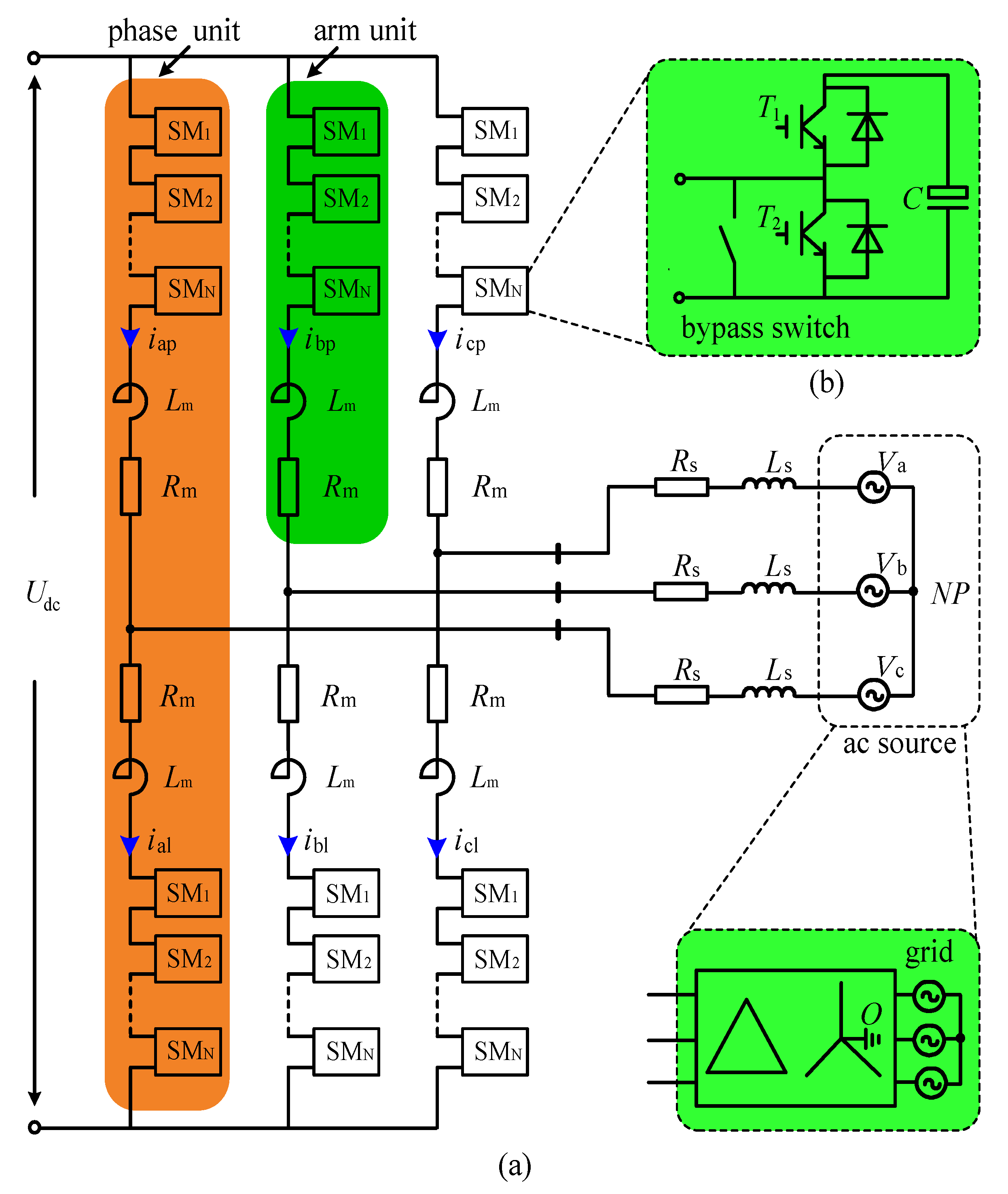
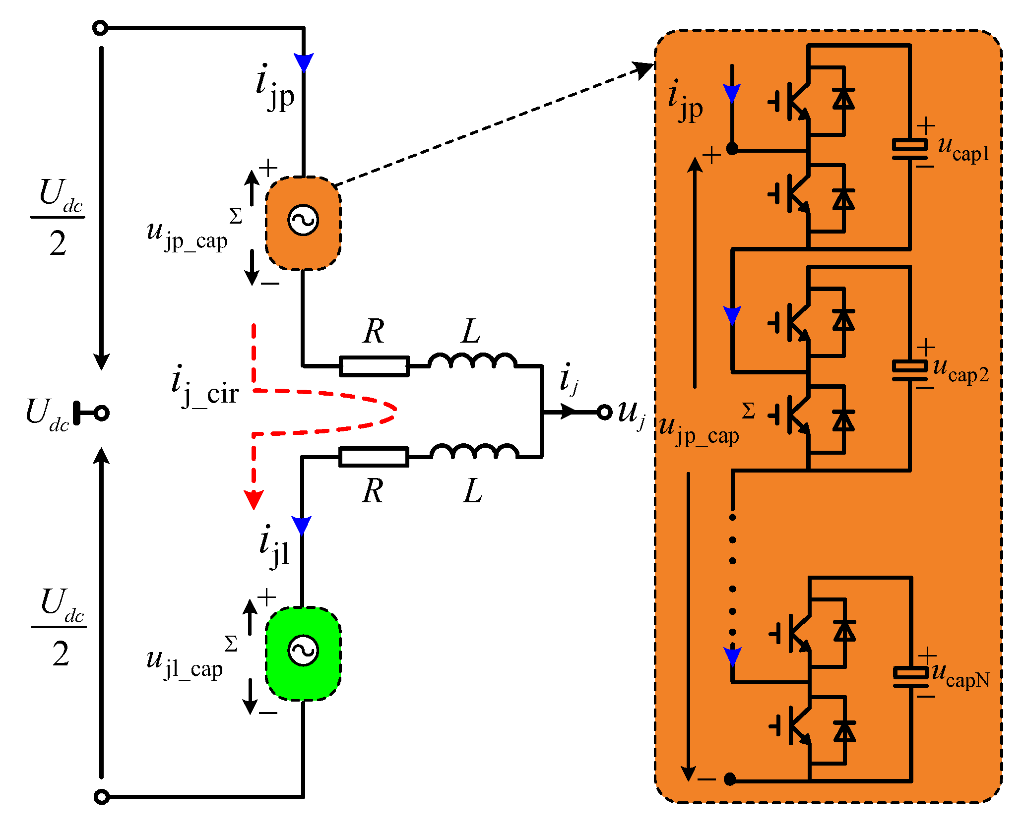
2. Basic Principles of MMC
3. Analysis of the Circulating Current Characteristic of MMC under SM Faults
3.1. Basic Matheatical Mode
3.2. Mathematical Mode under SM Faults
3.3. Summarizing of the Circulting Current Characteristic under SM Faults
- Three-phase with symmetrical fault, which means: Condition 1a, κa = κb = κc = 0; and Condition 1b, μa = μb = μc ≠ 0. The harmonic components of the circulating current in this fault situation are actually the same as the normal operation situation. It only consists of even-order frequency components, which are negative-sequence symmetrical. As the higher-order contents are very small, the twice frequency component is the mainly. This conclusion also can explain the main characteristics of the circulating current of MMC under the normal operation state, which is consistent with the conclusion in [17].
- Single-phase with symmetrical fault, which means: Condition 2a, the κa = κb = κc = 0; and Condition 2b, μa, μb, μc are not exactly equal (because the fault SMs cause the factor μ of the fault phase not equaling to the normal phase). In this fault situation, the harmonics of the circulating current are also only included by even-orders restricted by the Condition 2a, and the twice frequency component is the main part. However, owing to Condition 2b, the even-order frequency components will no longer be negative-sequenced symmetrically.
- Single-phase with asymmetrical fault, which means: Condition 3a, the κa, κb, κc are not exactly equal to 0 (because the different number of faulty SMs in the upper arm and the lower arm cause the factor κ of the fault phase not equaling 0); and Condition 3b, μa, μb, μc are not exactly equal. The odd-order harmonics will appear in the circulating current besides the even-order harmonics during this fault situation as the Condition 3a. In addition, the even-order frequency components will also no longer be negative-sequenced symmetrically owing to the Condition 3b. Similarly, the fundamental and twice frequency components are the main parts of the even- and odd-order frequency components, respectively.
- Multi-phase with symmetrical/asymmetrical fault. As analyzed previously, the conditions about κa, κb, κc and μa, μb, μc can be obtained in the same way at first. Then, the harmonic characteristics of the circulating current can be concluded based on the conditions. They are basically the same as the single-phase symmetrical/asymmetrical faults, which are not repeated here.
4. Fault-Tolerant Control of Circulating Current Suppressing Strategy for MMC
4.1. Anysis of the Nonideal PR Control Mode
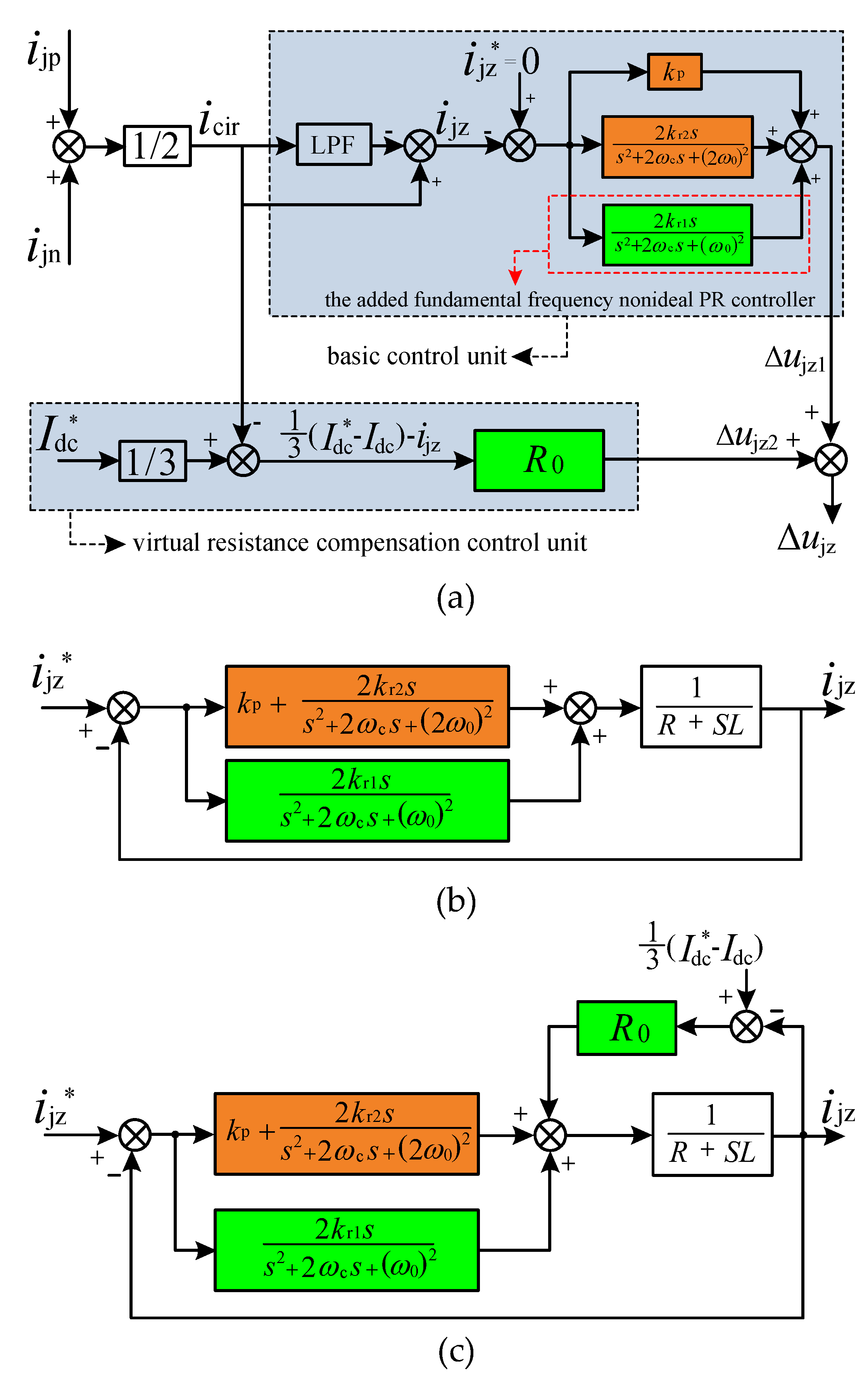
- During normal situations, a PR-based control strategy is often adopted in the traditional CCS control method [17,20,21]. It mainly has two modes, ideal PR and non-ideal PR. However, the ideal PR controller only tends to infinite magnitude at the resonant frequency, which will result in its performance being greatly reduced when the grid frequency fluctuates. Therefore, most PR controllers consider adopting a non-ideal PR control mode since it can reduce the sensibility to the frequency deviation. The transfer function of a non-ideal PR controller can be expressed as:where kp, kr, ωc, and ω0 are the proportional gain, resonant gain, cutoff frequency, and resonant frequency, respectively.
- Compared to the fault-tolerant control method based on a PI controller [13], the suppressing strategy based on a PR controller can achieve the independent control of each phase. In addition, it can avoid the acb-dq decoupling control. This would ensure the control effect when the three-phase alternative circulating currents appear asymmetrical. Meanwhile, it reduces the positive-, negative-, and zero-sequence controllers, which is more concise.
- Furthermore, in order to achieve the suppression for the fundamental frequency component, it only needs to introduce a fundamental frequency resonant controller into the traditional PR control system, which can reduce the design burden of the whole control system.
4.2. Fault-Tolerant Controller Design
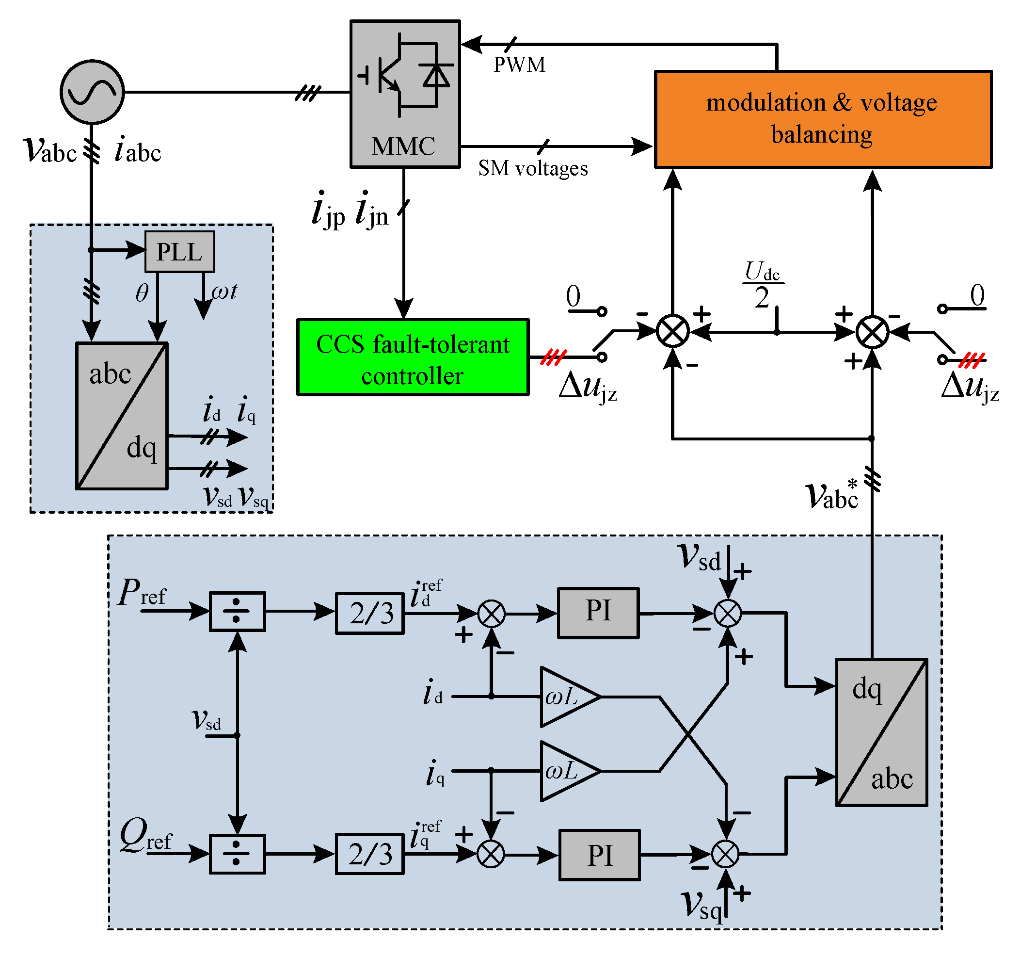
4.3. System Control Structure
5. Simulation Results
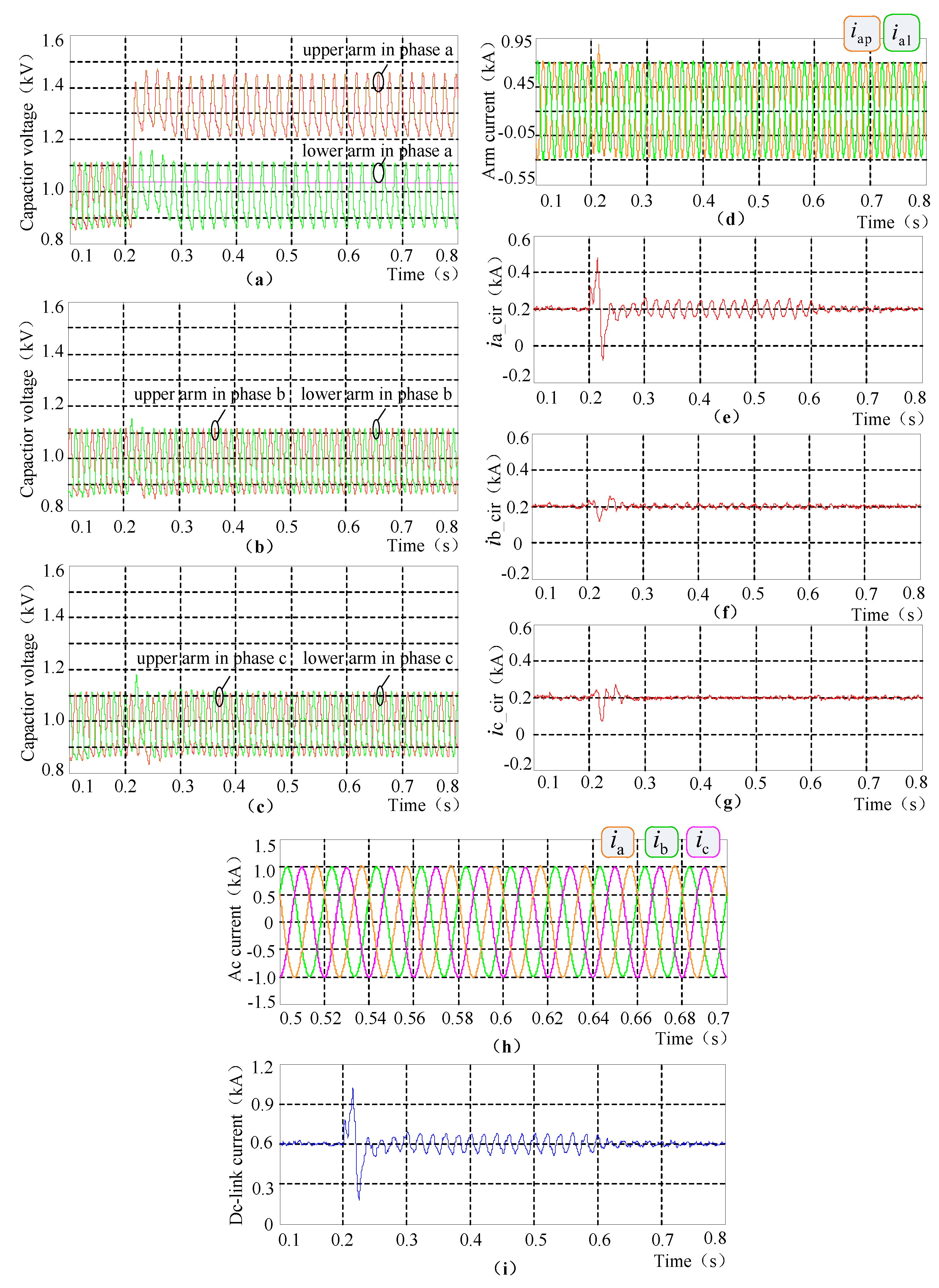
5.1. Case 1
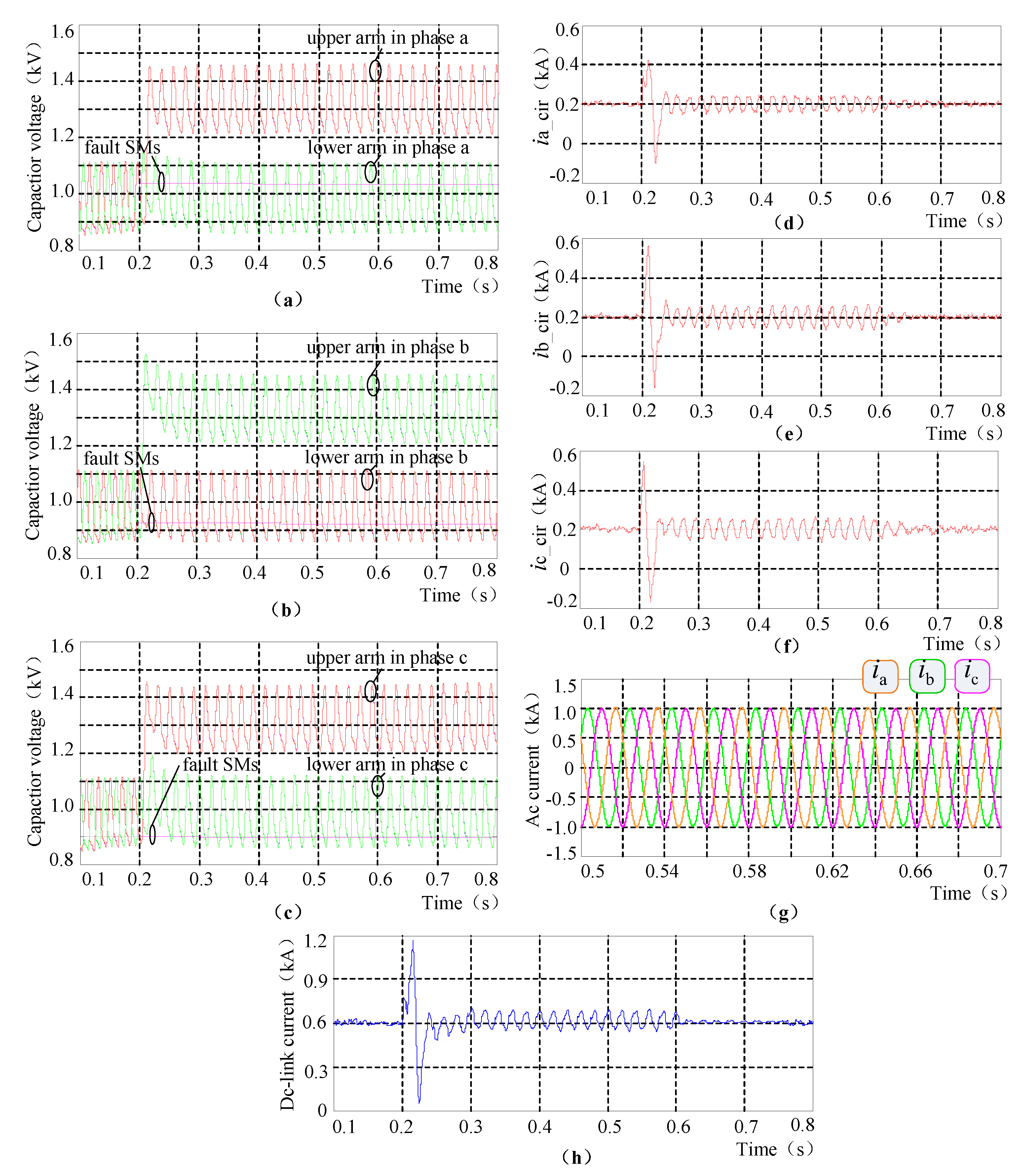
5.2. Case 2
5.3. Case 3
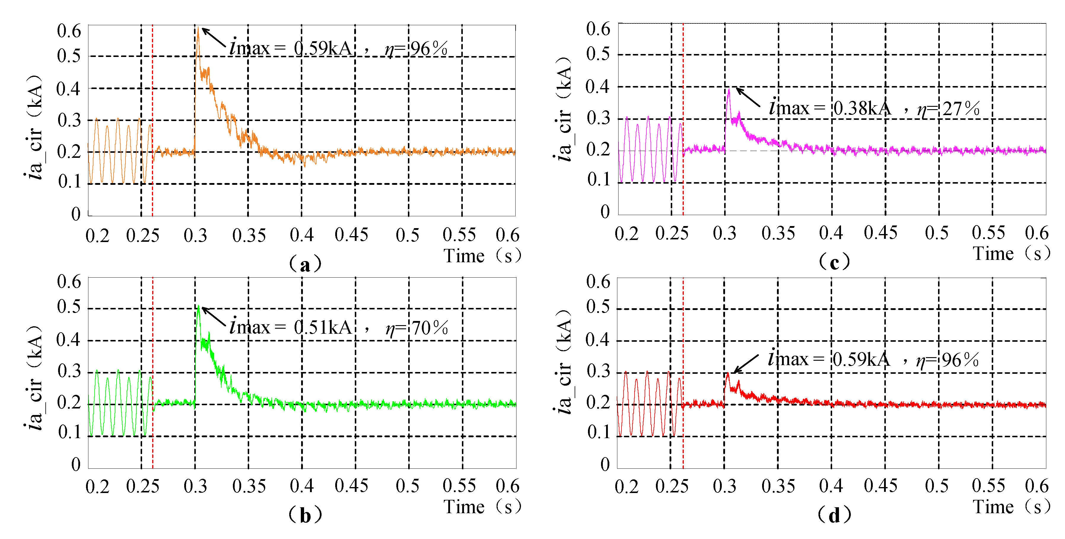
5.4. Case 4
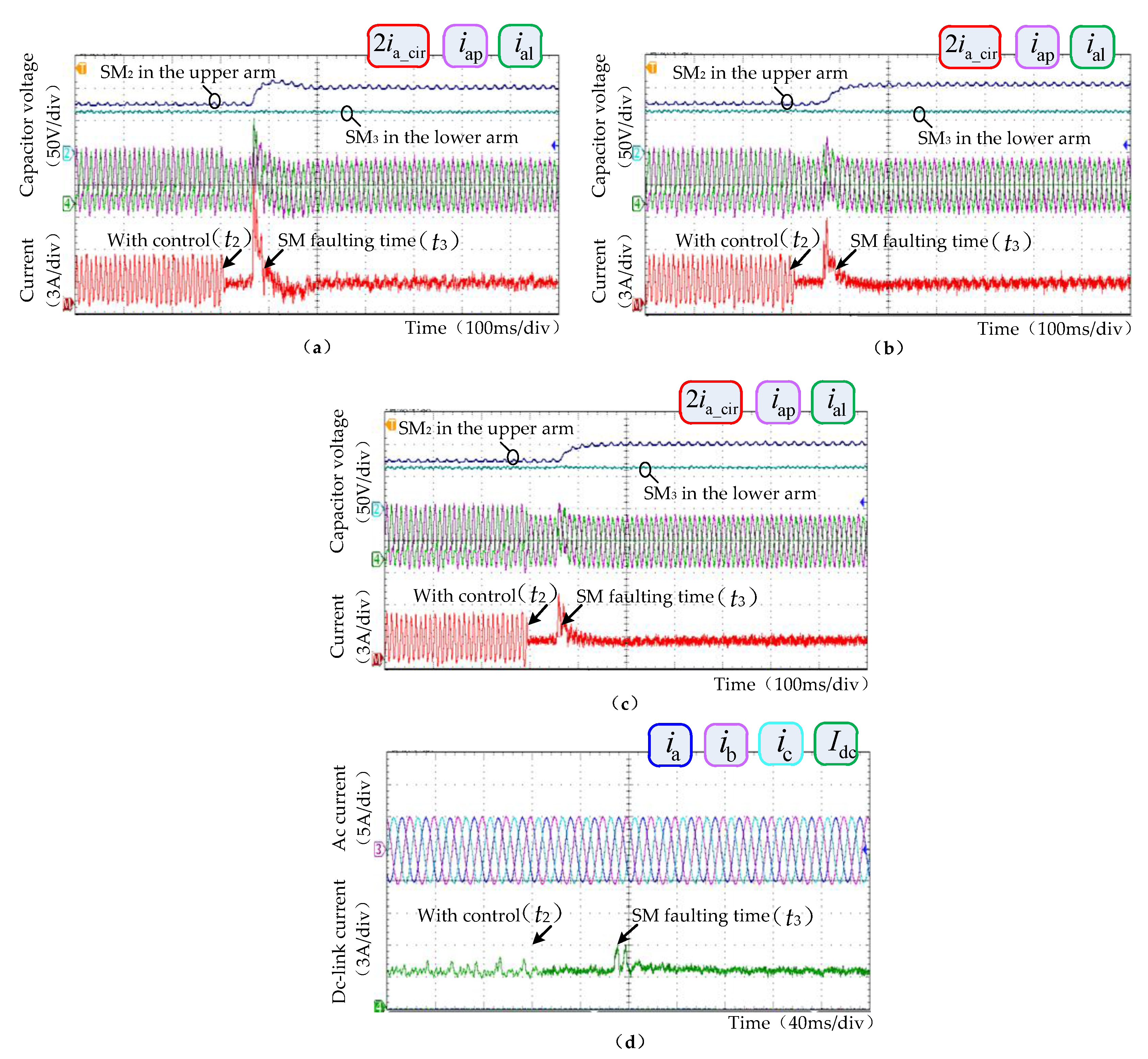
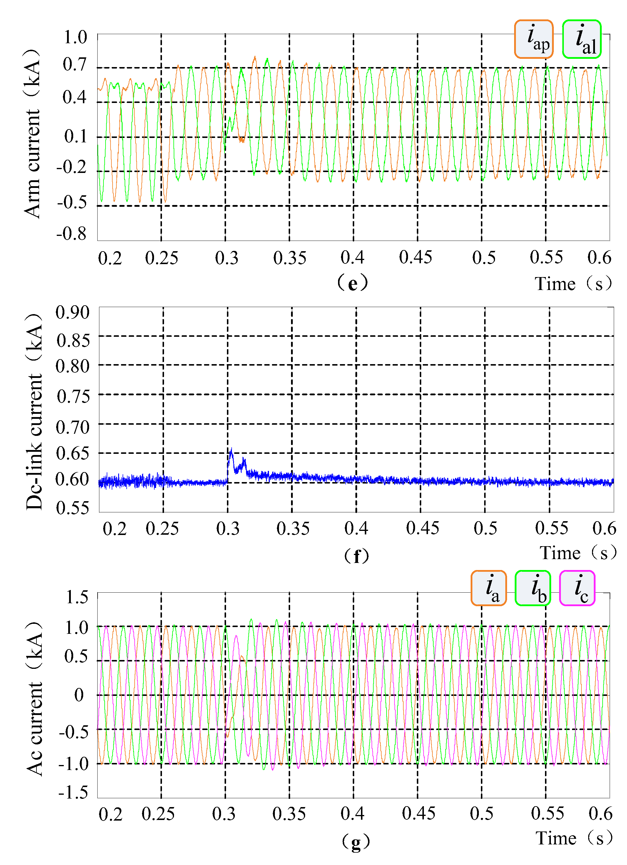
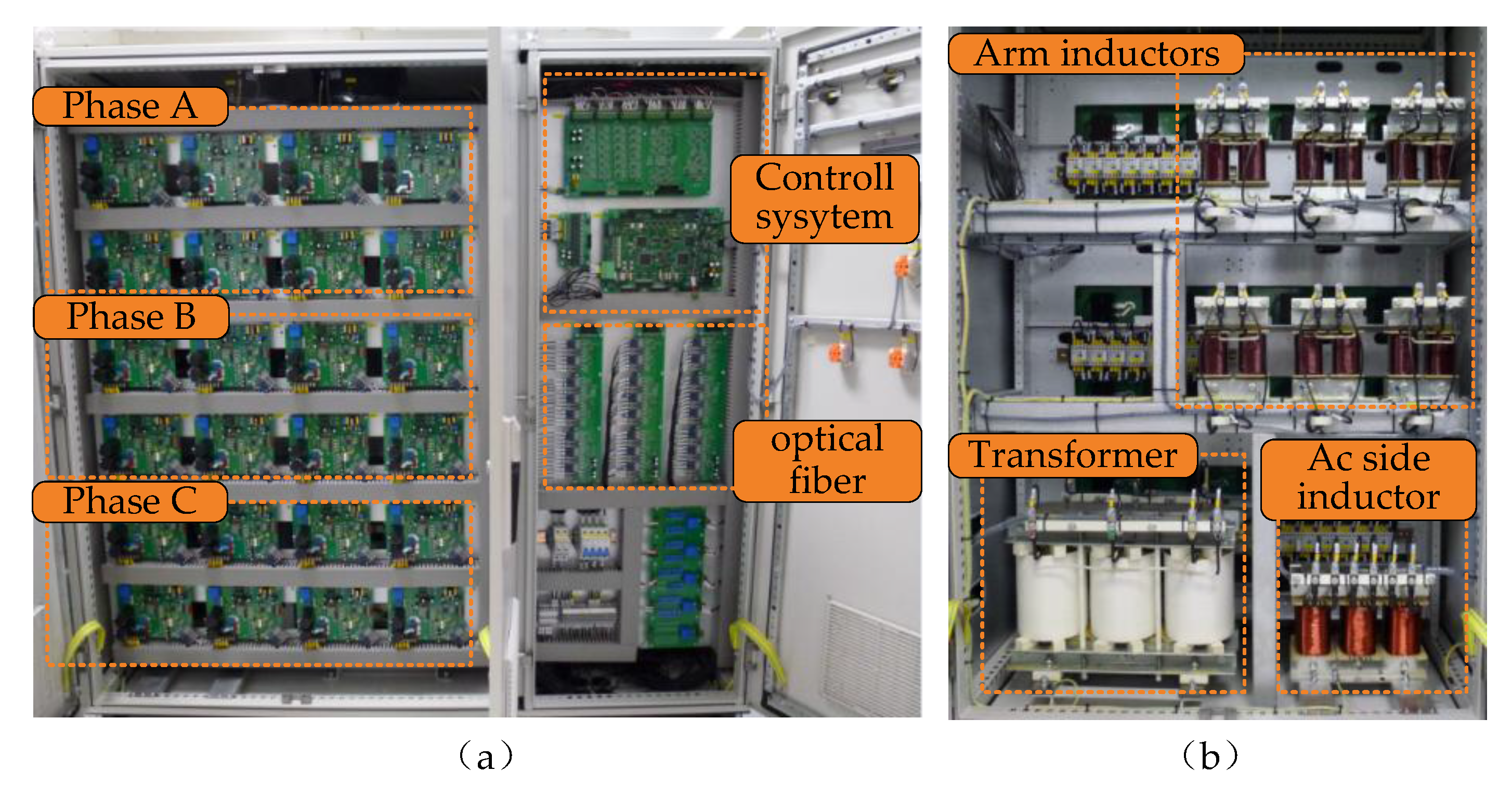
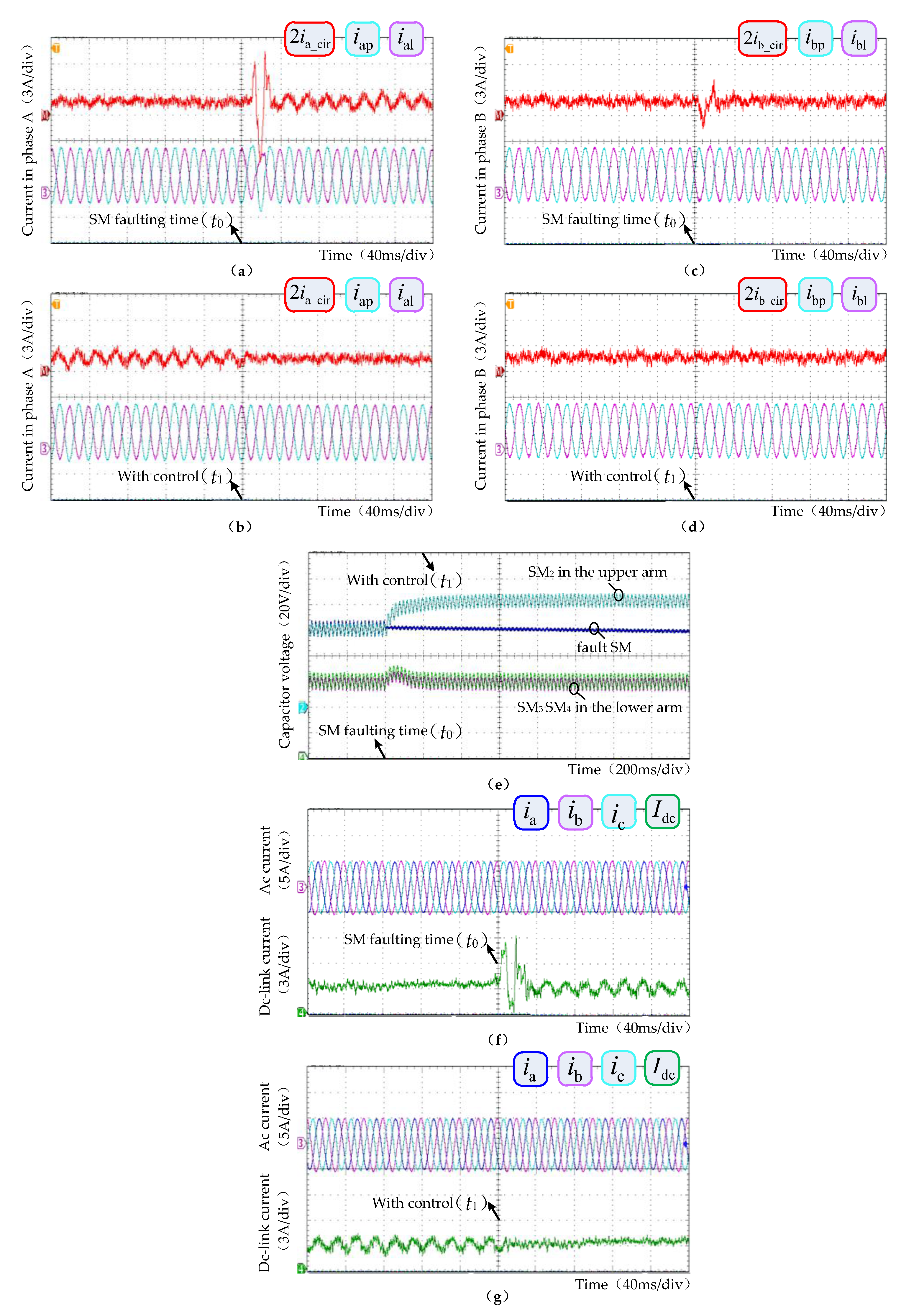
6. Experiments
6.1. Case 1
6.2. Case 2
7. Conclusions
- (1)
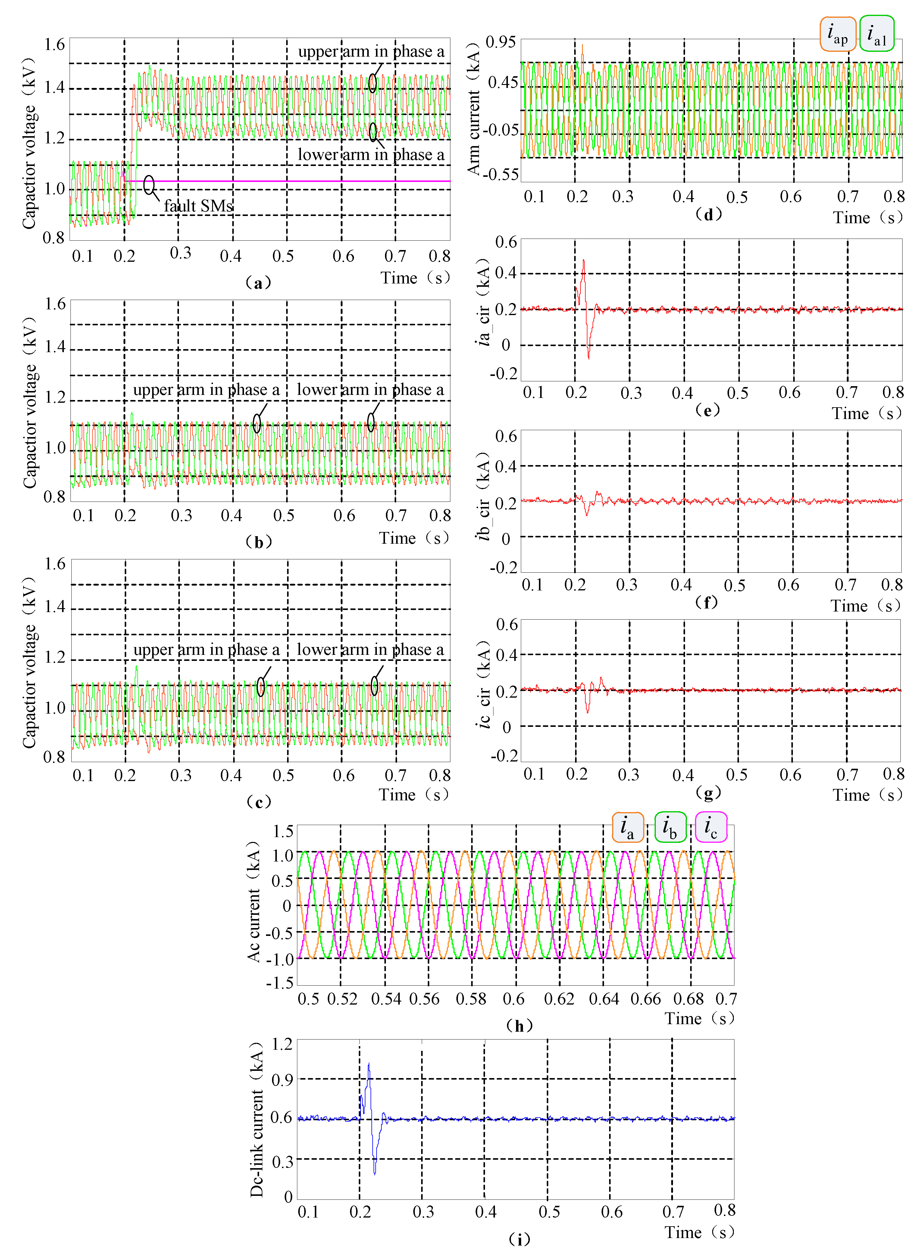
- The operation characteristics of the MMC with different number of faulty SMs in arms are analyzed and summarized. It reveals that unequal faulty SM numbers in each arm will generate asymmetrical circulating current included by the odd- and even-order frequency components, and its fluctuation mainly consists of fundamental and twice frequency components.
- (2)
- A novel CCS fault-tolerant control strategy comprised by BCU and VRCCU in two parts is proposed. It can suppress the multi-different frequency components of the circulating current under different SM fault types simultaneously; and can help fast-limiting of the transient fault current caused at the faulty SM bypassed moment. Moreover, it does not need extra communication systems to acquire the information of the number of faulty SMs.
- (3)
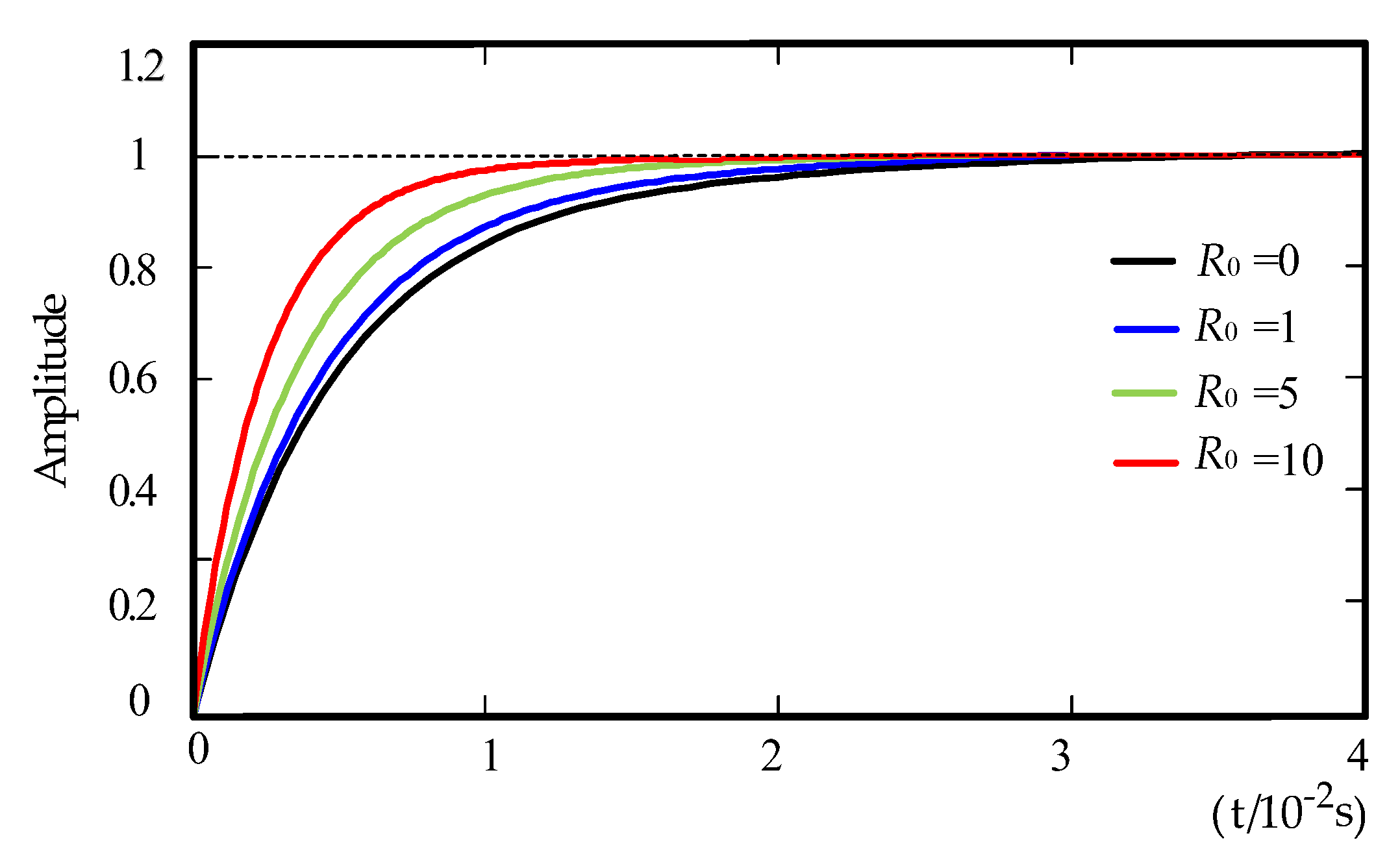
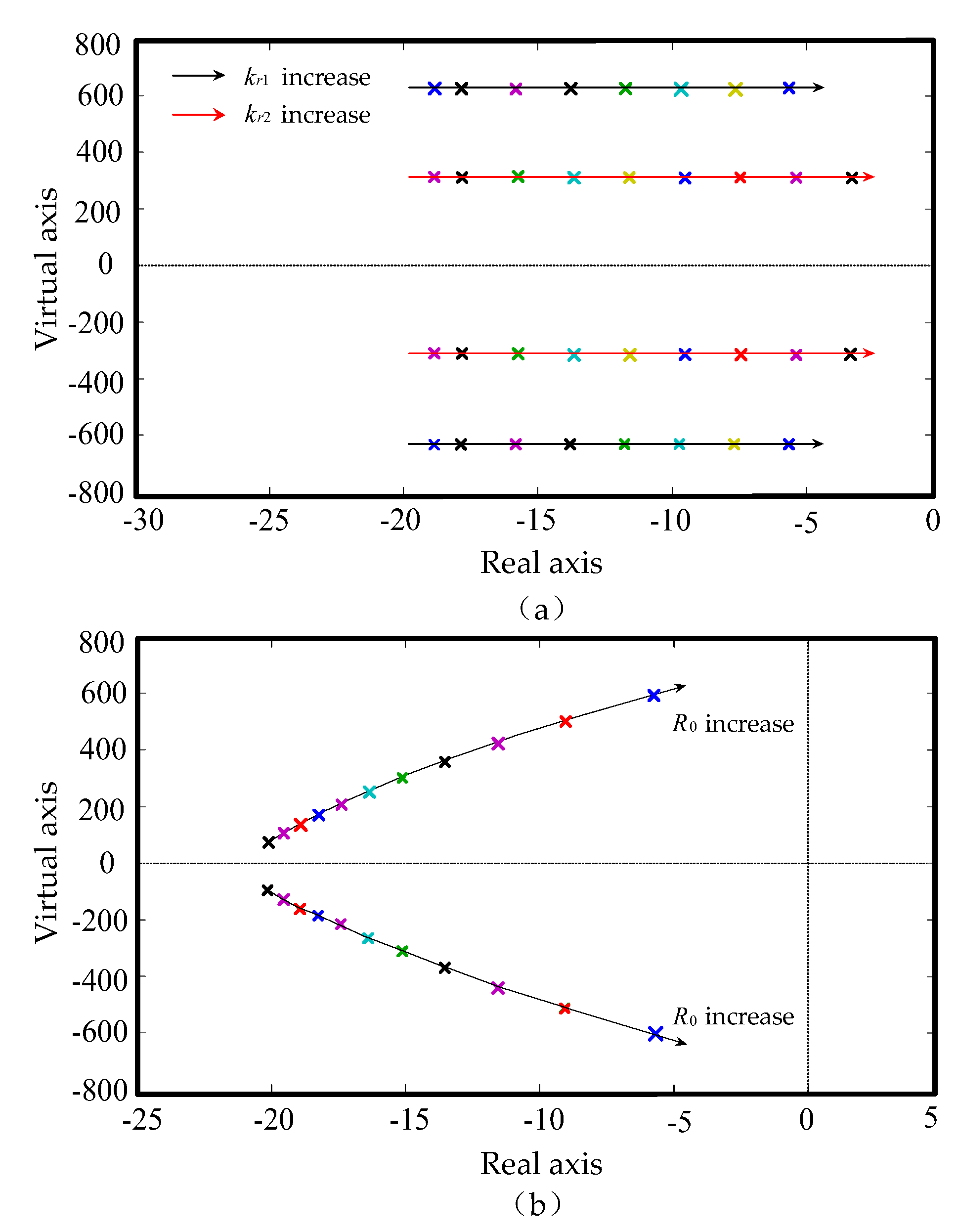
- The stability performance of the proposed controller is analyzed by using the Root-Locus criterion. It reveals that the response speed of the whole fault-tolerant controller can be accelerated by appropriately increasing the R0 value, and then appropriately reducing the resonant gain to ensure the stability of the control system.
- (4)
- The simulations in the MATLAB/SIMULINK environment and experiments with a 5-level prototype are all studied with the proposed controller under different fault conditions. The results confirm the efficiency of the control strategy.
Acknowledgments
Author Contributions
Conflicts of Interest
References
- Marquardt, R. Stromrichterschaltungen mit Verteilten Energiespeichern. German Patent DE10103031A1, 24 January 2001. [Google Scholar]
- Saeedifard, M.; Iravani, R. Dynamic performance of a modular multilevel back-to-back HVDC system. IEEE Trans. Power Deliv. 2010, 25, 2903–2912. [Google Scholar] [CrossRef]
- Bergna, G.; Berne, E.; Egrot, P. An energy-based controller for HVDC modular multilevel converter in decoupled double synchronous reference frame for voltage oscillation reduction. IEEE Trans. Ind. Electron. 2013, 60, 2360–2371. [Google Scholar] [CrossRef]
- Simon, P.T. Modeling the Trans Bay Cable project as voltage-sourced converter with modular multilevel converter design. In Proceedings of the IEEE Power and Energy Society General Meeting, Detroit, MI, USA, 24–29 July 2011; pp. 1–8. [Google Scholar]
- Abdelsalam, M.; Tennakoon, S.; Griffiths, A.L.; Marei, M. Investigation of sub-module fault types of modular multi-level converters in HVDC networks. In Proceedings of the International Universities Power Engineering Conference (UPEC), Stoke, UK, 1–4 September 2015; pp. 1–6. [Google Scholar]
- Jiang, W.; Wang, C.; Wang, M. Fault detection and remedy of multilevel inverter based on BP neural network. In Proceedings of the Asia-Pacific Power and Energy Engineering Conference (APPEEC), Shanghai, China, 27–29 March 2012; pp. 1–4. [Google Scholar]
- Moon, J.W.; Kim, C.S.; Park, J.W. Circulating current control in MMC under the unbalanced voltage. IEEE Trans. Power Deliv. 2013, 28, 1952–1959. [Google Scholar] [CrossRef]
- Son, G.; Lee, H.J.; Nam, T. Design and control of a modular multilevel HVDC converter with redundant power modules for noninterruptible energy transfer. IEEE Trans. Power Deliv. 2012, 27, 1611–1619. [Google Scholar]
- Konstantinou, G.; Pou, J.; Ceballos, S. Active redundant sub-module configuration in modular multilevel converters. IEEE Trans. Power Deliv. 2013, 28, 2333–2341. [Google Scholar] [CrossRef]
- Liu, G.; Xu, Z.; Xue, Y. Optimized control strategy based on dynamic redundancy for the modular multilevel converter. IEEE Trans. Power Electron. 2015, 30, 339–348. [Google Scholar] [CrossRef]
- Li, S.; Wang, Z.; Wang, G. Fluctuation volt age control and fault-tolerant operation of modular multilevel converters with zero-sequence injection. Int. Trans. Electr. Energy Syst. 2014, 24, 944–959. [Google Scholar] [CrossRef]
- Shen, K.; Xiao, B.; Mei, J. A modulation reconfiguration based fault-tolerant control scheme for modular multilevel converters. In Proceedings of the IEEE Applied Power Electronics Conference and Exposition (APEC), Long Beach, CA, USA, 17–31 March 2013; pp. 3251–3255. [Google Scholar]
- Yang, Q.; Qin, J. A post-fault strategy to control the modular multilevel converter under submodule failure. IEEE Trans. Power Deliv. 2012, 27, 1538–1547. [Google Scholar]
- Hu, P.; Jiang, D.; Zhou, Y. Energy-balancing control strategy for modular multilevel converters under submodule Fault Conditions. IEEE Trans. Power Electron. 2014, 29, 5021–5029. [Google Scholar] [CrossRef]
- Deng, F.; Tian, Y.; Zhu, R. Fault-tolerant approach for modular multilevel converters under submodule faults. IEEE Trans. Power Electron. 2016, 63, 7253–7263. [Google Scholar] [CrossRef]
- Lu, Z.; Chen, Z.; Gong, Y. Sub-module fault analysis and fault-tolerant control strategy for modular multilevel converter. In Proceedings of the International Conference on AC and DC Power Transmission (ACDC 2016), Beijing, China, 28–29 March 2016; pp. 1–5. [Google Scholar]
- Zhou, Y.; Jiang, D.; Guo, J. Control of modular multilevel converter based on stationary frame under unbalanced AC system. In Proceedings of the International Conference on Digital Manufacturing and Automation (ICDMA), Guilin, China, 31 July–2 August 2012; pp. 293–296. [Google Scholar]
- Wang, Z.; Zhang, A.; Zhang, H. Control strategy for modular multilevel converters in sub-module fault state. In Proceedings of the IEEE Conference on Industrial Electronics and Applications (ICIEA), Auckland, New Zealand, 15–17 June 2015; pp. 369–374. [Google Scholar]
- Wang, Z.; Zhang, A.; Zhang, H. Control strategy for modular multilevel converters with redundant sub-modules using energy reallocation. IEEE Trans. Power Electron. 2015, 30, 339–348. [Google Scholar] [CrossRef]
- She, X.; Huang, A.; Ni, X. AC circulating currents suppression in modular multilevel converter. In Proceedings of the IEEE Industrial Electronics Society, Annual Conference (IECON), Montreal, QC, Canada, 25–28 October 2012; pp. 191–196. [Google Scholar]
- Li, S.; Wang, X.; Li, T. Circulating current suppressing strategy for MMC-HVDC based on nonideal proportional resonant controllers under unbalanced grid conditions. IEEE Trans. Power Electron. 2015, 30, 387–397. [Google Scholar] [CrossRef]
- Guan, M.; Xu, Z. Control and modulation strategies for modular multilevel converter based HVDC system. In Proceedings of the IEEE Industrial Electronics Society, Annual Conference (IECON), Melbourne, Australia, 7–10 November 2011; pp. 849–854. [Google Scholar]


| Parameters | Value |
|---|---|
| Ac system nominal voltage | 10 kV |
| Ac System inductance Ls | 5 mH |
| Fundamental frequency | 50 Hz |
| Ac system power losses Rs | 0.03 Ω |
| Arm inductance Lm | 5 mH |
| Series arm resistance Rm | 0.01 Ω |
| Dc bus voltage Udc | 20 kV |
| Number of SMs per arm N | 20 |
| Number of redundant SMs per arm nm | 5 |
| Sub-module capacitor C | 2000 μF |
| Transformer ratio | 1:1 (Y/Δ) |
| Parameters | Value |
|---|---|
| Dc bus voltage Udc | 240 V |
| Ac System inductance Ls | 5 mH |
| Fundamental frequency | 50 Hz |
| Arm inductance Lm | 5 mH |
| Number of SMs per arm N | 4 |
| Number of redundant SMs per arm nm | 1 |
| Sub-module capacitor C | 2000 μF |
| Transformer ratio | 1:1 (Y/Δ) |
| The value of virtual resistance R0 | R0 = 0 | R0 = 5 | R0 = 10 |
| Twice peak value of the circulating current at t3 moment 2icirm | 11.40 A | 7.88 A | 6.17 A |
| Excessive ratio of the circulating current η | 1.59 | 0.79 | 0.40 |
© 2017 by the authors. Licensee MDPI, Basel, Switzerland. This article is an open access article distributed under the terms and conditions of the Creative Commons Attribution (CC BY) license (http://creativecommons.org/licenses/by/4.0/).
Share and Cite
Wu, W.; Wu, X.; Yin, J.; Jing, L.; Wang, S.; Li, J. Characteristic Analysis and Fault-Tolerant Control of Circulating Current for Modular Multilevel Converters under Sub-Module Faults. Energies 2017, 10, 1827. https://doi.org/10.3390/en10111827
Wu W, Wu X, Yin J, Jing L, Wang S, Li J. Characteristic Analysis and Fault-Tolerant Control of Circulating Current for Modular Multilevel Converters under Sub-Module Faults. Energies. 2017; 10(11):1827. https://doi.org/10.3390/en10111827
Chicago/Turabian StyleWu, Wen, Xuezhi Wu, Jingyuan Yin, Long Jing, Shuai Wang, and Jinke Li. 2017. "Characteristic Analysis and Fault-Tolerant Control of Circulating Current for Modular Multilevel Converters under Sub-Module Faults" Energies 10, no. 11: 1827. https://doi.org/10.3390/en10111827
APA StyleWu, W., Wu, X., Yin, J., Jing, L., Wang, S., & Li, J. (2017). Characteristic Analysis and Fault-Tolerant Control of Circulating Current for Modular Multilevel Converters under Sub-Module Faults. Energies, 10(11), 1827. https://doi.org/10.3390/en10111827