1. Introduction
Through development for more than 40 years, the characteristic performances of brushless PM motors are approaching their limits [
1,
2,
3,
4,
5,
6], and there are strong needs for new motors with higher power densities. Under these circumstances, the PM vernier machine is being actively studied as an alternative [
7,
8,
9,
10,
11,
12]. This PM motor uniquely utilizes an extra flux so-called modulation flux due to the magnetic modulation effects as well as the regular PM flux. Owing to these effects, the vernier motors produce much higher back EMF and higher power density than general PM motors.
As is already known that in order to establish the modulation effects, the special combinations of slots/magnets should be met. In this case, the vernier machine generally requires significantly more PM poles than a conventional PM machine, if they have the same number of winding poles. Such a vernier machine having many PM poles operates with much higher frequency than conventional machines, which leads to significant reactance and then causes the poor power factor and concerns about excessive increase in iron loss. Thus, vernier machines are considered suitable for low speed and high torque applications. However, this assessment seems unfair because the problems are valid when the vernier motor is compared to a conventional PM machine with the same number of winding poles, not a machine with the same number of PM poles. Thus, the reliable evaluation of competitiveness of the PM vernier machine is necessary, but there are as of yet few studies on the comparison of vernier and conventional PM motors with fair conditions.
On the other hand, to compare a vernier and a conventional PM machine fairly, both machines should be designed with same flux density level in air gap as well as iron cores. In this respect, the presence of the modulation flux of a vernier machine provides additional considerations in the iron core design as follows. In general, the number of PM poles is closely related with the yoke structure of PM machines, that is, the thicknesses of yoke and teeth of a PM machine are inversely proportional to the number of PM-poles [
13,
14]. However, this is not exactly true for a vernier PM machine because of its additional modulation flux apart from the regular PM flux. Thus, it is required to take into account the modulation flux effects on the iron core design, but there are only a few studies on the analysis of the core losses of a vernier motor [
11], not on the design of the machine considering the modulation flux and core losses.
Therefore, in this study, the modulation flux effects on the core design of a PM vernier machine are investigated and the competitiveness of the vernier over conventional PM machines are evaluated in fair conditions. To these ends, first, the air gap flux distribution is presented in the form of analytical expressions in consideration of all working fluxes in the vernier motor which consist of the modulation flux, the regular PM flux, and the flux from stator windings. Using the equations of air gap flux, the yoke and teeth fluxes of a PM vernier machine operating at the base speed are formulated. For verification of these ideas, 12-slots, 20-PM poles, and full-pitch winding, a PM vernier motor is designed in which the yoke thickness is determined to get a general yoke flux density, 1.2 T by using the obtained formula. Next, to compare the features of a PM vernier machine in aspects of the machine’s volume and the performance characteristics, two conventional PM motors are additionally designed with the same procedures. One has the same stator winding pole-pairs as the vernier motor, and the other has the same rotor PM pole-pairs as the vernier motor. The time-step FE simulations are carried out for the three designed motors at no-load and load conditions. Especially, from the FE-simulation results of the air gap flux densities of vernier motor, the modulation and the general PM fluxes are extracted, and their unique characteristics and effects on yoke flux are explained. In addition, the core losses are also calculated considering hysteresis and eddy current losses of core. As a result, the volume issues as well as the performance characteristics—such as back EMF, torque, and efficiency—of each model are compared, and finally the competitiveness of the vernier machine is evaluated.
2. Design Consideration of Core Parts of a PM Vernier Machine
2.1. Flux Densities of Teeth and Back Yoke
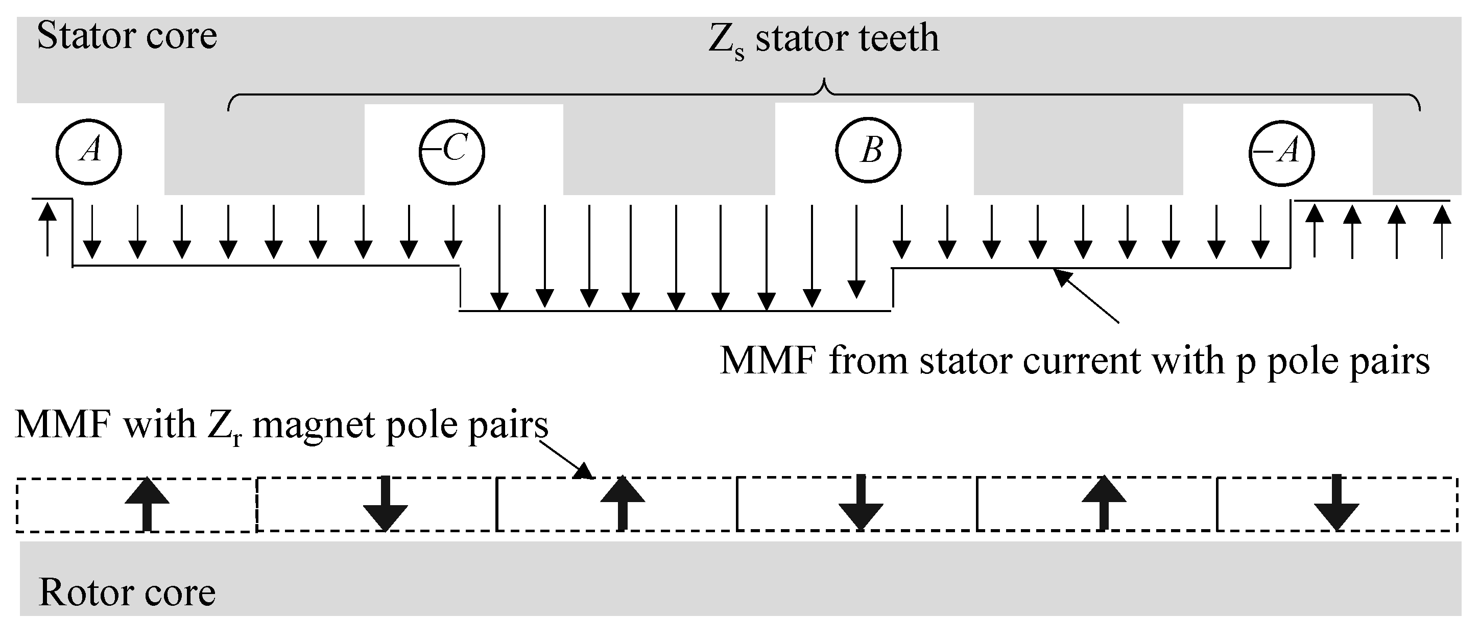
Figure 1 shows the structure of a PM machine in which p is the number of winding pole pairs, Z
s and Z
r are the number of stator slots and rotor PM pole pairs, respectively. In order to get the vernier effects, the special condition, Z
r − Z
s = −p should be satisfied, while normally Z
r = p for a traditional PM machine. Since Z
s = 6pq where q is slots/phase/pole, the condition is alternatively given as Z
r = p (6q − 1).
The magneto-motive force (MMF) of air gap, F
g is given by (1) which consists of F
w and F
pm due to stator currents and rotor PMs. In (1), θ
m is rotor angular position, F
m1 is given as 4/π∙B
r/μ
m∙gm where B
r and μ
m are the magnetization and permeability of PM, and g
m is PM thickness. In addition, F
w1 is 3/π∙k
w1N
ph∙I
ph.max/p, where k
w1 is the winding factor, N
ph is the total series number of turns of a phase, and I
ph.max is the maximum phase current. In particular, the (−) sign in (1) is for a conventional machine and the (+) is for a vernier machine and it will be explained in
Section 3.
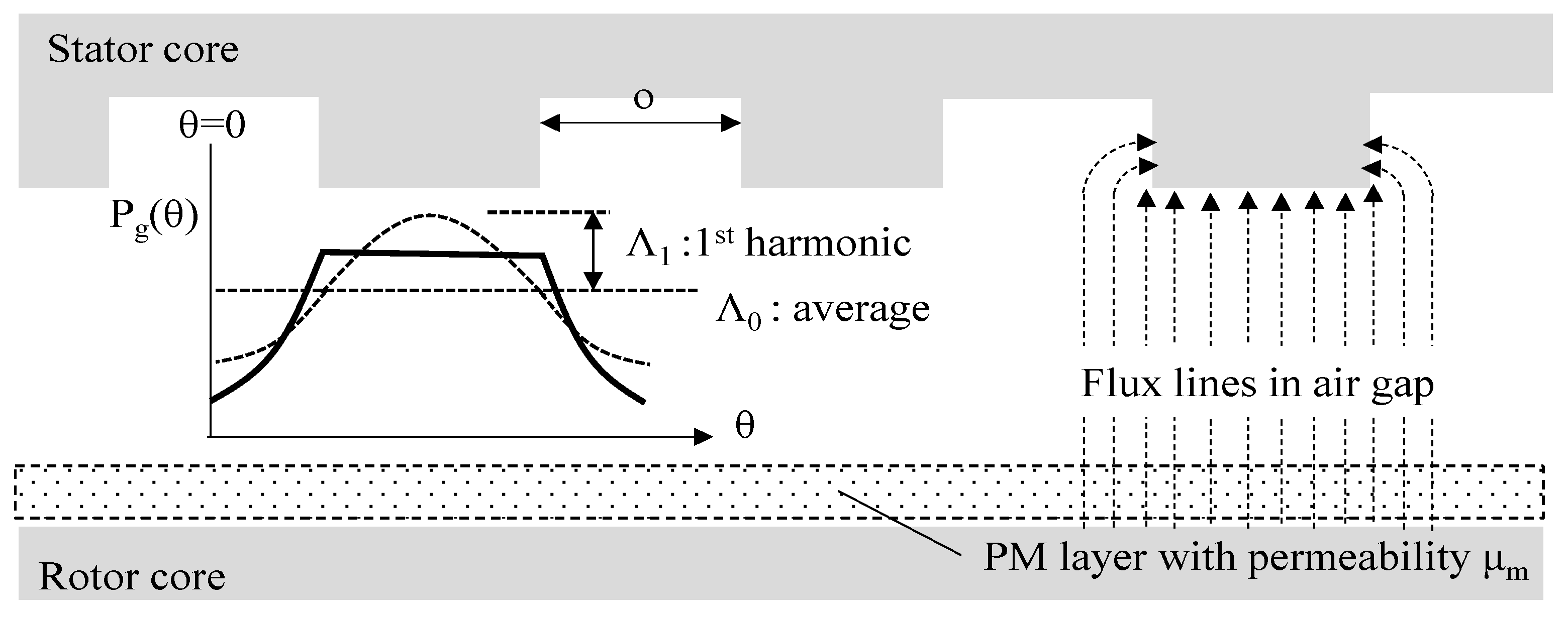
The specific permeance function of air gap, P
g developed by the classical conformal mapping method as shown in
Figure 2 is expressed with the terms of the average and the first harmonic of air gap permeance [
15], and is given in (2) when the ratio c
0 between slot pitch to slot open o is 0.5 by following the previous study [
7,
9], where is the (−) sign in front of Λ
g1 is due to the reference position of θ at the center of slot, and the factor β in (2) is given as (3). In addition, g
m+a is the effective air gap length.
Under the vector control strategy, the air gap flux of a PM machine is kept maximal up to the base speed in which the both MMFs of F
pm and F
w are orthogonal to each other [
16]. Thus, the maximal air gap flux is obtained by multiplying F
g of (1) and P
g of (2) with φ = π/2, and given as (4) by ignoring the harmonic with the term of Z
r + Z
s because its speed is very low, consequently developing negligible back EMF.
The air gap flux density of a traditional PM machine is obtained by replacing Z
r in (4) with p, as (5a). It shows that B
g1 and B
g3 have the same pole p, and thus, their interaction produces active torque. It should be noted that B
g2 and B
g4 have also the same pole p (6q − 1), but their magnitudes are both small and their interaction—that is, the multiplication—becomes much smaller. Furthermore, F
m1 is even greater than F
a1, and Λ
g0 is also greater than Λ
g1, and thus the air gap flux density of a conventional PM machine, B
g.con is finally approximated as (5b).
Applying the condition that Z
r − Z
s = −p to (4), the flux density of a vernier machine is obtained as (6a) which describes that B
g1 interacts with B
g2, and B
g3 interacts with B
g4 as well. That is why the vernier PM motor obtains higher torque than the conventional PM motor. The flux density is approximated as (6b) where the angle ϕ
ver is given by tan
−1 (F
w1Λ
0/0.5F
m1Λ
1).
By integrating B
g.ver of (6b) over 1 pole area of stator winding and a tooth area, the amount of flux in the back yoke and the tooth of a vernier motor are obtained as (7) and (8), respectively, where Z
r = p (6q − 1) is used in the calculation. Reminding Z
r is quite bigger than p, B
ver/p due to vernier effects in (7) and (8) can be considerable, demonstrating why they should be taken into account in design of yoke and tooth.
2.2. Core Design Considering Modulation Flux
To check the validity of the proposed ideas, a PM vernier motor with p = 2, q = 1 and Z
r = 10 is assumed whose PM is made from NdFeB. With the given air gap diameter and magnet thickness, the values of Λ
g0 and Λ
g1 are calculated by using (2) and (3), and then the flux of core parts can be estimated by using (7) and (8). Using the estimated values, the yoke thickness is determined to employ the general yoke flux density, 1.2 T, considering the stator current as well. On the other hand, the tooth width is chosen to the same of the slot open width not to interrupt vernier effects since it is bigger than the width calculated from (8). The general specifications of the designed machine and the calculated information are listed in
Table 1 where K
s is the surface current density and J is the volume current density. It is seen that
/p is nearly the same as
/Z
r, showing that the effect of the modulation flux is considerable as expected.
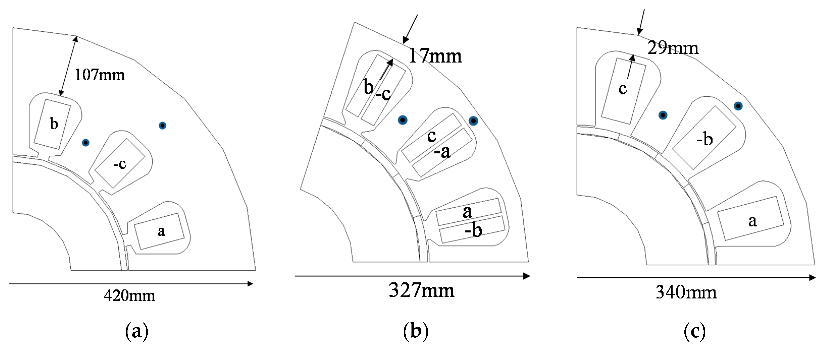
To compare performance characteristics of the designed vernier PM motor, two conventional PM motors are additionally designed. The one is a full-pitch winding (FW) PM motor with the same 12 slots as the vernier machine, while it has 4 PM poles since Z
r = p = 2. The other one is a fractional slot-concentrated winding (CW) PM motor with the same 20 PM poles on rotor as the vernier motor, while it has 15 stator slots by employing the popular slots/PM poles ratio of 3/4. For fair comparison, both machines are designed with same conditions, which means the magnet thickness, air gap radius, total number of conductors, and stack length are all same as those of the vernier machine in
Table 1, thus the magnetic loading of the machines is identical to each other. In addition, the both machines are designed to keep the same surface current and volume current densities in
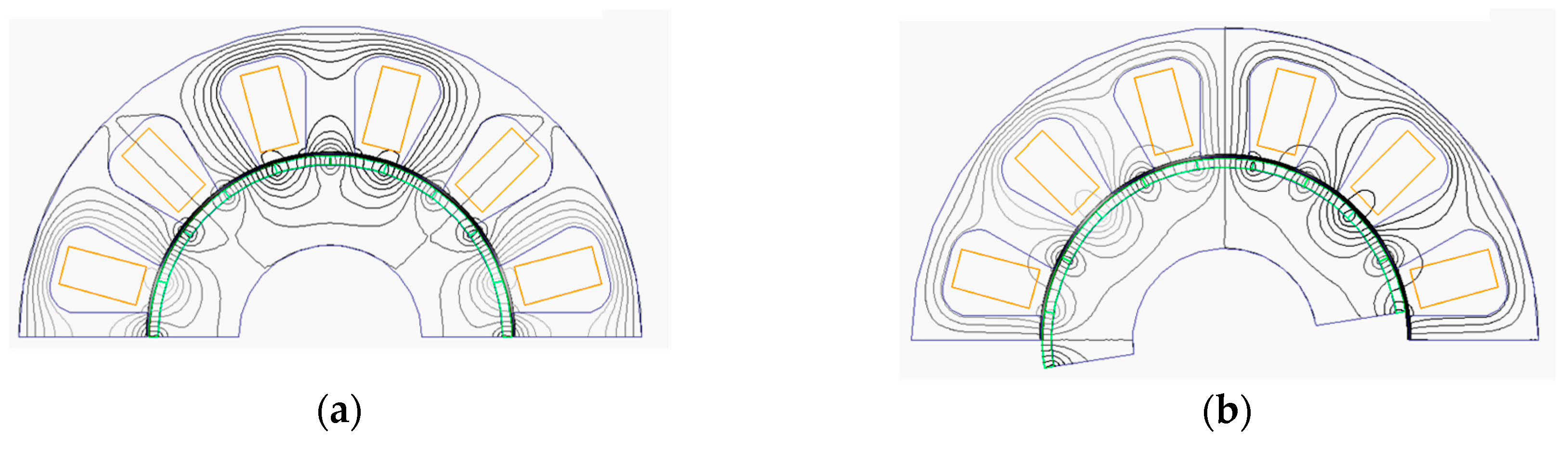
Table 1, so the electric loadings of the machines are also same and then the temperature rises are expected to similar. The designed machines are depicted in
Figure 3 where every machine has the identical air gap radius. It is seen that the yoke thickness of the conventional FW-PM motor is much greater than those of other two machines, to be exact, 1.65 times of volume of the conventional CW PM motor. It is mainly due to its small number of PM poles. On the other hand, even though the number of PMs of the both conventional CW and the vernier PM motor are same, the yoke thickness of the vernier PM motor is almost twice of that of the CW-PM motor, which is clearly due to the modulation flux. However, the overall volumes of the both motors are quite similar. To be exact, the vernier motor has 1.08 times the volume of a conventional CW-PM motor.
3. FE-Simulation Results
3.1. Analysis of Modulation Flux in Air Gap
To verify the modulation flux effects of the vernier motor, no-load flux distributions are first analyzed with FEM with different rotor position.
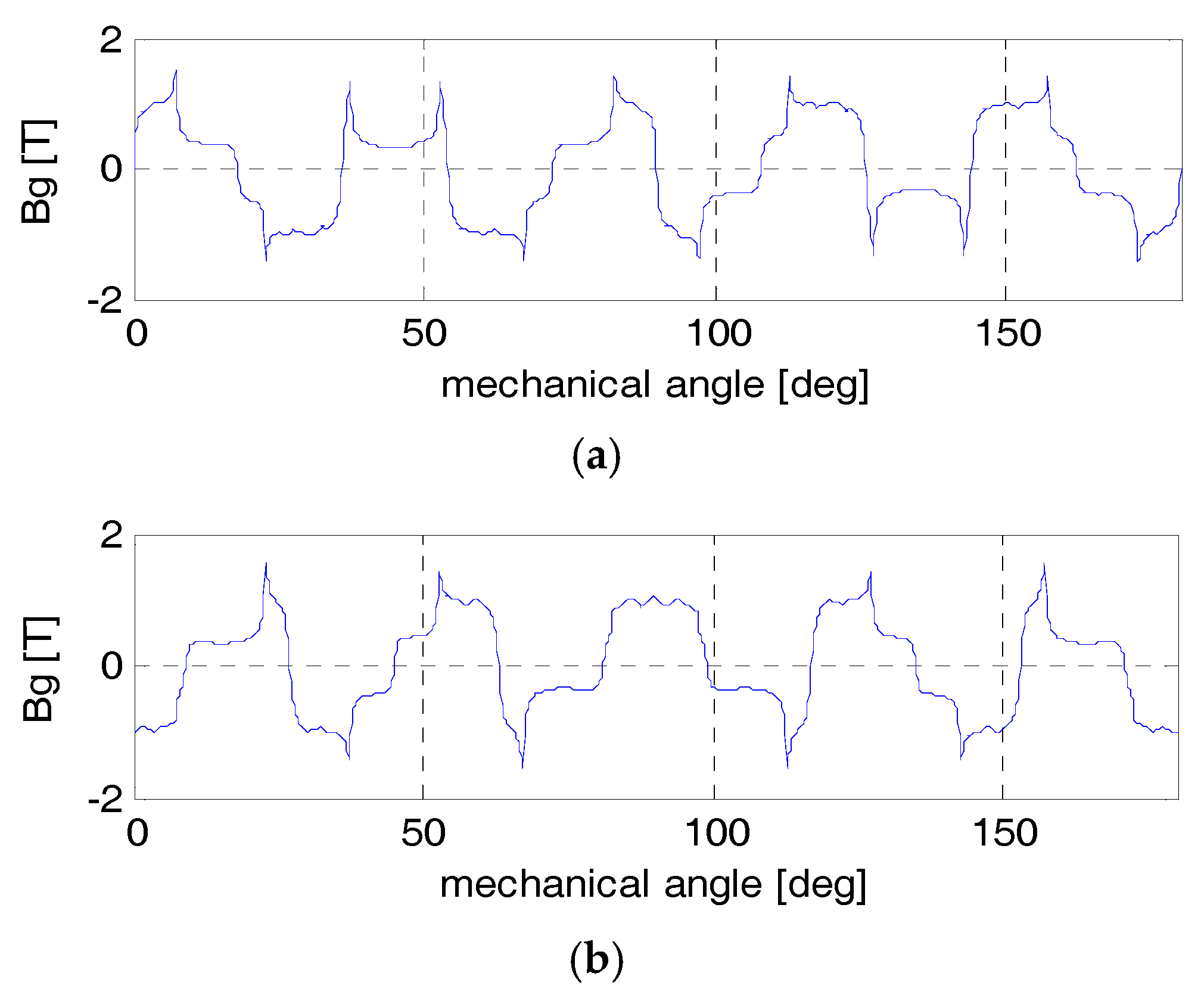
Figure 4 and
Figure 5 show the flux lines and air gap flux density of the vernier motor when the rotor is located at the different positions of θ
m = 0° and 9°, respectively.
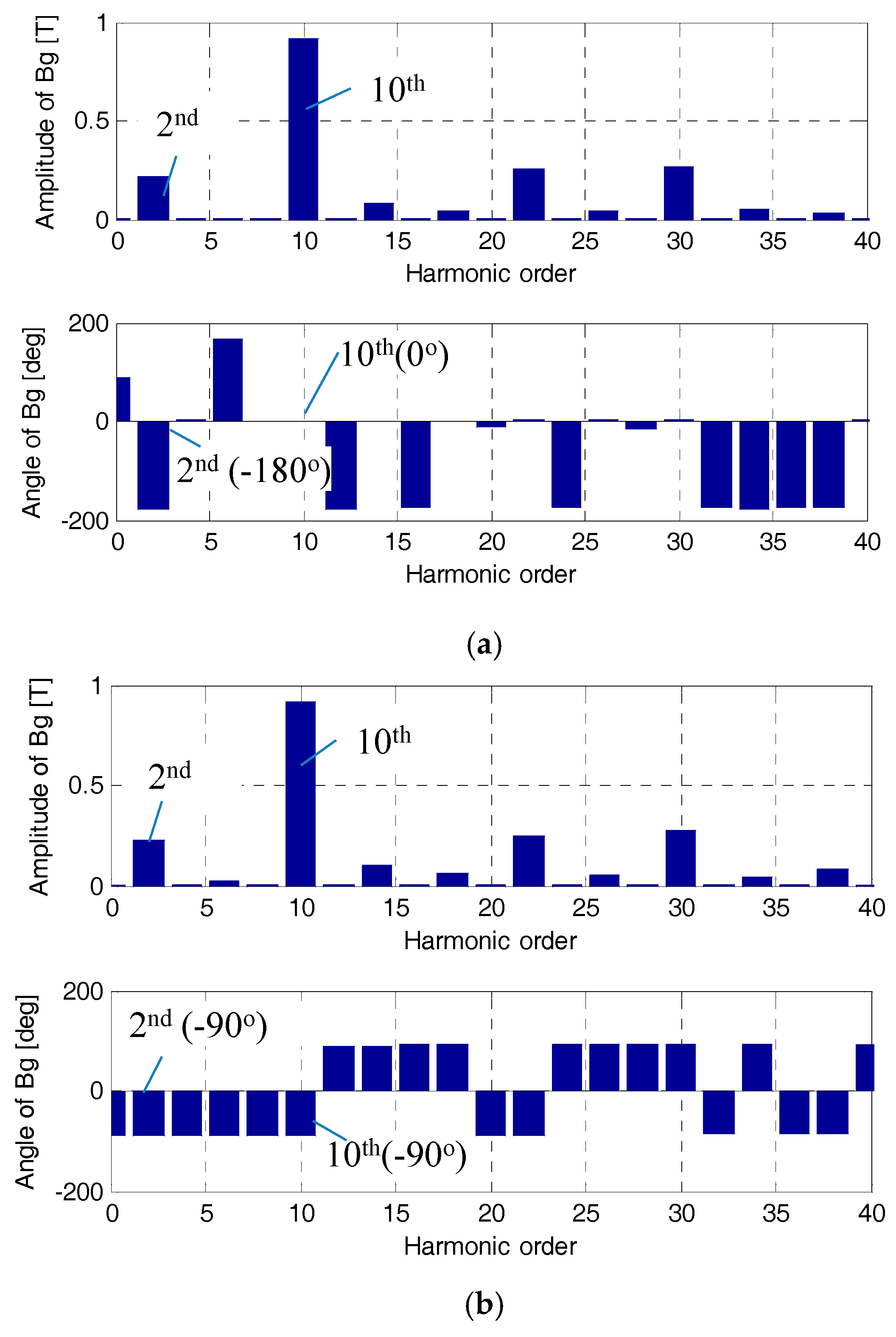
The two air gap flux waveforms in
Figure 5 are decomposed into various harmonics through Fourier series expansion. The phase angles as well as the magnitudes of the harmonics are depicted in
Figure 6. It is shown that the magnitudes are almost same regardless the rotor positions but their angles vary, meaning the harmonics are moving. In particular, the 2nd harmonic has the same pole pair of the winding p, and the 10th harmonics has the same pole pair of the magnet Z
r, consequently representing the modulation and the regular PM flux, respectively. To check the speed of the harmonic waves, using the phase angles in
Figure 5, the mechanical angular distance of kth harmonic wave while the rotor moves from θ
m = 0° to 9° can be obtained by
where θ
e.n is the phase angle of the nth harmonic. From (9), it is apparent that the higher n is, the slower the wave speed is, that is why the 22nd and the 30th can be neglected because of their slow speeds, and consequent small contribution to the back EMF.
The angular distances of the 2nd and the 10th harmonics are calculated by using (9), as −900°/2 and 900°/10, describing that the 10th wave, the general PM flux moves with the same speed and in the same direction as the rotor, but the 2nd wave, the modulation flux does with five times speed and in the opposite direction of the rotor, which is the reason for choosing the (+) sign in (1).
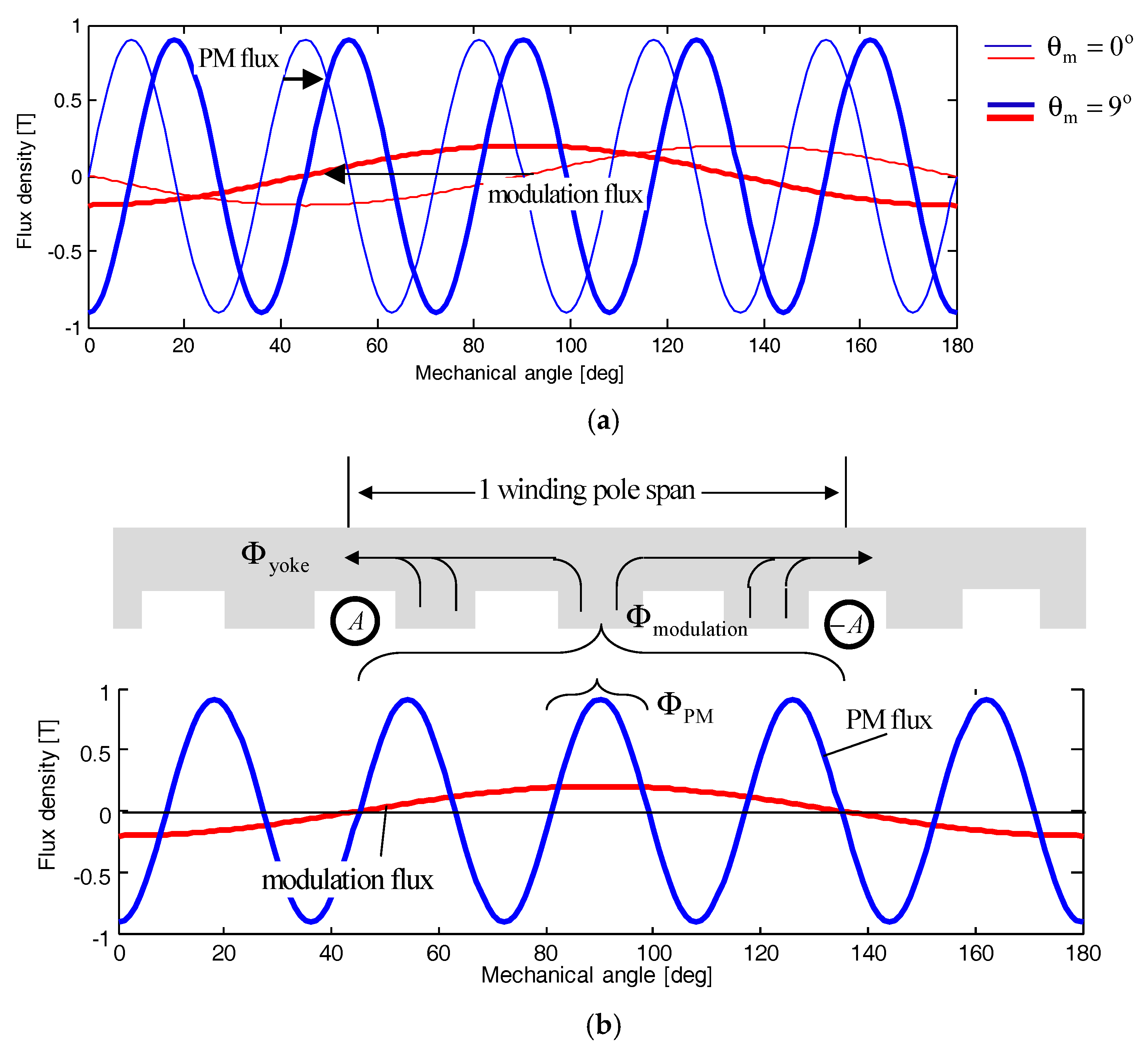
For a better understanding of the operation principle, both waves are plotted in
Figure 7a for each instance θ
m = 0° and 9° by using the results of
Figure 6. It clearly shows the modulation effects of the PM vernier motor. It should be noted that the voltages induced by the both waves are additive in spite of their opposite directions.
In addition, in order to show the relation of the air gap flux and core flux, both waves at θ
m = 9° are depicted again in
Figure 7b. This demonstrates that all of the modulation flux in a winding pole area contribute to core flux even though its magnitude is quite small, but the fluxes of four poles of the general PM flux wave cancel each other and only one pole flux passes through the winding pole area, which effectively explains why the modulation flux should be considered in the core design.
3.2. Analysis of Core Flux Densities and Losses
To estimate the core flux densities and losses of the motors, the time step FE analyses are carried out at 500 rpm at the load conditions with a phase current of 80 A(rms) to meet K
s = 20 A/mm in
Table 1.
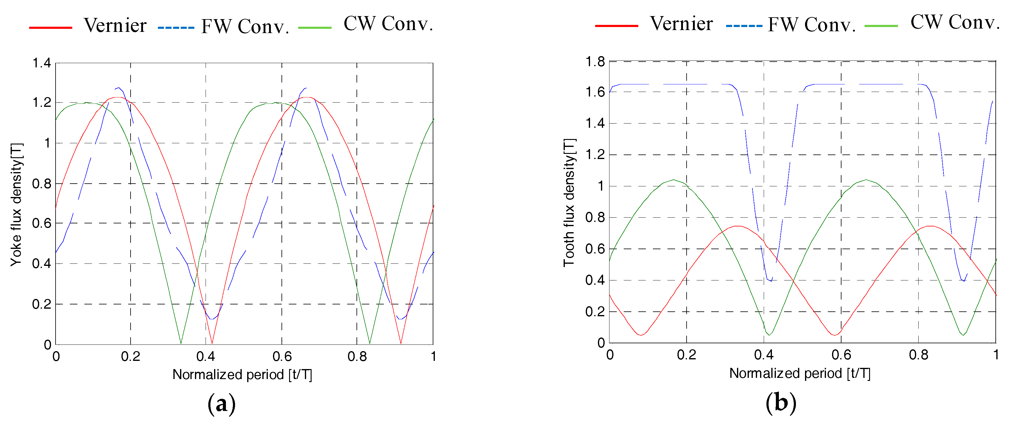
Figure 8 shows the yoke and tooth flux densities at the centers of tooth and back yoke designated in
Figure 3. The maximum yoke density of each motor is very close to the desired value 1.2 T, indicating that the derived equations and proposed design procedures are very valid. In the case of the teeth, the conventional FW-PM motor has much higher flux density than others. In particular, the vernier motor has the flux density less than 0.8 T, meaning there is no need to concern about the saturation in the teeth as expected in
Section 2.
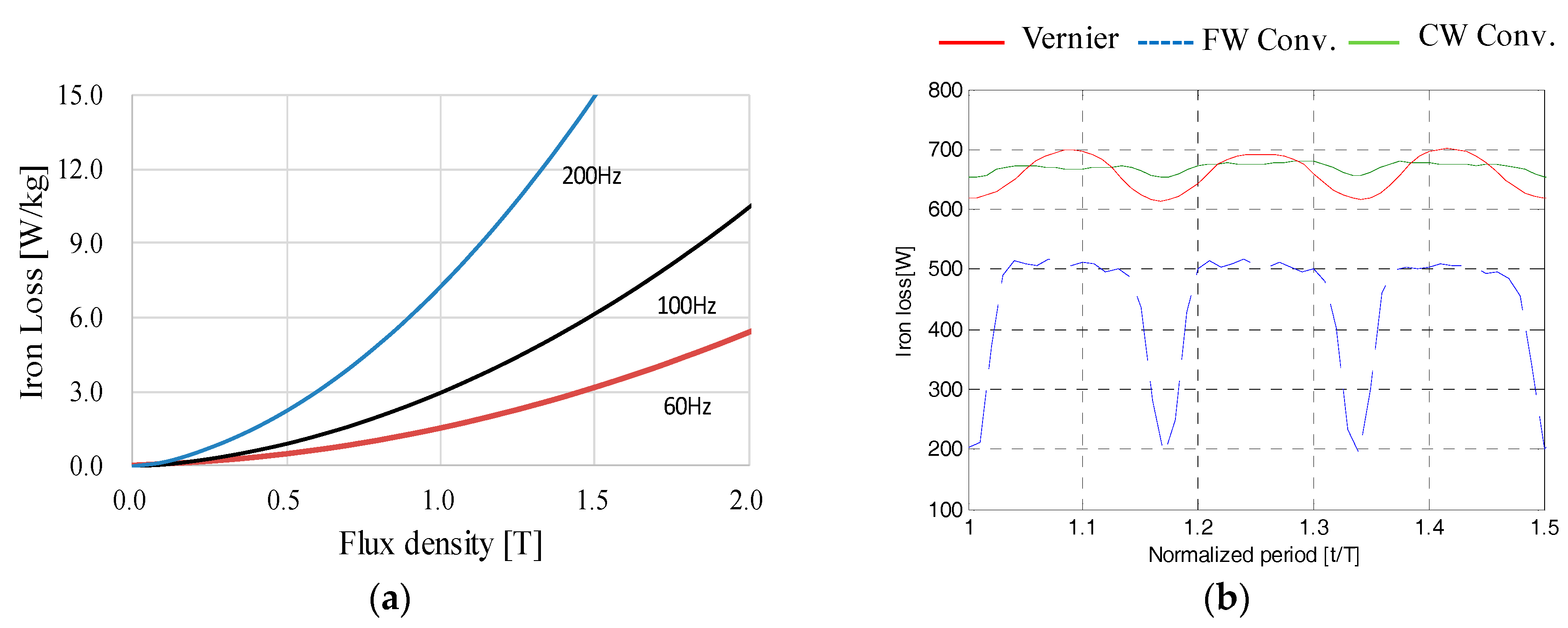
Since the electrical frequency of the conventional FW-PM motor with 4 PM poles is substantially different from those of the other two motors with 20 PM poles, their iron losses should be checked carefully. To this end, the following classical core loss Equation (10) is used.
where k
h, k
c, and k
e are the coefficients of hysteresis, classical eddy current, and excess eddy current losses, respectively. The coefficients are estimated by using the loss characteristics of Si-steel in
Figure 9a provided by manufacturer. The iron losses of the motors are calculated by (10) during FE-simulation.
Figure 9b shows that the transient iron losses, and their average values are 400 W for the conventional FW-PM motor and almost same 650 W for other two motors.
3.3. Characteristics of Back EMF, Torque, and Efficiency
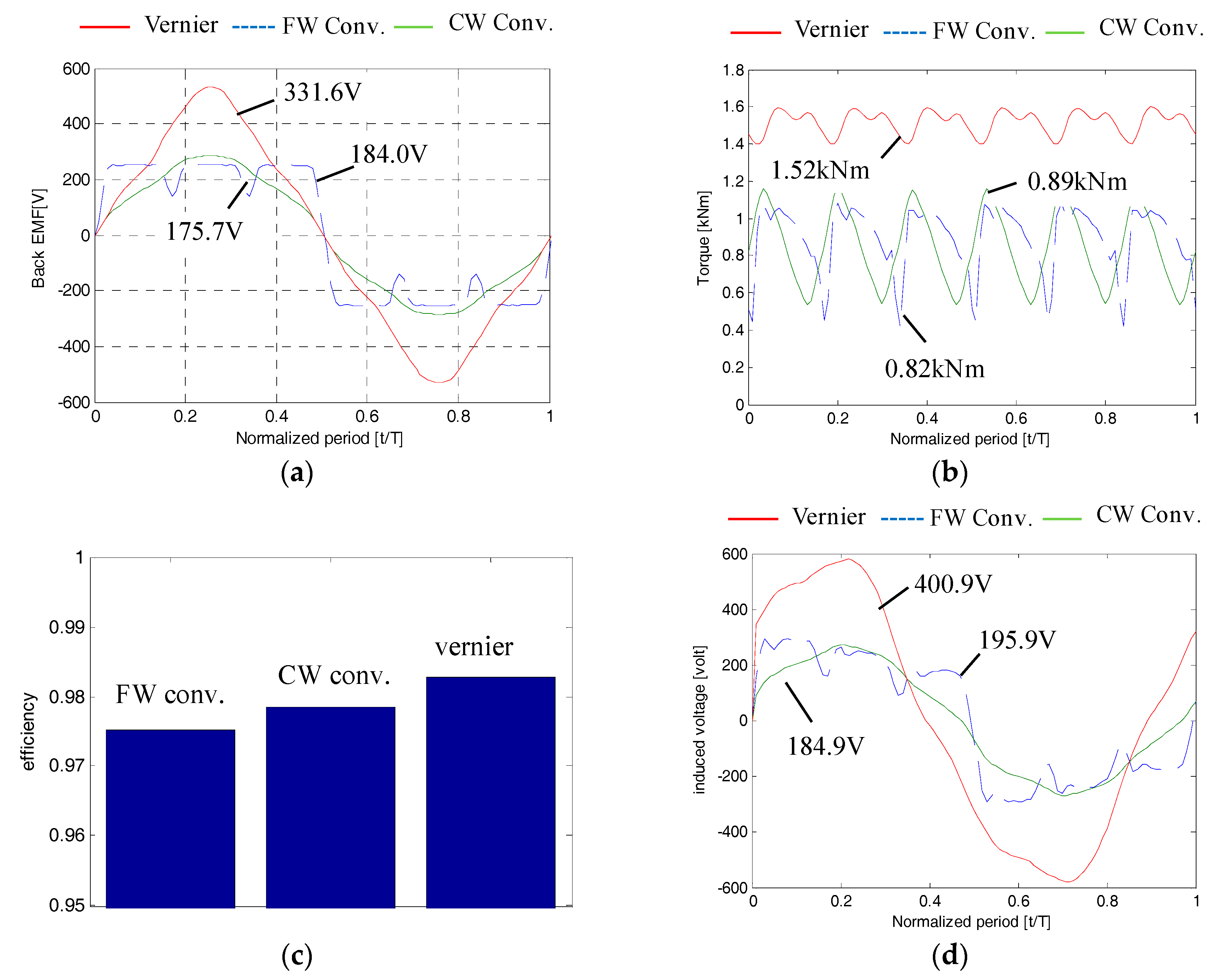
The FE simulation results of the no-load back EMF and the torque with the load current 80 A are shown in
Figure 10a,b. It is apparent that the vernier motor produces much higher back EMF and thus higher torque with same current. To be exact, 1.8 times back EMF and torque of the CW-PM motor are produced. Recalling the volumes of the vernier and the SC-PM motor are similar, this result evidently proves higher power characteristics density of the vernier PM motor owing to the modulation flux. Furthermore, in case of vernier motor, the difference between the numbers of slots and PM poles is bigger than other conventional motors, and thus the torque ripple characteristic of the vernier motor is also superior to the conventional ones.
To investigate the efficiencies of the motors, the copper losses are additionally calculated. With the slot fill of 45%, the winding resistances of the conventional FW and the vernier PM motor are estimated as same 38.1 mΩ, while that of the SC convention motor is 16.6 mΩ, and thus resulting in 730.2 W and 319.8 W for the copper losses, respectively. Using the copper and core losses and the output power, the efficiencies are calculated and compared in
Figure 10c. Since there is no consideration of the extra losses such as eddy current losses in magnets and friction losses, the practical efficiencies could be lower, however, it is certain that the vernier motor has similar or slightly higher efficiency compared with others.
Lastly, the total induced voltage in a phase winding with the load current and their waveforms and root-mean square values are depicted in
Figure 10d. Since the voltage are the sum of back EMF and the voltage due to synchronous reactance, it can be considered as the necessary phase voltages to inject the load current, neglecting stator resistance, which is consequently related to the power factors of the motors. It can be seen that the vernier motor needs about 2.2 times input voltage of the conventional PM motors. Since the back EMF is in phase with winding current, the power factor can be expressed by
The power factors for both conventional PM machines calculated by (11) are about 94%, while that of the vernier motor is 83%, demonstrating that the vernier motor needs more reactive power than a conventional motor. However, it is considered that the power factor is not so bad and the disadvantage of the low power factor characteristic can be overcome by the highly increased output power characteristics.
4. Conclusions
In this study, the analytical expression for flux in the back yoke as well as teeth considering the modulation flux of a vernier PM motor are proposed. From the proposed expressions, it was found that the modulation flux has considerable effects on the flux density in core, especially in the back yoke. A prototype vernier PM motor with full pitch windings is designed to get 1.2 T of yoke flux density by using the proposed equations. To evaluate the applicability of the designed vernier motor, it is compared with two conventional PM motors designed to get the same flux density level. Herein, one of the two motors is the full pitch (FW) motor with the same number of the slots of the vernier motor and the other is the slot-concentrated windings (CW) motor with the same number of the magnets of the vernier motor, respectively.
The results can be summarized as follows. First of all, regarding the overall volume of the motors, the conventional FW-PM motor has much thicker yoke, resulting in an excessively large motor volume which is 1.5 times of that of the vernier motor. On the other hand, the yoke thickness of the vernier motor is about double of that of the conventional CW-PM motor due to the modulation flux effects, but their overall volumes are similar, to be exact, the vernier motor has 1.01 times overall volume of the CW-PM motor. Thus, it can be said that the modulation flux effects should be considered in design of the yoke geometries of a vernier motor to avoid severe saturation of the yoke, but the effects on overall volume are quite small.
From the time step FE simulations carried out to get back EMF, torque and core losses and etc. for each designed motor, the features of the performance characteristics are concluded as follows. The vernier motor has higher, almost double, core loss than the FW-PM motor with less number of magnet poles, but having similar loss to the CW-PM motor with the same number of magnet poles. Thus, it seems that the concern about heavy core losses of the vernier motor is over estimated. The practical disadvantage is that the vernier motor has a lower power factor than the conventional motors. According to the simulation results, the power factor of the vernier motor is about 10% less than the conventional PM machines, which is not very bad. Rather, the vernier motor has 1.8 times output power of the both conventional PM motors, and consequently, the vernier motor has better efficiency characteristics compared to the conventional motors, which clearly demonstrates the advantage of the vernier motor. Finally, the applicability and competitiveness of vernier motors can be considered to be high.


