Article

Using an Integrated Script Control Unit (ISCU) to Assist the Power Electronics Education

School of Automation, Beijing Institute of Technology, Beijing 100081, China
*
Author to whom correspondence should be addressed.
Energies 2017, 10(11), 1802; https://doi.org/10.3390/en10111802
Submission received: 11 October 2017 / Revised: 29 October 2017 / Accepted: 1 November 2017 / Published: 8 November 2017

Abstract

:
An integrated script control unit (ISCU) is invented to work as the digital controller in power electronics educations. The ISCU mainly consists of two parts, a control board and computer software. The computer software enables college students to write specific scripts, which can be compiled and saved on the control board, to design the control flow and algorithms. The processor on the board will realize the algorithms that are designed by the user. All of the variables can be monitored by the computer software, which is helpful to find the bugs in the algorithms. ISCU can help the under-graduate students to design converters even if they are unfamiliar with the programming languages and developing environment. Users can write and validate algorithms for converters quickly without writing any tedious codes (such as initialization, dealing with the interrupts) for specific processors with ISCU. The college students who lack the necessary skills to program the processor, can benefit when they are studying the power electronic techniques. Importantly, the ISCU is considered to be free for everyone. The details and the principles of ISCU are introduced, and a bi-directional DC-DC converter is built based on ISCU to validate the proposed characteristics.

1. Introduction

In recent years, power electronic converters have gained much attention and are widely used in many industrial and commercial fields, such as motor drives, power sources, and wind power generation [1,2,3,4,5,6,7,8]. Digital processors are usually adopted because of their low cost, high reliability, and high performance. Some examples are described in [9,10,11,12]. Literature [9] studied the inherent relationship between two pulse width modulation methods for multilevel converters and carried out an experiment based on TMS320F2812. The processor sent the switching states to the ePWM module (digital-to-analog converter). The developer could set the ePWM module parameters and modify the registers according to the datasheet. In [10], the unbalanced-load correction capability of two H-bridge based on three-phase three-stage modular PET topologies are analyzed. The authors built a prototype and the control algorithm was programmed in Digital Signal Processing (DSP) chip TMS320F28335. Literature [11] presents a novel islanding search sequence technique that is applied to four islanding detection methods. A 32-bit CPU floating point DSP was used to implement the control firmware. In [12], a predictive torque control scheme for the B4 inverter-fed induction motor was proposed. The experimental setup was based on the 32-bit floating point DSP TI TMS320F28335.
The digital processors such as TMS320F2812 and TMS320F28335, are powerful enough to carry out the control algorithm in power electronic converters. Many proposals have been designed based on such chips. For example, literature [13] presents a full digital control design proposal by using TMS320F28335. Literature [14] also explains a current sensing technique for DC-DC converter by using TMS320F28335 DSP. In [15], general recommendations are given on utilizing TMS320F28335 digital signal controller as the controller for voltage source converters. What is more, literature [16] presents a hybrid control approach for the bi-directional DC-DC converter, and its prototype system is controlled by TMS320F2812 DSP. Besides, there are also some examples using similar chips, like TMS320F2808, for the overall control of various converters [17,18,19]. However, these chips are not easy to learn. There are lots of registers, modules, and peripherals on the chip. The user needs to write many codes to initialize the chip and control the peripherals. Usually in the authors’ lab, the post-graduate students need at least three months to learn and master the DSP TMS320F28335. Then, it is impossible for them to build a converter based on the chip, even when there are many documents and examples about the chip.
Typically, the under-graduate students in our university will study “Power Electronics” in grade three. They learn several kinds of converters such as buck converters, boost converters and rectifiers. However, because they are not familiar with the digital processors, they are not able to finish the experiments on their own. As a result, this prevents the students from getting a better understanding of the power electronics. They cannot try or design their own control algorithm for the converter because they are not able to handle the processor.
In order to help the college students to implement the control algorithm in power electronics converters quickly, integrated script control unit (ISCU) is proposed in this paper. It makes it possible to design the algorithm for a converter without writing any code for the processor. Figure 1 shows the concept of ISCU. The ISCU provides a script system, which is simple and easy to learn for the users. The algorithm written in the script system can be translated and executed by the ISCU, and as a result, the converter can be controlled. The quality of the power electronics education is therefore improved.

2. The Topology of ISCU

2.1. Subparts of the ISCU
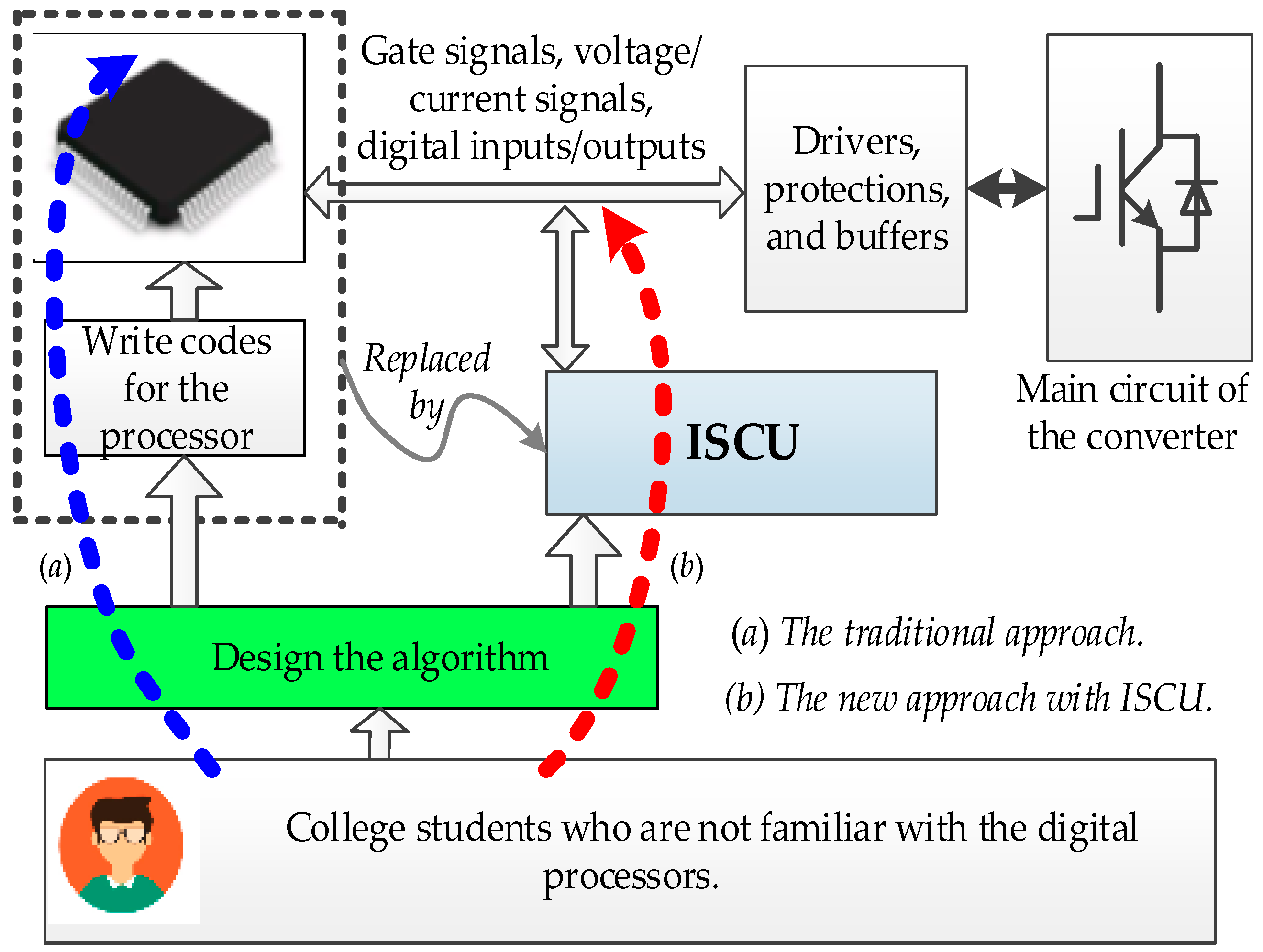
The ISCU is made up of two components, which are the control board and computer software.
(1)
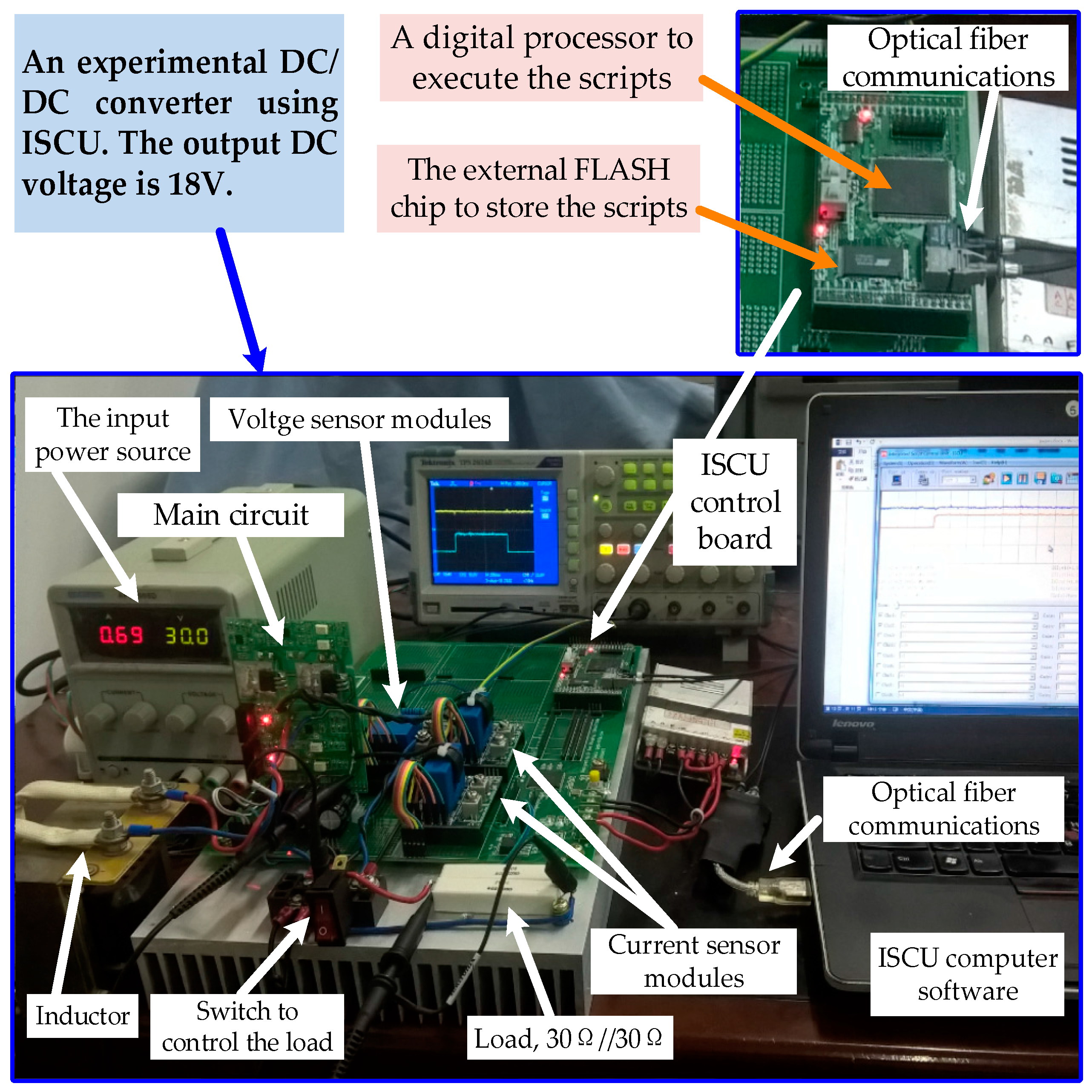
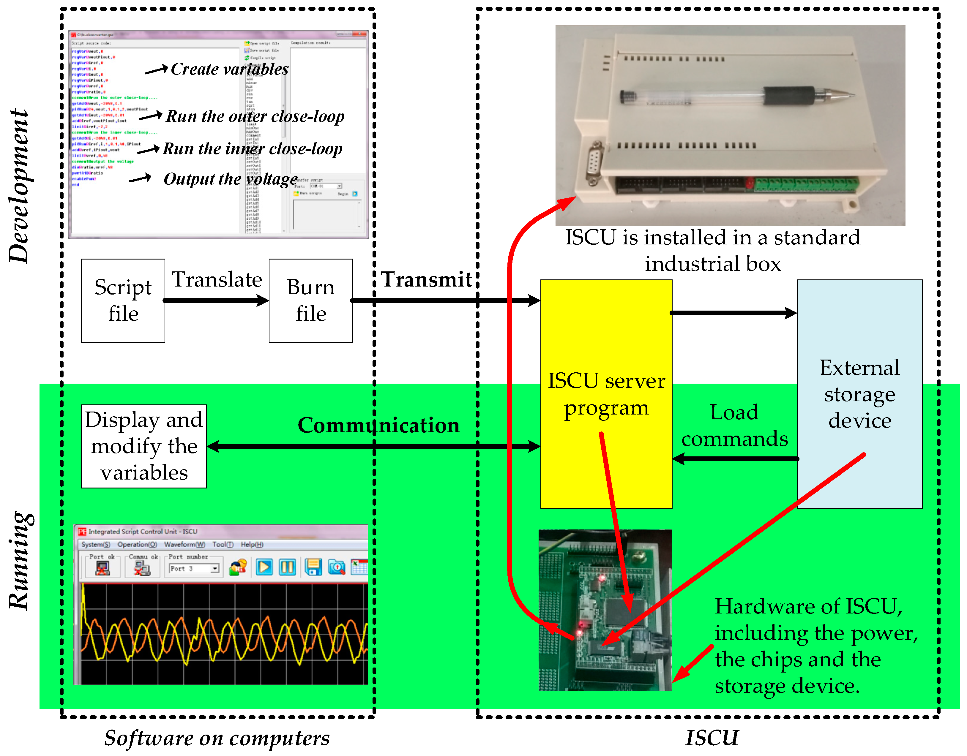
The control board is based on a digital processor. It has the necessary interfaces to control the converter, for example, analog-to-digital ports, digital input/output ports and PWM ports. On the control board, there is an external storage chip, in which the scripts are stored. The digital processor will load the scripts in the storage chip and execute them when power up.
(2)
The computer software provides environment for the users to write scripts and save them into the storage chip on the control board. Also, it can show that the waveforms of the variables defined in the scripts by the user. Figure 2 shows the structure of ISCU.

2.2. The Hardware Platform

The control board has a number of digital and analog interfaces for the applications. Also, the control board provides an external data bus for further expansion. Figure 3 shows the picture of the experimental platform using ISCU. The computer and the control board are connected by a pair of optical fiber.

2.2.1. Resources and Supporting Functions

The control board of ISCU is shown in Figure 4.
As we can see, there are a digital processor and an external FLASH chip on the board. Apart from these two core chips, a number of terminals make up the necessary interfaces, which sends the control signals between the processor and the converters. The whole resources on the control board and their supporting functions are listed in Table 1. A server program resides in the processor on the board. When powering up, the program will read the scripts in the storage chip and execute the scripts in every switching period.

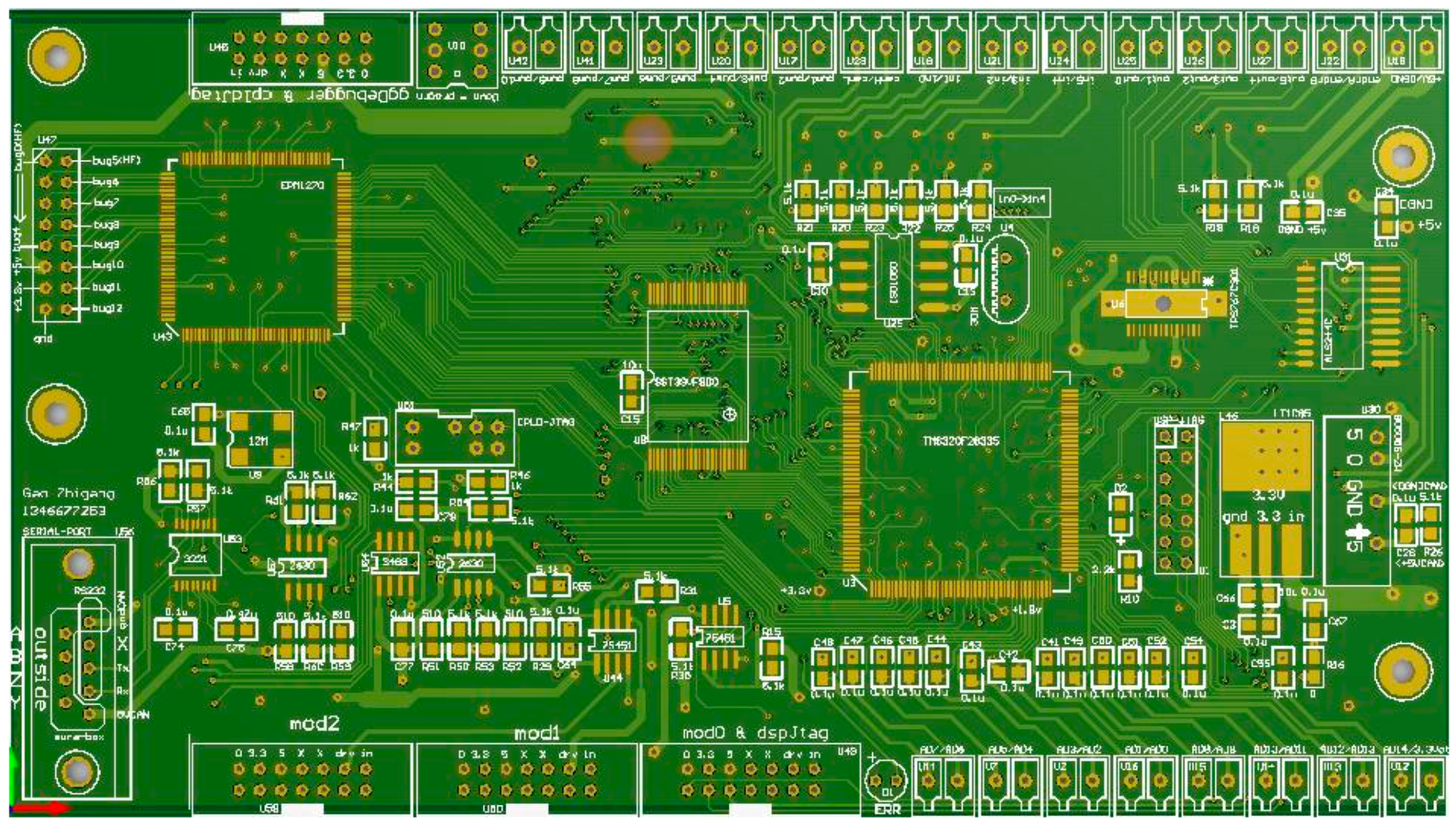
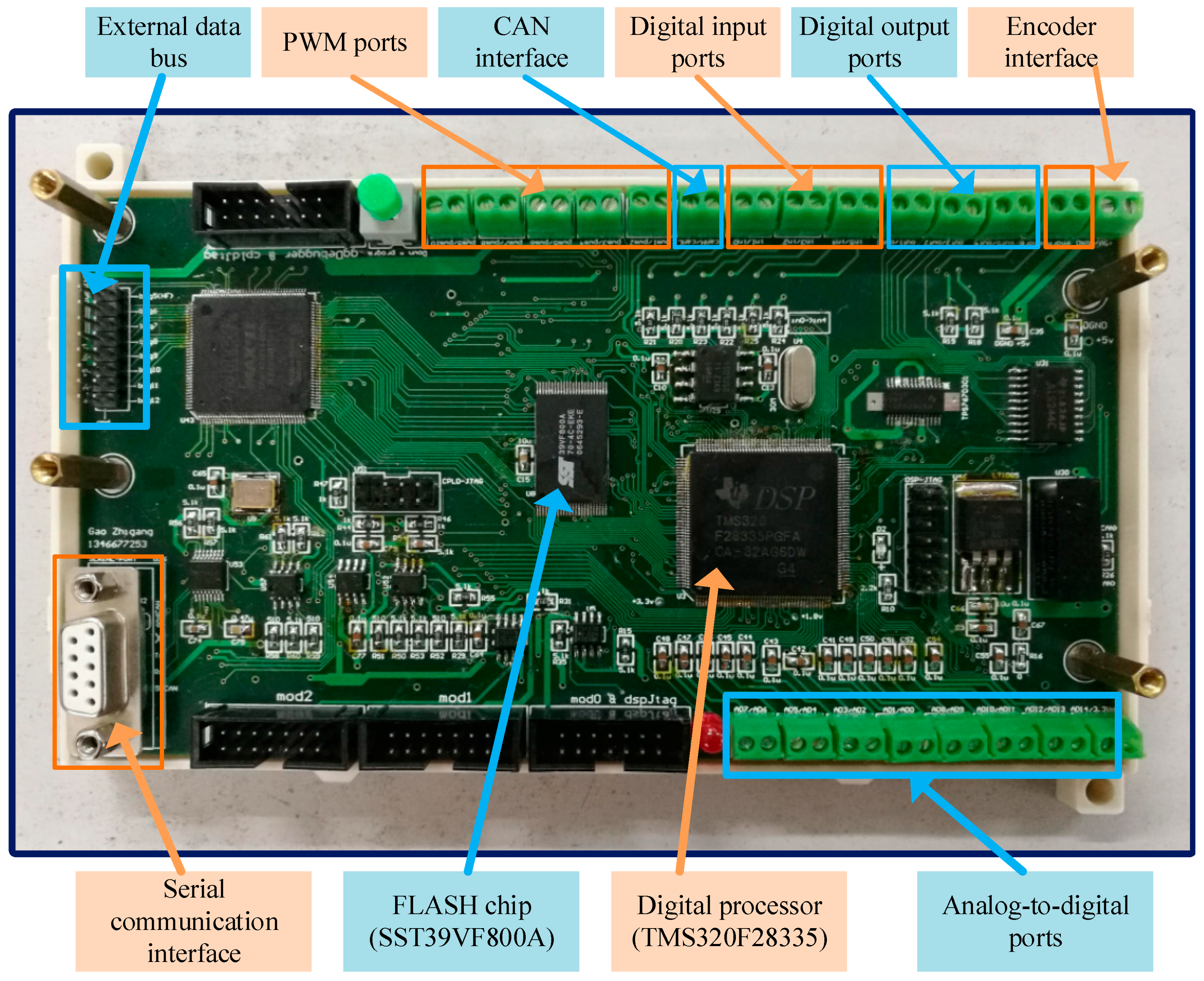
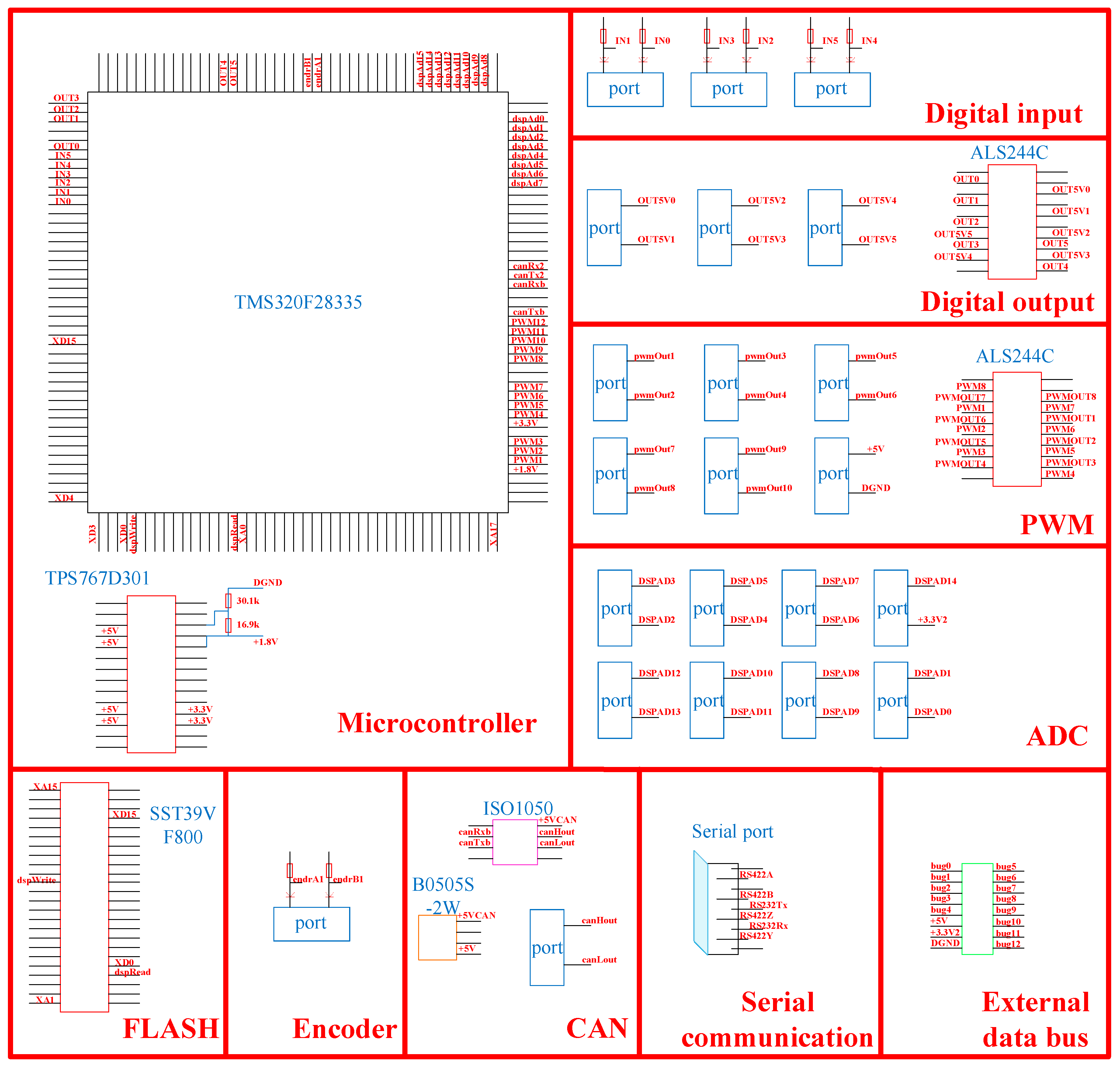
2.2.2. Schematic and Layout Diagrams

The major units of the schematic diagram for ISCU are shown in Figure 5.
The microcontroller unit is composed of a DSP-F28335 chip and a TPS767D301 chip, which is used to provide both 3.3 V and 1.8 V for the DSP chip as a dual voltage regulator. In the digital output unit and PWM unit, SN54ALS244C chips are used to memorize the state of signals from the DSP chip. The ISO1050 works as a galvanically isolated CAN transceiver in the CAN unit, while the power comes from a DC/DC converter, which is the B0505S chip. The other resources in Figure 5 are all interfaces with various functions.
As for the layout diagram of ISCU, the interfaces are designed on the edges of the control board, while the other components are placed in an orderly manner, as shown in Figure 6. The well-designed control board can be installed in a standard industrial box. Users just need to focus on the interfaces they will use, which is quite convenient and easy to operate.

2.2.3. “Why Selected” Discussion

All of the resources and components on the control board are selected based on the consideration of proper size, economic, and most importantly, the supporting functions ISCU need to realize.
  • TMS320F28335 DSP chips, one kind of Texas Instruments C2000 microcontrollers, are widely used in many industrial fields with the advantages of high precision, low cost, small power consumption, and high peripheral integration. In order to validate algorithms for converters in power electronic education, the digital processor of ISCU need to have powerful abilities of controlling and signal processing. Given the considerations mentioned above, a DSP-F28335 chip is used as the digital processor.
  • SST39V800A devices are 512 K × 16 CMOS Multi-Purpose Flash with high performance CMOS Super flash technology. They are suited for applications that require convenient and economical updating of program, configuration, or data memory. Using such a device as an external FLASH chip on the control board makes it possible to store all the data transmitted from the burn file before being loaded and executed.
  • All of the terminals are designed to form relevant signal transmission paths between the control board and the computer or the converters. They are all economical and widely used in industrial applications. It is proved that they all can ensure high precision of transmitting signals.

2.3. The Computer Software

Basically, the computer software has two pages, as shown in Figure 7. The first page is used to edit, compile and transfer the scripts to the control board. The second page is used to observe the waveforms of the variables created in the scripts by the user. The software supports as much as 104 commands, which are about mathematical operations, judgments, communications, regulators, and so forth. The users can write scripts to realize specific functions and observe the variables in the software. Figure 7 also shows an example about how to create a 10 Hz square waveform and output it. In the scripts, “ifLarger/but/overIf” is used to change the value of variable “counter” and control the digital output port.

3. Script Systems in ISCU

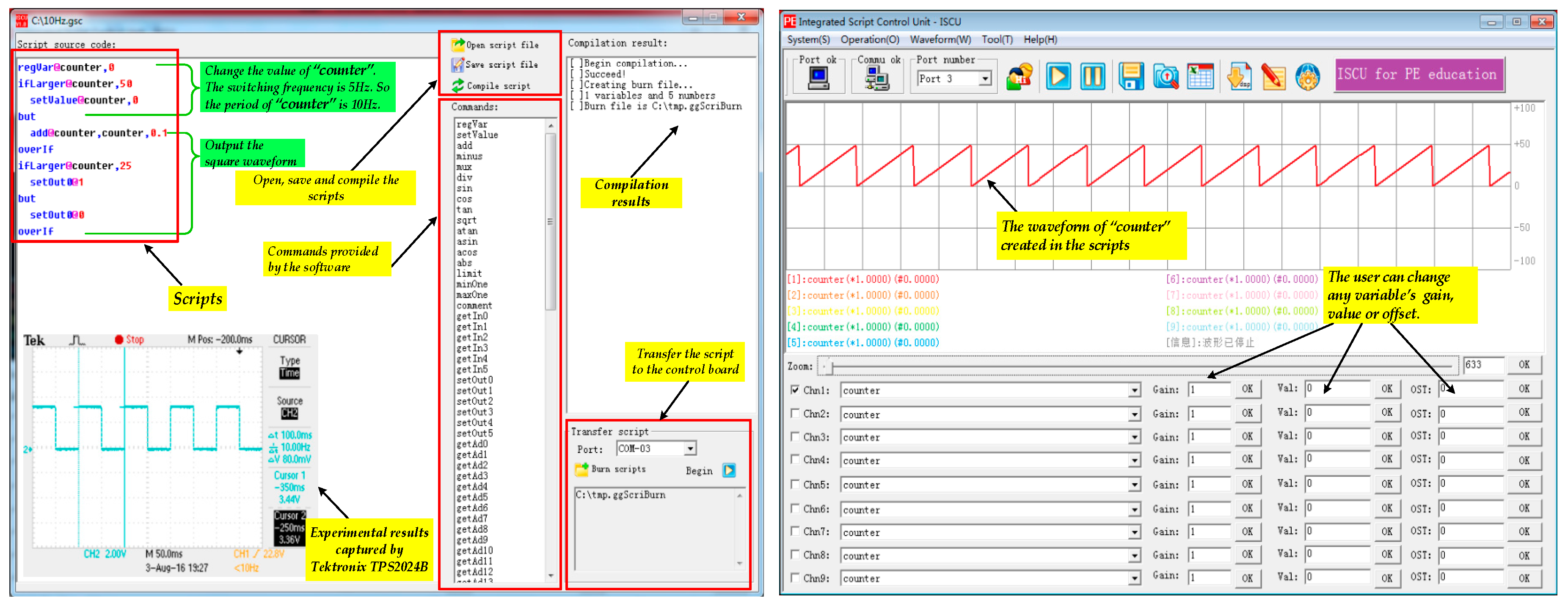
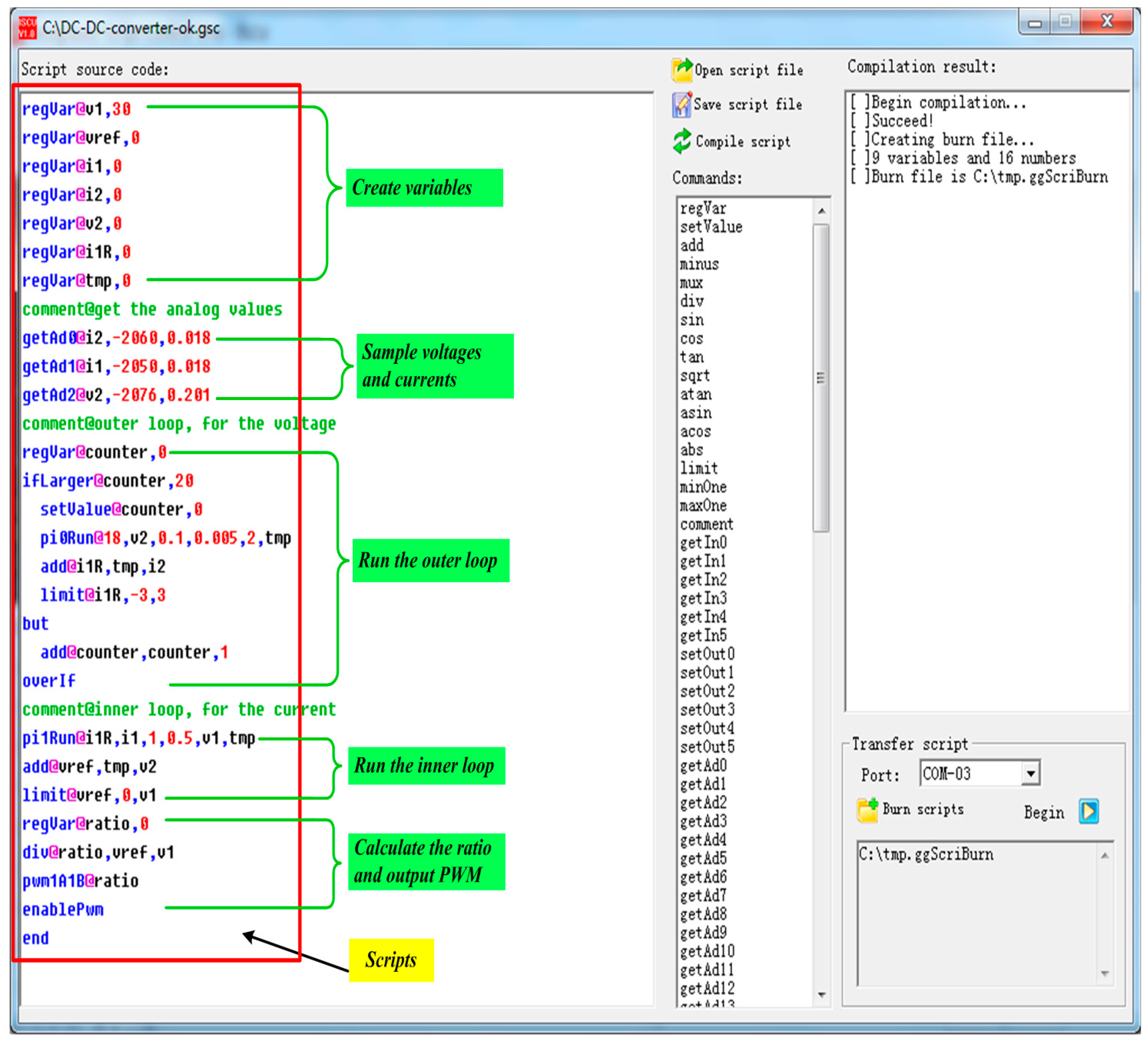
3.1. Commands and the Classification

The script system can compile the scripts written by the user and find the mistakes. If the scripts are compiled successfully, then they can be transferred to the control board. The users can create variables in these scripts and call the commands provided in the script system. The 104 commands can be divided into five groups, as shown in Table 2. With the commands provided, the user can design any kinds of algorithm and make the control board work in the expected mode.

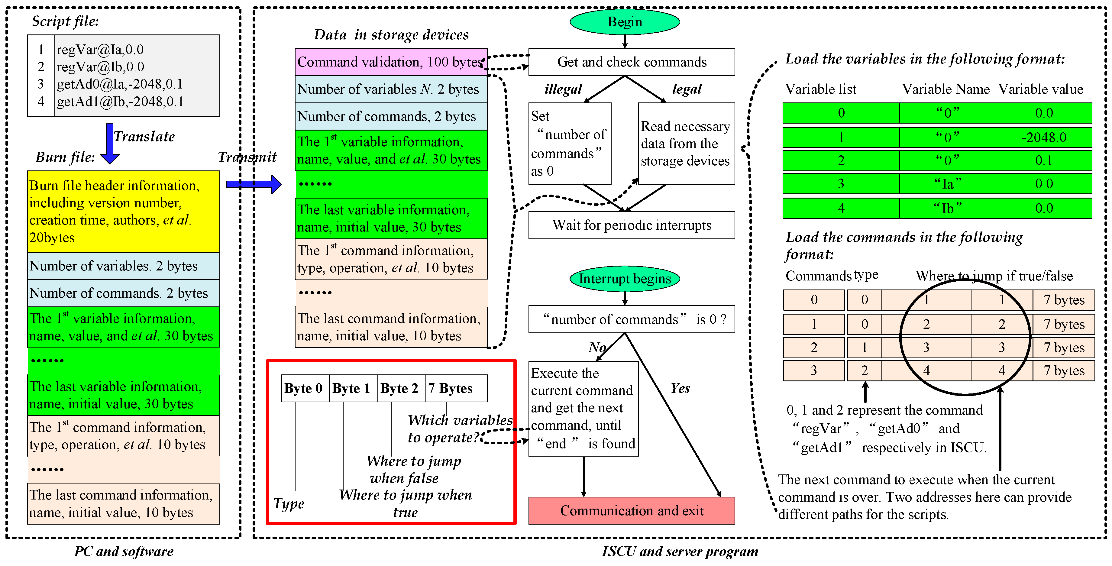
3.2. The Compilation and Storage for the Scripts

The compiler works in the followings steps:
  • Divided the scripts into a number of pieces.
  • The compiler tries to find the commands and the parameters for each piece. If the format is not correct or the parameters are not available, the compilation will fail.
  • Record the variables created by the user. Every variable is stored in 30 bytes, 26 of which are about the variable name. The last 4 bytes are about the initial value of the variable.
  • Record each piece into 10 bytes, which are used to store the command type, the parameters and the logic information.
Hence, if the number of the variables is m and the number of the pieces is n, the number of the bytes (denoted by q) used to store the script can be calculated as:
q = 30 m + 10 n

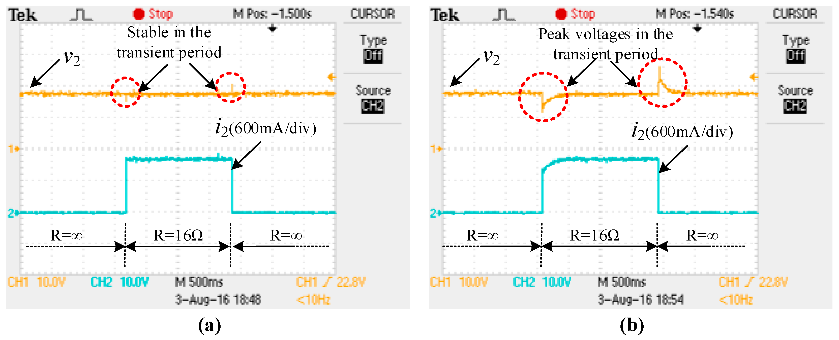
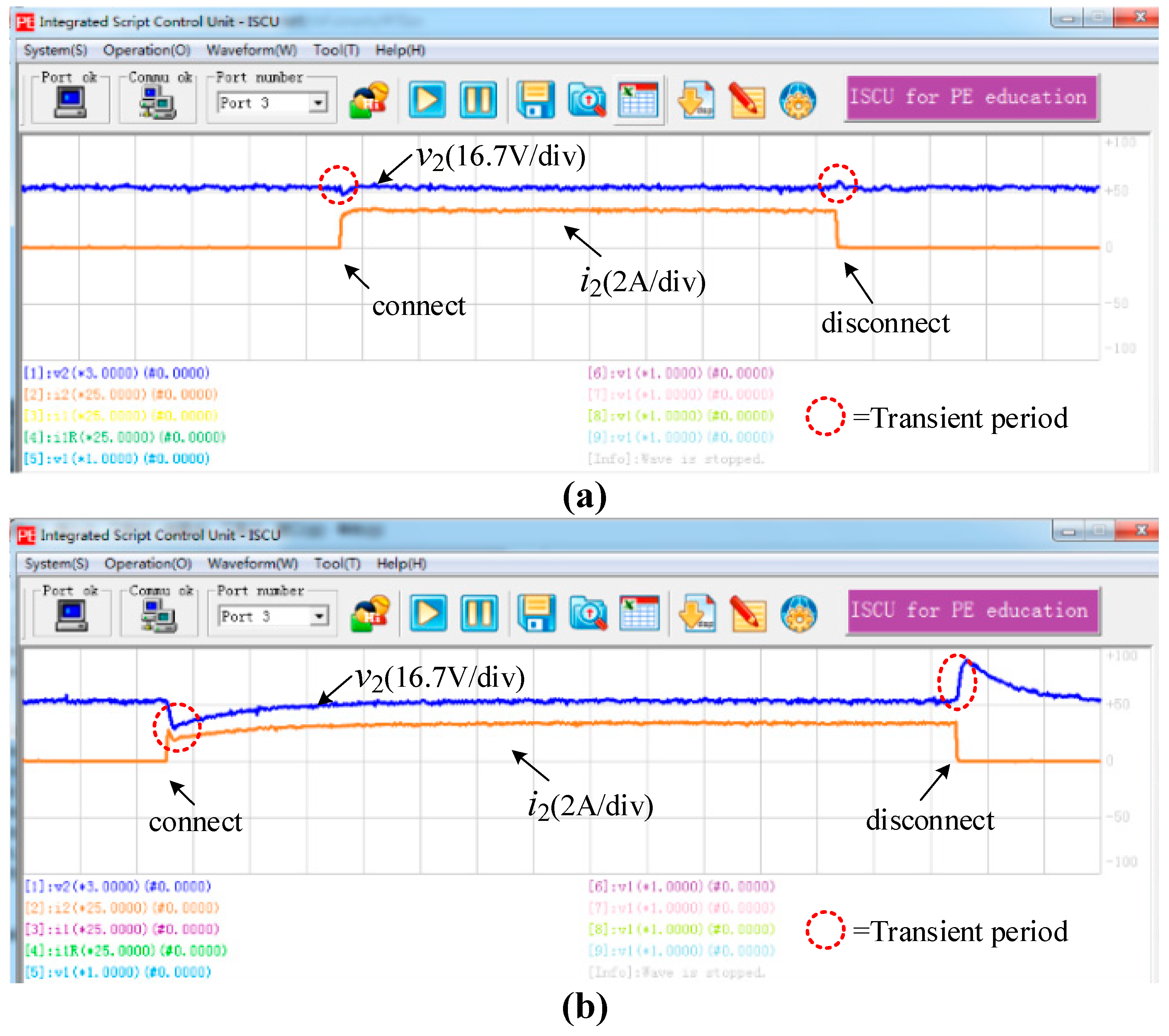
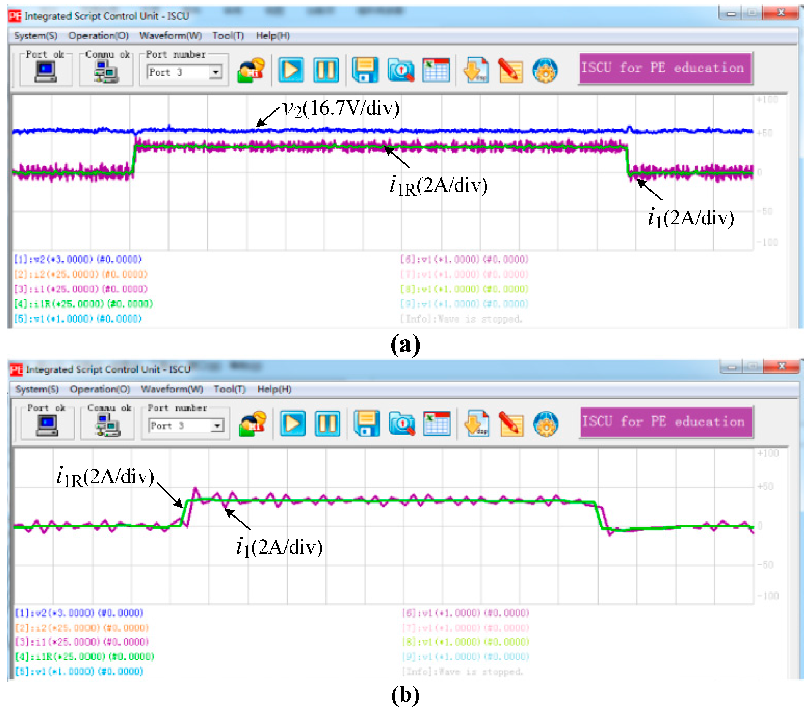
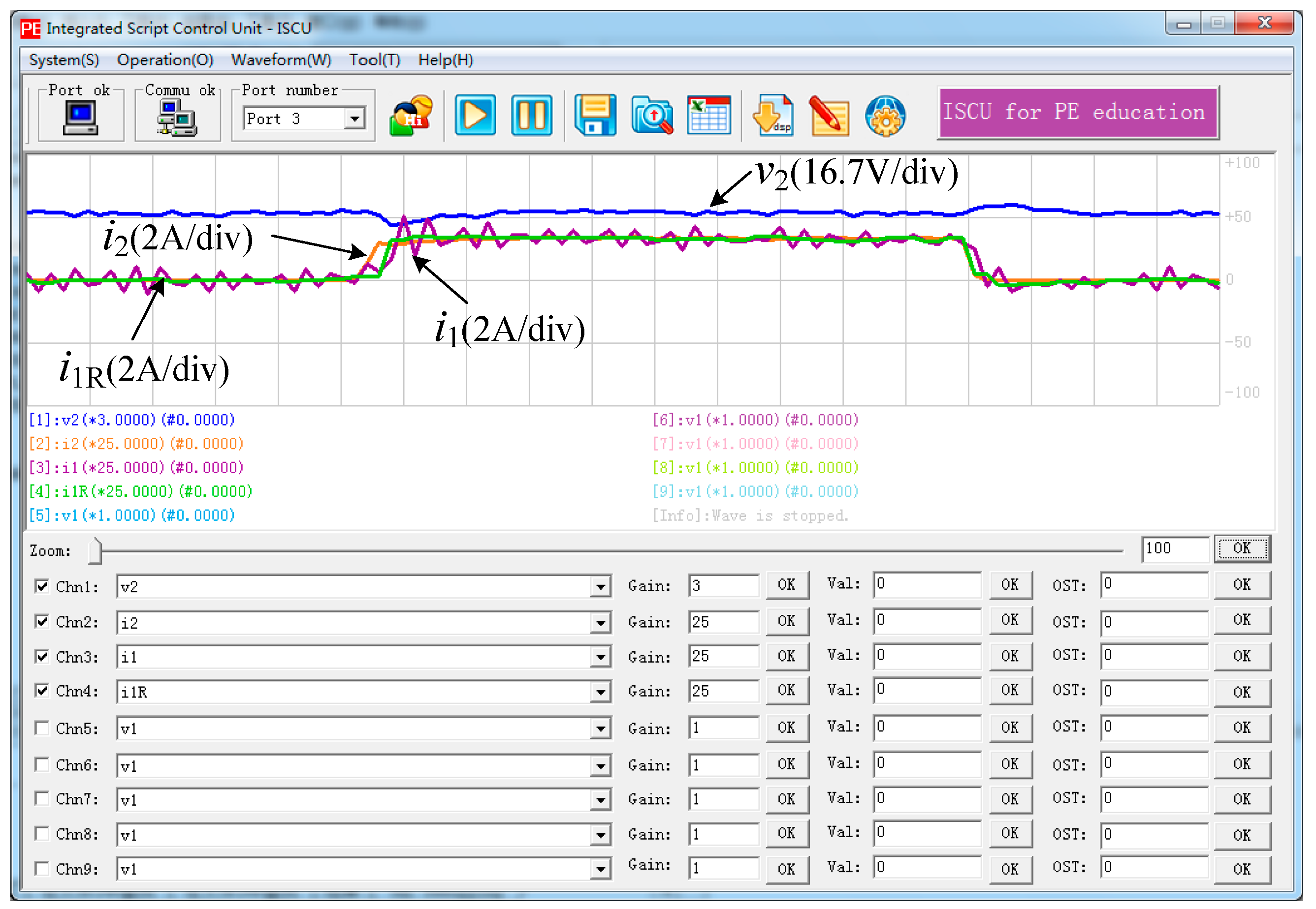
4. Experimental Results and Analysis

Bi-directional DC-DC converters can be alternately operated as step down converters in one direction of energy flow and as step up converters in reverse direction of energy flow [20]. Thus, they are widely used in hybrid vehicles, energy storage systems, and energy conversion systems, and so forth [21,22,23,24,25,26].
This paper also builds a bi-directional DC-DC converter to validate the ISCU. The topology of the converter is shown in Figure 8. The photo of the experimental prototype is shown in Figure 3. The input voltage is DC 20~30 V, and the converter can output DC 18 V.
The equations of the bi-directional DC-DC converter can be written as (2) and (3):
C d v 2 d t = i 1 i 2
L d i 1 d t = v r e f v 2
The definitions of all the symbols such as v1, i1, and i2, are described in Figure 8.
The control scheme is also shown in Figure 8. The inner loop is to control the current i1 on the inductor. The outer loop is to control the output voltage v2. From (2), v2 can be controlled by maintaining (i1i2), thus a feed-forward strategy is used. The combination of voltage-current close loop control and current feed-forward control can not only track the reference signals, but also improves the load disturbance regulation characteristics when the load current changes [27,28,29,30,31].
The scripts for the control algorithm are shown in Figure 9. All of the variables defined in Figure 8 are created in the scripts. The codes can be divided in to five parts.
The parameters of the prototype is shown in Table 3. The power consumed by the load can be calculated as 18 × 18/16 = 20.25 W.
The output voltage and current are shown in Figure 10a when the control algorithm in Figure 8 is adopted. The output voltage v2 is kept to be 18 V. When the resistor is on, the current is 1.1 A, which coincides with the theoretical analysis. Also, when the load is changed rapidly, v2 is kept stable, indicating that the performance of the system is high. When the feed-forward path is not used, the experimental results are shown in Figure 10b. When the load is changed, the voltage v2 is also changed and after a short time, v2 is kept to be 18 V again. The two comparative pictures in Figure 10 validate the good performance of the converter.
The output voltage and current can also be observed by the computer software because both of them are sampled and the variables are v2 and i2, as shown in Figure 11.
With ISCU, it is possible to monitor all of the variables and thus the debugging of the algorithm is simplified. Figure 12a shows the reference current i1R and the sampled current i1. The zero-error tracking is realized. Figure 12b shows the two curves in a shorter period than Figure 12a. The sampled current is around the reference current. Thus, the current on the inductor is under control and the current loop works well.
Figure 13 shows the three current i1R, i1 and i2 together. It explains the working principles of the feed-forward strategy described in Figure 7. When the load is on, the current i2 rises rapidly. The i1R also goes higher because of (2). When the load is off, the current i2 falls rapidly. The i1R also goes lower. In this way, the transient period is shortened and the output voltage is kept stable.
The efficiency of the converter is tested using different input voltages, as shown in Figure 14. The open circuit power loss of the converter rises when the input voltage is higher. The efficiency of the system is basically above 80%. The peak efficiency is around 96%, and it appears when the input voltage is 30 V.

5. ISCU Used in Class and in Industrial Applications

In order to estimate the ISCU, ten students in Grade 3 in our university are selected in class to study the ISCU and later, they are required to accomplish five tasks in 1 hour. The five tasks are:
  • Generate the required PWM signals.
  • Sample the required analog signals.
  • Get the digital input signals.
  • Output digital signals.
  • Generate the required sinusoidal PWM signals.
The result shows that after a one-hour training, all of the students can finish the above tasks with ease, indicating that they have gained the necessary abilities to build the control system for a power electronic converter. Figure 15 shows the application, which is the combination of ISCU and an industrial inverter. The inverter was controlled by the board on which a DSP-F28335 chip was employed to realize the algorithms. It is difficult to develop DSP programs and realize the algorithms for the beginners. Instead, the ISCU is introduced to replace the DSP chip and it provides a much easier way for the implement of the algorithm.
Figure 16 shows the complementary gate signals generated by ISCU. Figure 16a verifies that the switching frequency is 5 kHz. Figure 16b shows the dead band on the rising edge and falling edge.
Figure 17 shows the three-phase currents on the load. In Figure 16a, it can be found the period is 20 ms and the currents are sinusoidal. Figure 16b shows the details of the currents. The period of the current ripple is 100 μs. The experimental results show that the ISCU can be used to control the three-phase inverter easily and quickly for the students.

6. Working Schemes and Open Source Plan

The working schemes of ISCU can be described in Figure 18. The users can write the scripts, translate the scripts, and transmit the burn file to ISCU in the development period. Then the users can observe and change the variables when ISCU is running.
The server program runs in ISCU to realize all of the functions, such as loading the commands from the storage devices and doing the communications. It executes the commands one piece after another. Figure 19 shows the data flow among the script file, the burn file, and how the server program execute the commands.
In Figure 19, the software developed for ISCU translates the script file into the burn file. During this stage, the software will collect all of the variables declared in the scripts file and find the grammar errors (For example, spelling mistakes, not-declared variables, and et al.) if there are. The burn file will be transmitted to ISCU and the data will be stored into the storage devices partly. As shown in Figure 19, the numbers of the variables and the commands will be stored firstly. Each variable consists of 30 bytes, which are the name (26 bytes) and the value (4 bytes). There are 10 bytes for each command. The first three bytes are about the type and the command to execute when the current command is true/false. The last seven bytes are about the variables to operate. The ISCU server program will execute the commands according to the type.
Figure 19 also shows the management of the variables and commands in ISCU. All of the constant numbers and variables are stored in the list and there is a unique index for each one.
The authors would like to open all of the documents and source codes about ISCU to the society. The authors are happy to share the details with anyone who are interested in the system. Currently, three ways are provided to obtain the material about ISCU:
  • Visit the open source library—github, and find the open documents in https://github.com/luckyharrybit/ISCU. After clicking the link, two folders named “Software and Codes” and “hardware-board” respectively could be found.
  • The authors are applying for a website witch will displays all source codes. Once it’s accomplished, the information will be updated and announced in the project in github.
  • Contact the authors by the following e-mails: [email protected] or [email protected].
It is believed that with the help of ISCU, the college students will benefit not only when they are studying the power electronics, but also when they are building a converter and writing the algorithm. Any modifications and improvements about the ISCU are welcomed and encouraged. It is very essential since the limitations of ISCU also exist. Some relevant improvement measures are proposed.
Firstly, since the approaches to obtain the source codes and documents for ISCU have been given out, the daily maintenance of e-mails and websites will meet challenges. Thus, volunteers are needed to help with the maintenance on one hand. On another hand, a forum will be added on the website the authors are applying. In such case, those who are interested in ISCU could communicate with each other on the website.
Secondly, given that ISCU must be a low cost tool, certain chips and components are selected on the hardware platform, such as the DSP-F28335 chip. Hence, the switching frequency is decided in a certain range, which should be less than 20 kHz. In that way, it is not possible to run or execute a very complicated algorithm by ISCU. However, users could make changes about ISCU, such as the microcontroller, after reading the whole open sources.

7. Comparison with Other Toolboxes

With conventional methods, some commercialized toolkits may have been applied in the relevant situations, such as LABVIEW, MATLAB, PSIM, Saber, dSPACE, and et al.
The most remarkable characteristics of LABVIEW are graphical programming and data flow driving. The source code is replaced by all block diagrams. However, it cannot realize real time control since it is a top-level toolkit. As for MATLAB, its toolboxes combined with A/D interfaces are mostly applied in data collection or instrument control system [32]. Users of these two toolkits have to firstly design the host computer interface according to the functions remained to achieve. However, it takes a long time to learn the grammar and logic relationships. Besides, LABVIEW or MATLAB just provides programming environment for users. To validate the prototypes and achieve the whole functions, a hardware platform should be established personally or a data collection board should be properly chosen.
PSIM and Saber are also widely used in the simulation of power electronic circuits [33,34]. Users could generate control algorithm codes by using basic logic components or loading dll (dynamic link library) files, and then the algorithm will be validated. These two softwares are both easy to operate. However, they just provide simulation and programming environment. It is not possible to validate a prototype without hardware platform. Besides, the prices of them are both around $600.
dSPACE is one set of platform comprised of software and hardware, which can eliminate the process of designing the relevant PCB boards [35,36]. The hardware system consists of a digital processor and abundant I/O interfaces, and the software system involves the whole toolkits for automatic generation, load, execution, and debugging of the source codes. With dSPACE, users just need to concentrate on the control strategy, while the rest of processes, such as off-line and real-time simulation, can be implemented automatically by its toolkits. Nevertheless, users must adapt the customized hardware boards that cost about €4000, i.e., $4732. It is expensive for the experiments in power electronics education, and the maintainability is poor.
Comparing with the toolboxes mentioned above, the ISCU has the advantages of easy to learn, convenient for power electronic experiments, high reliability and maintainability. Since it is also made up of both a control board and a computer software, the structure and principles is similar to the dSPACE to some extent. However, ISCU is economical free, and the source codes are open to the public. The users can modify ISCU and add new features on it. The details of the comparison is listed in Table 4.

8. Conclusions

An integrated script control unit, named as ISCU, is proposed and invented to assist the power electronics educations for the college students. With ISCU, the college students can implement a power electronic converter without any digital processor experience. Other designers and engineers can also develop algorithms quickly with the help of ISCU. The ISCU provides a set of commands to meet the requirements for converters. A bi-directional DC-DC converter is built with ISCU to validate the performance. Only a small number of scripts are needed to implement the close-loop control algorithm with load current feed-forward compensation. The efficiency is tested and it can be as high as 96%. A three-phase inverter for industrial applications is also established based on ISCU. A trial about the ISCU is accomplished in class, showing that it is easy to learn and master. The ISCU is useful for the power electronics educations and can improve the efficiency in power electronic device developments.

Acknowledgments

This work is supported by the National Natural Science Foundation of China under Project 51207010, and also by the International S&T Cooperation Program (ISTCP) of Beijing Institute of Technology through Grant GZ2016065101. ISCU has been test and used by Beijing Unison Electronics Technology Co. Ltd. (Stock code: 871189, China) in energy storage systems. ISCU will be used to assist the power electronics education in class for under graduate students in Beijing Institute of Technology from 2018.

Author Contributions

Zhigang Gao put forward the main idea, designed the entire ISCU, guided the experiments and wrote the first version manuscript. Qi Lu performed the experiments, collected the data and prepared some sections of the manuscript.

Conflicts of Interest

The authors declare no conflict of interest.

References

  1. Tomczewski, K.; Wrobel, K. Quasi-three-level converter for switched reluctance motor drives reducing current rising and falling times. IET Power Electron. 2012, 5, 1049–1057. [Google Scholar] [CrossRef]
  2. Sangshin, K.; Hamid, A.T. A hybrid converter system for high performance large induction motor drives. IEEE Trans. Energy Convers. 2005, 20, 504–511. [Google Scholar]
  3. Jin, Y.; Ali, E. Power electronic converters for 12/8 switched reluctance motor drives: A comparative analysis. In Proceedings of the 2014 IEEE Transportation Electrification Conference and Expo (ITEC 2014), Dearborn, MI, USA, 15–18 June 2014; pp. 1–6. [Google Scholar]
  4. Piotr, B. Power electronic converters in DC microgrid. In Proceedings of the 2007 Compatibility in Power Electronics (CPE 2007), Gdansk, Poland, 29 May–1 June 2007. [Google Scholar]
  5. Zhenhua, J.; Lijun, K.; Roger, A.D. Flexible multiobjective control of power converter in active hybrid fuel cell/battery power sources. IEEE Trans. Power Electron. 2005, 20, 244–253. [Google Scholar]
  6. Rui, L.; Dianguo, X. Parallel operation of full power converters in permanent-magnet direct-drive wind power generation system. IEEE Trans. Ind. Electron. 2011, 60, 1619–1629. [Google Scholar]
  7. Md, A.; Liuchen, C. Reliability comparison of power electronic converters used in grid-connected wind energy conversion system. In Proceedings of the 2012 IEEE 3rd Power Electronics for Distributed Generation Systems (PEDG 2012), Aalborg, Denmark, 25–28 June 2012; pp. 323–329. [Google Scholar]
  8. Lari, N.; Joonas, P.; Anssi, M.; Tuomas, M.; Juha, H.; Juha, J.; Jukka, V.; Diego, T.L.; Seppo, V.; Teuvo, S. Photovoltaic generator as an input source for power electronic converters. IEEE Trans. Power Electron. 2013, 28, 3028–3038. [Google Scholar]
  9. Yi, D.; Ronald, G.H. Space-vector versus nearest-level pulse width modulation for multilevel converters. IEEE Trans. Power Electron. 2015, 30, 2962–2974. [Google Scholar]
  10. Xinyu, W.; Jinjun, L.; Shaodi, O.; Fei, M. Research on unbalanced-load correction capability of two power electronic transformer toplogies. IEEE Trans. Power Electron. 2015, 30, 3044–3056. [Google Scholar]
  11. Emanuel, S.; Cosmin, P.; Martin, O. Islanding detection search sequence for distributed power generators under AC grid faults. IEEE Trans. Power Electron. 2015, 30, 3106–3121. [Google Scholar]
  12. Dehong, Z.; Jin, Z.; Yang, L. Predictive torque control scheme for three-phase four-switch inverter-fed induction motor drives with DC-link voltages offset suppression. IEEE Trans. Power Electron. 2015, 30, 3309–3318. [Google Scholar]
  13. Zhengwei, L.; Xiyou, C. TMS320F28335 based phase-shift full-bridge ZVS DC/DC converter. Convert. Tech. 2012, 34, 60–61. [Google Scholar]
  14. Nalin, L.G.; Santanu, M.; Kapil, J. An inductor current sensing technique for digital controllers. In Proceedings of the 2014 IEEE 40th Industrial Electronics Society (IECON 2014), Dallas, TX, USA, 29 October–1 November 2014; pp. 4171–4177. [Google Scholar]
  15. Florian, B.; Ruwan, P.S.C.; Farhad, S.; Sumedha, R.; Arindam, G. Application notes and recommendations on using TMS320F28335 digital signal processor to control voltage source converters. In Proceedings of the 2014 Australasian Universities Power Engineering Conference (AUPEC 2014), Perth, Australia, 28 September–1 October 2014. [Google Scholar]
  16. Hongjun, C.; Kai, F.; Hao, X.; Kai, D. Implementation of hybrid control for bi-directional DC-DC converter. In Proceedings of the 2014 IEEE 4th Cyber Technology in Automation, Control, and Intelligent Systems (CYBER 2014), Hong Kong, China, 4–7 June 2014; pp. 669–674. [Google Scholar]
  17. Mor, M.P.; Shmuel, B.Y. Digital control of resonant converters: Resolution effects on limit cycles. IEEE Trans. Power Electron. 2010, 25, 1652–1661. [Google Scholar]
  18. Wajiha, S.; Hrishikesh, N. DSP-based control for reliable fuel cell power systems with input ripple current compensation. In Proceedings of the 2008 IEEE Power and Energy Society General Meeting—Conversion and Delivery of Electrical Energy in the 21st Century, Pittsburgh, PA, USA, 20–24 July 2008. [Google Scholar]
  19. Subramanya, B.; Nagaraja, H.N. A novel DSP based non inverting buck-boost converter for PV system. In Proceedings of the 2015 IEEE Signal Processing, Informatics, Communication and Energy Systems (SPICES), Kozhikode, India, 19–21 February 2015. [Google Scholar]
  20. Manisha, S.; Jil, S.; Chirag, C. Design, simulation and implementation of two phase interleaved bi-directional DC-DC converter. In Proceedings of the 2015 IEEE Electrical, Electronics, Signals, Communication and Optimization (EESCO), Visakhapatnam, India, 24–25 January 2015. [Google Scholar]
  21. Xiaoyu, J.; Dehong, X.; Shuailin, D.; Changsheng, H. A high power density and efficiency bi-directional DC/DC converter for electric vehicles. In Proceedings of the 2015 IEEE 9th Power Electronics and ECCE Asia (ICPE-ECCE Asia), Seoul, Korea, 1–5 June 2015; pp. 874–880. [Google Scholar]
  22. Manu, J.; Praveen, K.J.; Matteo, D. Analysis of a bi-directional DC-DC converter topology for low power application. In Proceedings of the 1997 IEEE Electrical and Computer Engineering, Saint Jonas, NL, Canada, 25–28 May 1997; pp. 548–551. [Google Scholar]
  23. Shengyen, L.; Li, W.; Teming, L.; Anton, V.P. Integration of wind power and wave power generation systems using a DC microgrid. IEEE Trans. Ind. Appl. 2015, 51, 2753–2761. [Google Scholar]
  24. Shigenori, I.; Hirofumi, A. A bi-directional DC/DC converter for an energy storage system. In Proceedings of the 2007 IEEE 22nd Applied Power Electronics Conference (APEC 2007), Anaheim, CA, USA, 25 February–1 March 2007; pp. 761–767. [Google Scholar]
  25. Huafeng, X.; Donghua, C.; Shaojun, X. A ZVS bi-directional DC-DC converter for high-low voltage conversion. In Proceedings of the 2005 IEEE 31st Industrial Electronics Society (IECON 2005), Raleigh, NC, USA, 6–10 November 2005; pp. 1154–1158. [Google Scholar]
  26. Zahra, A.; Sheldon, S.W. Digital control of a bidirectional DC/DC switched capacitor converter for hybrid electric vehicle energy storage system applications. IEEE Trans. Smart Grid 2014, 5, 158–166. [Google Scholar]
  27. Qinglin, Z.; Yunhua, X.; Xiaoyi, J.; Weiyang, W.; Lingling, C. DSP-based closed-loop control of bi-directional voltage mode high frequency link inverter with active clamp. In Proceedings of the 2005 IEEE 14th Industry Applications Conference (IAS 2005), Kowloon, China, 2–6 October 2005. [Google Scholar]
  28. Rajesh, K.T. Close loop control analysis with feed-forward control of Cuk converter. In Proceedings of the 2014 IEEE India Conference (INDICON 2014), Pune, India, 11–13 December 2014; pp. 928–933. [Google Scholar]
  29. Lijun, J.; Guangyao, Y.; Miaomiao, J.; Yifan, C.; Haipeng, Z.; Ke, Z. Study of bi-directional DC-DC converter of micro-grid hybrid energy storage system. In Proceedings of the 2015 IEEE 10th Industrial Electronics and Applications (ICIEA 2015), Auckland, New Zealand, 15–17 June 2015; pp. 1166–1169. [Google Scholar]
  30. Amirnaser, Y. Control of an islanded distributed energy resource unit with load compensating feed-forward. In Proceedings of the 2008 IEEE Power and Energy Society General Meeting, Pittsburgh, PA, USA, 20–24 July 2008. [Google Scholar]
  31. Yonggao, Z.; Liming, L.; Pengcheng, Z.; Xiaoyuan, L.; Yong, K.; Yanli, G. Double closed loop control and analysis for shunt inverter of UPFC. In Proceedings of the 2005 IEEE Electrical Machines and Systems (ICEMS 2005), Nanjing, China, 27–29 September 2005; pp. 1118–1123. [Google Scholar]
  32. Wenjuan, H.; Hui, L.; Yu, W.; Yu, G. The design and simulation of a teachingvirtual platform by combining LABVIEW and Simulink for undergraduates of Electrical Engineering. In Proceedings of the 2017 IEEE 20th Electrical Machines and Systems (ICEMS 2017), Sydney, Australia, 11–14 August 2017. [Google Scholar]
  33. Jin-Hyuk, P.; Hae-Gwang, J.; Kyo-Beum, L. Output current ripple reduction algorithms for home energy storage systems. Energies 2013, 6, 5552–5569. [Google Scholar]
  34. Haoping, Y.; Tao, W. Derating design for power supply module based on saber simulation. In Proceedings of the 2016 IEEE Prognostics and System Health Management Conference (PHM-Chengdu 2016), Chengdu, China, 19–21 October 2016. [Google Scholar]
  35. Batunlu, C.; Alrweq, M.; Albarbar, A. Effects of Power Tracking Algorithms on Lifetime of Power Electronic Devices Used in Solar Systems. Energies 2016, 9, 884. [Google Scholar] [CrossRef]
  36. Morfin, O.A.; Castañeda, C.E.; Valderrabano-Gonzalez, A.; Hernandez-Gonzalez, M.; Valenzuela, F.A. A Real-Time SOSM Super-Twisting Technique for a Compound DC Motor Velocity Controller. Energies 2017, 10, 1286. [Google Scholar] [CrossRef]
Figure 1. Concept of the proposed integrated script control unit (ISCU).
Energies 10 01802 g001
Figure 2. The structure of ISCU.
Energies 10 01802 g002
Figure 3. The photo of the experimental platform using ISCU.
Energies 10 01802 g003
Figure 4. The control board of ISCU.
Energies 10 01802 g004
Figure 5. Schematic diagram of ISCU.
Energies 10 01802 g005
Figure 6. The layout figure of ISCU control board.
Energies 10 01802 g006
Figure 7. Appearances of the computer software.
Energies 10 01802 g007
Figure 8. Topology and control scheme of the bi-directional DC-DC converter.
Energies 10 01802 g008
Figure 9. Topology and control scheme of the bi-directional DC-DC converter.
Energies 10 01802 g009
Figure 10. Experimental waveforms of the voltage and current. (a) Use the control diagram in Figure 8; (b) Without feed-forward compensation.
Energies 10 01802 g010
Figure 11. Waveforms of the variables v2 and i2. (a) Use the control diagram in Figure 8; (b) Without feed-forward compensation.
Energies 10 01802 g011
Figure 12. Waveforms of the variables v2 and i2. (a) Use the control diagram in Figure 7; (b) Without feed-forward compensation.
Energies 10 01802 g012
Figure 13. The observation of the feed-forward strategy.
Energies 10 01802 g013
Figure 14. The curves of the system efficiency.
Energies 10 01802 g014
Figure 15. Application of ISCU in three-phase inverters.
Energies 10 01802 g015
Figure 16. Complementary gate signals of Phase-A. (a) Gate signals for Insulated Gate Bipolar Transistors (IGBTs); (b) Dead band and gate signals in one sample period.
Energies 10 01802 g016
Figure 17. Three-phase output currents. (a) Sinusoidal output currents; (b) Details of the currents in one sample time.
Energies 10 01802 g017
Figure 18. The working schemes of ISCU.
Energies 10 01802 g018
Figure 19. The data flow among the script file, the burn file and how the server program execute the commands.
Energies 10 01802 g019
Table 1. Resources on the control board and supporting functions.
NameNumberSupporting Function
Digital processor (TMS320F28335)1Load scripts and execute them when power up.
FLASH chip (SST39 V800 A)1Store scripts, including variables and commands.
Term-inalsDigital input ports6Get digital input signals from devices outside.
Digital output ports6Output digital signals produced from processor.
PWM ports12Output PWM signals to control the switch state.
Analog-to-digital ports16Sample analog signals.
External data bus1Connect with other devices and make further expansion.
Serial communication interface1Doing communications between control board and other devices.
Controller Area Network (CAN) interface1Realize CAN bus communications.
Encoder interface1Obtain signals about the velocity of motion systems.
Table 2. All of the commands in the script system.
GroupMembersIntroduction
1regVar, setValue, add, minus, mux, div, sin, cos, tan, sqrt, atan, asin, acos, abs, limit, minOne, maxOneMath operations
2getIn0~getIn5, setOut0~setOut5Digital input/output
3enablePwm, disPwm, getPwmState, pwm1A1B~pwm6A6BPWM control
4getAd0~getAd15Analog-to-digital conversion
5ABtoXY, XYtoAB, XYtoLR, LRtoXY, ABtoDQ, DQtoABAxis frame conversion
6pi0Run~pi9Run, pi0Reset~pi9ResetRegulators for close-loop control
7sciTx, sciRx, readDataBus, writeDataBusCommunications
8comment, ifx, but, overIf, loopx, overLoop, nop, end, call, func, ret (x = Larger, Small, Equal, NotLarger, NotSmaller, NotEqual)Control the flow chart of the scripts. The user can execute some scripts under certain conditions
Table 3. The parameters of the prototype.
ItemsValues
L1 mH, 15 A
C1000 μF, 63 V
MOSFET type75NF75
Driver circuitHCPL315J
R16 Ω
Switching frequency5 kHz
Table 4. The comparison among ISCU and other toolboxes.
Comparative ContentsLabviewMatlabPSIM and SaberdSPACEISCU
ComponentsSoftware (+hardware) (when extra toolbox is used)Software (+hardware) (when extra toolbox is used)Only softwareSoftware + hardwareSoftware + hardware
Real time controlNoYesNoYesYes
Real time variable observe & modificationNoNoNoYesYes
Cost$3085$2232$600$4732free
Open sourceNoNoNoNoYes
Easy to learnNoNoMediumMediumYes
For industrialYesYesYesNoYes

