Review

A Comprehensive Study of Energy Conservation in Electric-Hydraulic Injection-Molding Equipment

1
College of Electrical and Power Engineering, Taiyuan University of Technology, Taiyuan 030024, China
2
Key Laboratory of Advanced Transducers and Intelligent Control Systems, Ministry of Education, Taiyuan University of Technology, Taiyuan 030024, China
*
Author to whom correspondence should be addressed.
Energies 2017, 10(11), 1768; https://doi.org/10.3390/en10111768
Submission received: 29 September 2017 / Revised: 26 October 2017 / Accepted: 27 October 2017 / Published: 2 November 2017

Abstract

:
An injection-molding machine (IMM) is equipment that produces all kinds of plastic products. At present, the global production of IMMs amounts to more than 30 million units each year, and its total production accounts for 50% of all plastic molding equipment. Now, the main energy consumption equipment of plastic processing plants consists in IMMs. Therefore, energy conservation research on IMMs has become urgent. This paper initially introduces the current development of IMMs. The working principle and the distribution of energy consumption of IMMs are then analyzed in detail. In addition, the methods and characteristics of the energy conservation technology in hydraulic control circuits and electrical control circuits are developed. Meanwhile, the recovery and the reuse of braking energy of IMMs are proposed. Moreover, some control strategies are discussed in order to improve energy efficiency. Finally, challenges and prospects for hydraulic IMMs are carried out. This paper thus provides a comprehensive review on energy-saving technology of electric-hydraulic injection-molding equipment for researchers.

1. Introduction

Injection-molding machines (IMM) constitute the most crucial plastic processing machinery. They can produce a variety of plastic products and various equipment parts, so it is widely used in national defense, electronics, automotive, transportation, packaging, agriculture, education, health, and all areas in daily life [1]. The application situation in the end product market is shown in Figure 1. With the rapid growth of economy and the rapid expansion of plastic consumption, the demand for IMMs is growing. Currently, the global injection-molding industry continues to grow at an annual growth rate of 7.43% [1]. Total global production of IMMs reached up to 293,000 units in 2014 [2]. Plastic IMMs have now constitute the main energy consuming equipment of plastic processing plants. China’s IMM industry has become the world’s largest producer and consumer. However, over 90% of the energy costs in injection molding are accounted for by electricity [3,4], so energy consumption remains high. It is estimated that these injection-molding plants in the United States consume around 30 billion kWh of electricity annually [5,6]. In China, it is estimated that they consume more than 210 billion kWh of electricity [7]. By applying a systemic approach to reduce energy consumption on every possible part, it is possible to achieve energy-saving control, from the selection of materials and molds to drying and cooling [8]. Therefore, even a small improvement in each part will have a significant impact on the total energy efficiency of the machine. Energy conservation has become a research focus of IMM systems.
IMMs are classified primarily by the type of driving system: all-electric, hydraulic, or hybrid [9]. Hydraulic machines usually use hydraulic pumps and control valves to adjust their flows and pressures, so they can offer higher injection rates, larger drive torque, and longer hold time. Hydraulic IMMs are mainly used in high-power and ultra-high-power loads, because hydraulics have an energy density roughly five times higher than that of electric motors [10]. All-electric machines use only high-speed servo motors, so they can achieve these merits of lower energy consumption, short cycle time, and higher precision. However, their application is restricted due to servo motor (SM) power and the cost of large-power machines. Currently, the largest clamping force of all-electric IMM is 10,000 kN, while the largest clamping force of hydraulic IMMs is up to 80,000 kN [11], and all-electric IMMs are only used in small- and medium-power machines. Hybrid machines use a combination of hydraulic pumps and servo motors or variable frequency motors, so they are characterized by both advantages and are widely used. Now, all-electric IMMs still account for only 15–20% of sales in Europe, while hydraulics and hybrids account for 80–85%. In the USA, just under 50% are all-electric, and the rest are hybrid or hydraulic [12]. In China and Germany, hydraulics and hybrids account for more than 80% [10]. Therefore, energy-saving research on hydraulic and hybrid IMMs is especially important.
Some studies have focused on certain drive controls of the electrical and hydraulic circuits [13,14,15,16,17], and some papers have presented control strategies for saving energy [18,19,20,21]. However, the latest development of energy-saving technology in IMMs has not been fully reviewed in detail. With the development of control technology, power electronics technology, and variable frequent drive technology, they will provide new ideas and further promote the development of energy saving in IMMs.
In this paper, the energy conservation technology of an electric-hydraulic IMM will be reviewed. Firstly, the applications and features of IMMs are introduced in Section 1. The evolvement of IMMs is presented and the distribution of energy consumption analyzed in Section 2. Certain methods on hydraulic control circuits and electric control circuits for energy-saving are then discussed in Section 3. Control strategies and energy monitoring are studied in Section 4, and the energy-recovery technology is proposed in Section 5. Challenges and prospects are then suggested. The aim of this review is to provide a comprehensive perspective on the energy conservation technology of IMMs for researchers.

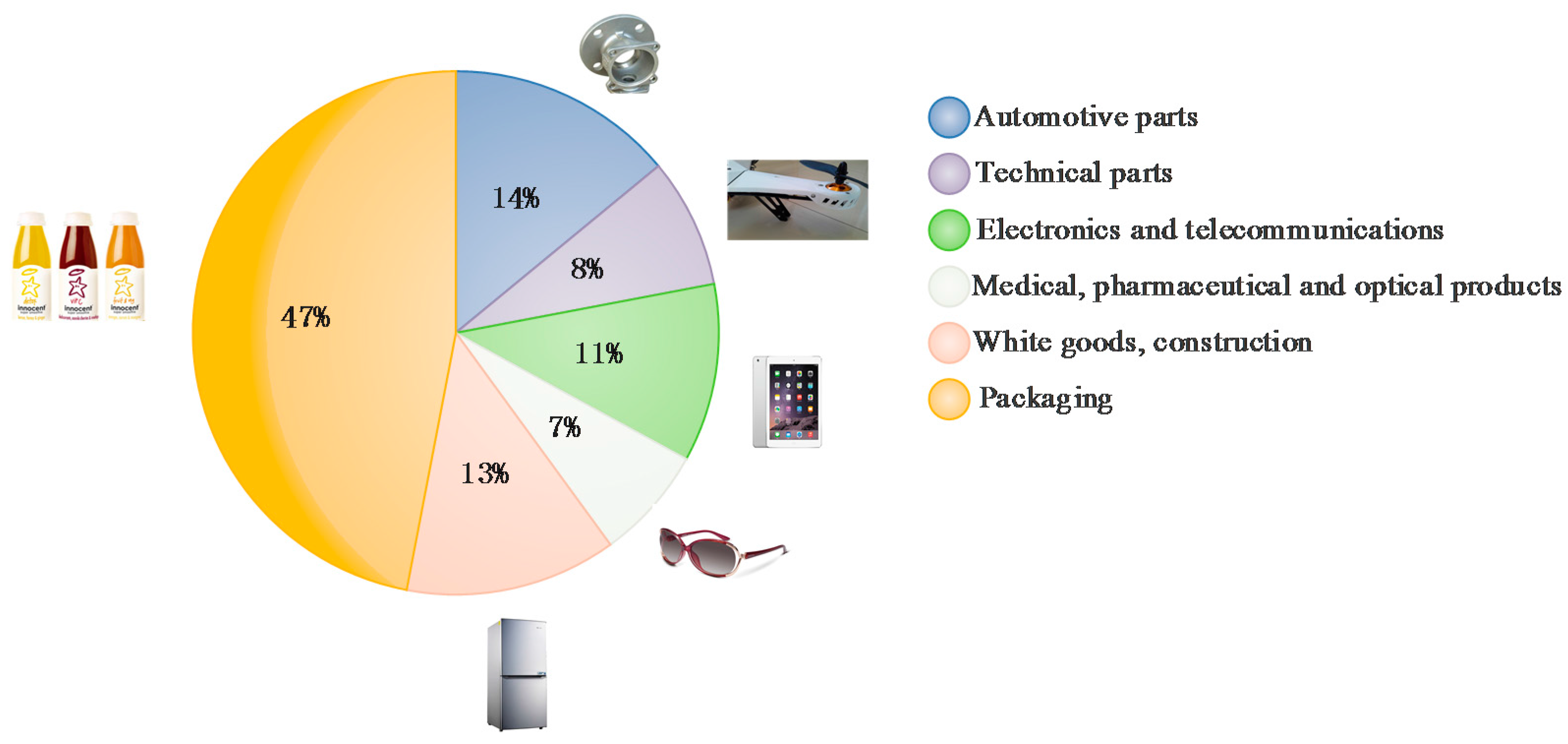
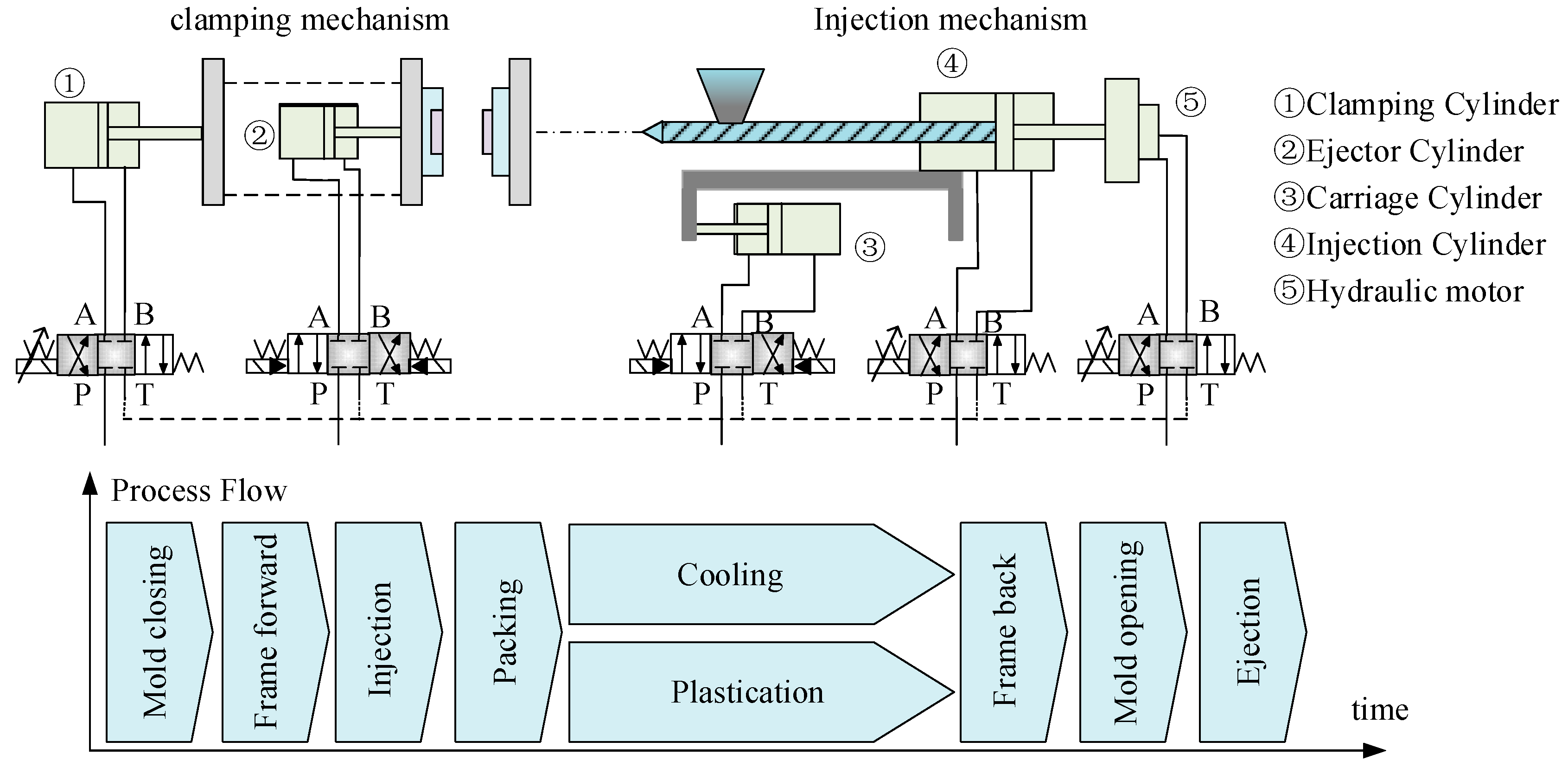
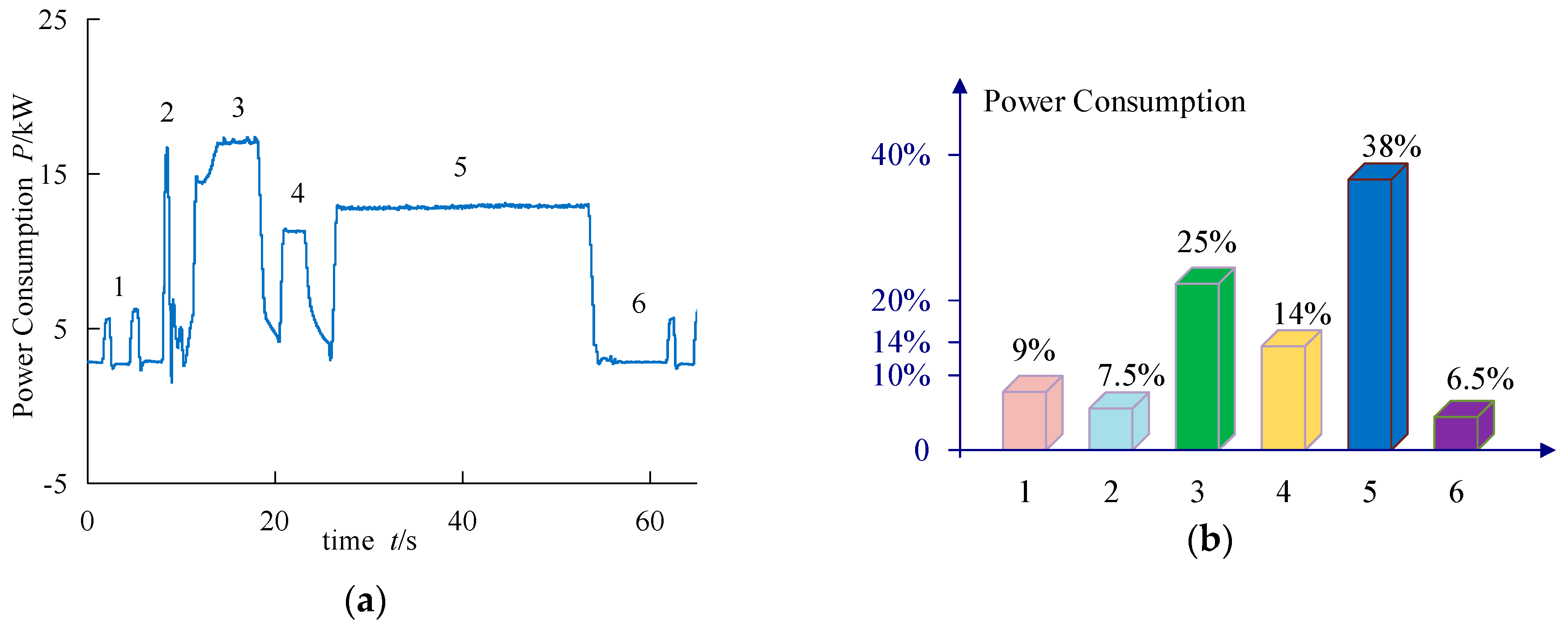
2. Evolvement and Energy Consumption Distribution of Injection-Molding Machines

As a kind of plastic forming equipment, an electric-hydraulic IMM consists of an injection unit, a clamping unit, a hydraulic control unit, a heating unit, a cooling unit, an electrical control unit, a feeding device, and the body [22]. It has several main functions that contain plastification, barrel heating, platen movement, injection, clamping, packing & holding, ejection, and barrel retraction [23]. The operation program may not be exactly the same for different plastic IMMs, but this action can be substantially attributed to a basic program. Figure 2 shows the composition, appearance, and process of a hydraulic IMM.
During the process of injecting and forming, plastic materials are first added to the barrel, and they are then heated by the heating element and begin to melt. With the rotation of the screw, the plastic materials are conveyed forward and pushed onto the head of the screw under pressure. The pre-plastic is completed along with the formation of screw retreating and back pressure forming. Then, the clamping mold mechanism is driven and closed under the control of the clamping cylinder. At the same time, the screw is driven to rotate under the pushing of the injection cylinder, so the molten materials in the chamber are injected into the mold cavity. Then the molten materials are solidified and shaped after packing and cooling. At last, the mold is opened by a clamping mechanism, and the shaped products are ejected under the driving of the ejector. A production cycle is thus completed.
The energy consumption is distributed in all aspects [24,25]. Energy consumption of each part is different for each IMM and depends on part weight, cycle time, machine size, machine type, and machine efficiency. According to the system shown in Figure 2, the power source uses the asynchronous motor (ASM) to drive the fixed displacement pump, and our research group carried out this experimental study. A Model WK400 injection-molding machine was selected to produce a kind of mine cable hook products. Power consumption of the IMM was tested during one duty cycle [26]. The working cycle of an IMM consists of six stages. They are, respectively, clamp closing, injection table moving forward, injection, pack and hold, plastification and cooling, and clamp opening. The distribution of power consumption of a hydraulic IMM in a work cycle is shown in Figure 3 [26]. Figure 3a shows the power curve, and Figure 3b shows the distribution of power consumption. In Figure 3, 1 represents clamp closing, 2 represents frame forward, 3 represents injection, 4 represents packing and holding, 5 represents plastification and cooling, 6 represents clamp opening.
With the data analysis from Figure 3, during the working process of an IMM, the energy consumption ratio of clamp opening, clamp closing, and cooling is very small. However, the energy consumption mainly focuses on the processes of injection, plastification, and cooling for the hydraulic IMM in a work cycle. Especially, in plastification and cooling links, the required load power is relatively small, while the system provides a relatively large amount of power. Therefore, plastification and cooling provide the greatest opportunities for saving energy.

3. Drive Technology of Hydraulic IMM

Developing a highly efficient hydraulic IMM is an urgent task, so all aspects of energy conservation research, such as using “green” polymers, reducing energy usage, and lowering clamp forces and injection pressure, are carried out.
In the auxiliary equipment, replacing conventional heater bands with radiant IR heaters, infrared elements from Rex Materials Inc. (Fowlerville, MI, USA) can be used to convert all heating zones. Haitian Plastics Machinery Group Co. Ltd. (Ningbo, China) has offered Smart Heat barrels as an option on all its IMMs, both all-electric and electric-hydraulic hybrids [27]. In addition, Franklin L. Quilumba, Lyndon K. Lee, Wei-Jen Lee, and Alan Harding used alternative synthetic hydraulic fluid to take the place of conventional fluid in the work process of IMM, which had a significant effect on reducing energy consumption by 16.7% in one test period [16].

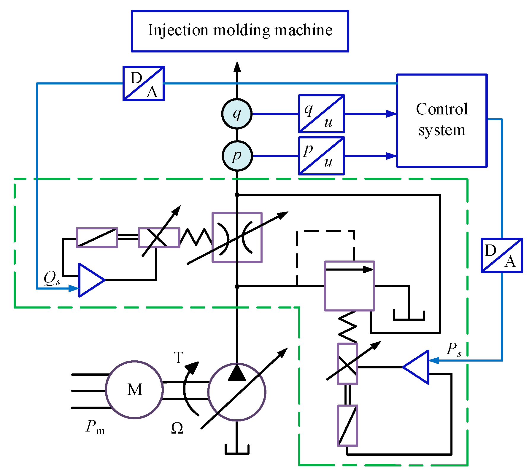
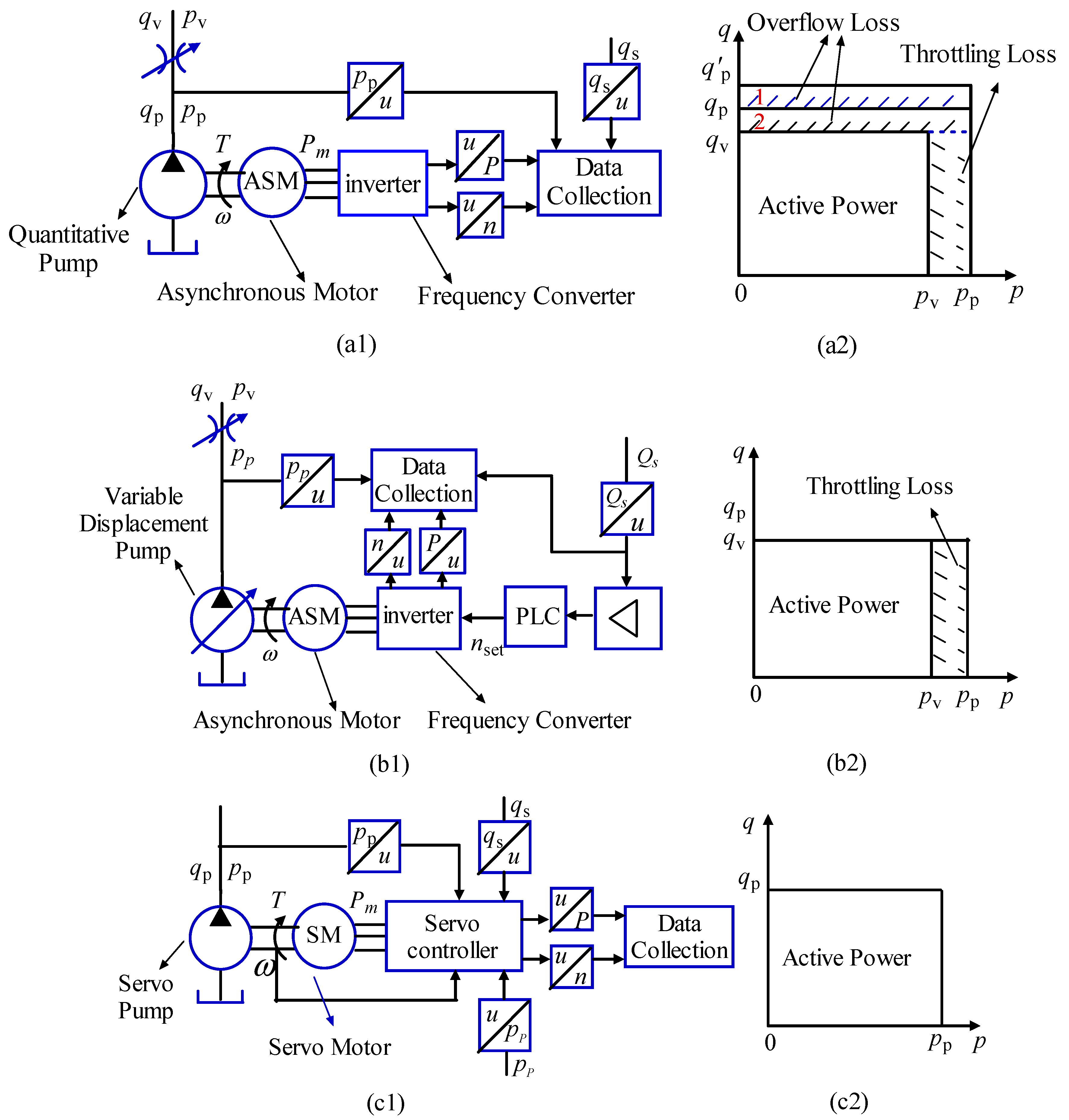
3.1. Energy Conservation Research on Hydraulic Circuits

In hydraulic driving source, conventional hydraulic IMM consists of a fixed pump and a pressure and flow (P/Q) proportional valve, where the pressure and flow are adjusted by P/Q proportional valve. If an asynchronous motor driven by a constant pump is used, the flow is only adjusted by a proportional throttle valve according to system requirements. Extra oil flows back into the tank through the bypass of the proportional overflow valve [28,29]. The structure diagram of a fixed displacement pump drive system is shown in Figure 4.
This control method meets the control of clamping speed, injection speed, packing pressure, screw speed, and top output movement requirements of IMMs [28]. At the same time, it improves the control precision and stability of an IMM. However, it also leads to energy losses associated with flow through one fixed pump and one proportional valve. Especially in the packing process of IMM, this kind of loss is the largest.
In the 1980s, an electro-hydraulic load-sensing control technology was developed by combining a variable pump with an electro-hydraulic proportional valve. The schematic diagram of a load-sensing control system is shown in Figure 5. Velocity adjustment of the actuator is achieved by adjusting the proportional throttle valve and variable pump flow simultaneously. The control method can make pump output flow match the load flow by adopting differential pressure signals of import and export oil through the proportional throttle valve, thereby reducing energy losses [30]. A closed loop control system was designed that combined a load sensitive pump with a servo valve. A practical test proved that energy saving and performance had been achieved [31].
By adopting the load-sensing control, all the flow-related energy loss was eliminated. However, there was still a large throttle loss, especially in the high-speed stage, because of a fixed working pressure in the proportional throttle valve. To eliminate the energy loss of this part, the high response variable pump was driven by a direct closed-loop control of pressure and flow. Therefore, the electro-hydraulic system controlled by a P/Q compound proportional pump was proposed [32]. The control diagram is shown in Figure 6.
The latest development trend of IMMs is the integration of electrical and hydraulic technology, which uses variable frequency drives to control motor speed, so the motor turns at a precisely specified speed to pump the correct oil pressure in this process. The IMM system driven by a variable frequency motor will be 50% more energy-efficient than conventional hydraulics and 20–30% more energy-efficient than modern servo-hydraulics [33]. Therefore, the novel electro-hydraulic technology provides a new way for energy-saving control in IMMs [34]. The German Demag company developed and produced a new kind of electro-hydraulic machine, which is driven by three servo motors and a proportional pump. This scheme is called the hybrid control, whose diagram is shown in Figure 7. In this scheme, a plastification cylinder is directly driven by servo motor, and injection cylinder and clamping cylinder are driven by constant displacement pump controlled servo motor. However, other cylinders are driven by a proportional pump. This plan can greatly reduce the energy consumption of this IMM system [26].

3.2. Energy Conservation Research on Electrical Circuits

With the development of power electronic technology, control technology, and microelectronics technology, variable frequency technology of alternating current (AC) motor has been rapidly developed and applied. If variable frequency technology is applied to a hydraulic system, the velocity of a hydraulic pump can be adjusted by changing the motor speed, and the flow of hydraulic pump can be regulated. In view of the hydraulic circuit shown in Figure 4, variable frequency drive control is adopted for the induction motor. The variable frequency drive control system consists of a variable frequency controller, an asynchronous motor, and a fixed displacement pump.
Assuming that the input power of an asynchronous motor is P1, the output power is Pm, the iron loss is PFe, the copper loss power is PCu, and the stray loss is Pa, the efficiency ηam is expressed as
η am = P m P 1 = P 1 P Fe P Cu P a P 1
Asynchronous motor speed n is expressed as
n = 60 f n p ( 1 s )
where f is the power frequency, np is the number of pole-pairs of motor, and s is the slip ratio of the motor. Then, the output power of asynchronous motor Pm is expressed as
P m = 9.55 M × n = 9.55 × 60 × M × f n p ( 1 s )
where M is the torque of the asynchronous motor.
Assuming that the flow of hydraulic pump is qp, the pressure is pp, the volume loss power is PV, and the torque loss power is PM, the output power Pp is expressed as
P p = P m P V P M = p p × q p
The flow of hydraulic pump qp is deduced as
q p = V × n = 60 × f × V n p ( 1 s )
where V is the displacement of the hydraulic pump. From Equation (5), we learn that the flow of the pump could be changed by adjusting the AC power frequency [35]. Therefore, the output power of hydraulic pump Pp is also converted as
P p = p p × ( V × n ) = p p × 60 × f × V n p ( 1 s )
From the analysis of the hydraulic circuit in Figure 4 in Section 3.1, there are two parts of losses: overflow loss and throttle loss. The overflow loss power PO is expressed as
P O = p p × ( q p q v )
The throttle loss power PT is expressed as
P T = ( p p p v ) × q v
where qv is the the flow of the valve, and pv is the pressure of the valve.
Assuming that the loss of the hydraulic cylinder itself is ignored, the output power of hydraulic system Ps is equal to the load power PL, and Ps can be expressed as
P s = P L = P p P O P T
According to Equations (1), (4), and (9), the output power of the hydraulic system Ps can be deduced as
P s = P 1 P Fe P Cu P a P V P M P O P T
According to Equations (6) and (9), the output power of the hydraulic system Ps can also be deduced as
P s = p p × 60 × f × V n p ( 1 s ) P O P T
The efficiency of the whole system ηs is calculated as
η s = η am × η p × η c = P 1 P Fe P Cu P a P 1 × P m P V P M P m × P p P O P T P p
where ηp is the efficiency of the hydraulic pump, and ηc is the efficiency of the hydraulic system.
In the practical application system, load is constantly changing. Similarly, the required power PL of the load is varied for the IMM system. Especially in the stages of holding pressure and cooling, the required load power PL becomes smaller.
When the load power PL is reduced, if the output power of the motor has been exported the rated power, the output power of the hydraulic pump will remain unchanged. In order to maintain the output power Ps and the load power PL of the hydraulic system equal, according to Equation (9), we can see that the overflow loss power PO and throttle loss power PT will increase. Therefore, it will result in a greater energy waste and a lower efficiency.
When the load power PL is reduced, if variable frequency technology is adopted in the asynchronous motor, the frequency is lowered by adjusting inverter. The speeds of the motor and the hydraulic pump drop, and the output power of hydraulic pump Pp, also decreases. Therefore, the output power of the hydraulic system decreases as the load power decreases. The input power automatically adapts to load power, so the power consumption of this system will be greatly reduced.
Thereby, when input power automatically tracks load power, the output flow and pressure can achieve a good match to system requirements, so this variable frequency technology can greatly reduce power consumption and improve system efficiency.
When frequency control is adopted, motor soft start can be achieved so as to reduce motor wear and increase motor operational life span. Besides, the power factor correction is designed, so as to increase the active power of the electric network and save power consumption. According to the products of injection, the inverter energy saving can be up to 20–70% [36].
If the variable speed control technology is applied in an electro-hydraulic IMM, it can effectively reduce its energy consumption, improve process control, and reduce wear and tear on the motor [37,38,39,40]. In recent years, some research institutions and scholars have developed variable speed technology for energy-saving and have made a series of achievements.
In the 1990s, Helduser put forward a variable speed control for a direct pump control cylinder circuit, reducing the power loss, especially with respect to partial loads or no load. A speed adjustable AC servo motor and a fixed displacement pump were combined to make the electric hydrostatic drive system easy to control, and to improve the dynamic performance of the system. Then, some comparative studies of energy efficiency were conducted in variable displacement control and variable speed control. Variable speed control could obviously achieve less energy consumption and efficiency as high as 98.4%. By developing and testing the application, the results showed that, in a working cycle, the total efficiency of an IMM driven by frequency conversion can reach up to 52%, while the total efficiency of an IMM driven by ordinary hydraulic pressure is less than 25% [41,42,43].
In 1999, Helduser pioneered a variable speed control in an electro-hydraulic IMM, which is used to optimize the efficiency of packing and cooling processes, saving energy [44]. From 1999 to 2011, Professor Long proposed variable speed driven differential cylinder control circuits, which are used for energy-saving control of electro-hydraulic IMMs [45,46]. The principle to control differential cylinders with two speed variable pumps is shown in Figure 8.
In 2008, Takayuki Imamura focused on the efficiency and power consumption of IMM servo driven by a variable speed pump control system, which was compared with the traditional asynchronous motor-driven variable displacement pump system [47]. However, because of the slow dynamic response of asynchronous motors, such motors are substituted for servo motors in order to improve the dynamic response, control accuracy, and low-speed performance of the system. Therefore, the variable frequency drive is vigorously promoted and applied in IMMs [45]. The new electro-hydraulic control technology has opened up new avenues for efficient and energy-saving IMM control.
In 2009, Mao-Hsiung Chiang adopted permanent magnet synchronous motor speed control to replace the traditional throttling and volume control, which reduced the power consumption of IMMs [48]. In 2011, Guan Cheng’s group and Ying Ji’s group separately designed an IMM control system where the servo motor was adopted to drive a fixed displacement pump [49,50]. In 2011, Professor Peng adopted a servo motor driving a fixed displacement pump system to achieve energy-saving control [51]. In 2013, the energy conversion efficiency of the variable speed driving IMM system was analyzed and studied by American scholar F. L. Quilumba [16].
In 2011, our research group conducted some research for five control schemes, which are respectively listed here [52]. Scheme 1 is an asynchronous motor driving a fixed displacement pump. Scheme 2 is a variable speed asynchronous motor driving a fixed displacement pump. Scheme 3 is an asynchronous motor driving a variable displacement pump. Scheme 4 is a variable speed asynchronous motor driving a variable displacement pump. Scheme 1 is an AC servo motor driving a servo pump. The control principle diagram and energy consumption analysis are shown in Figure 9. Figure 9(a1) shows the control system of the fixed displacement pump driven by a variable speed asynchronous motor (ASM). Figure 9(a2) shows the energy consumption distribution where there is overflow loss and throttling loss. When the motor is not adjusted by the variable frequency control, the system overflow loss is relatively large (That is the sum of the shaded Area 1 and 2). When the motor is adjusted by variable frequency control, the overflow loss reduces to Area 2. Figure 9(b1) shows the control system of a variable displacement pump driven by a variable speed asynchronous motor. Figure 9(b2) shows that there is throttling loss. Figure 9(c1) shows the control system of a servo pump driven by a servo motor (SM). Figure 9(c2) shows the energy consumption distribution, and there is no overflow and throttling losses. Aiming to the above five schemes, the same IMM was adopted, and same product produced. Experimental tests were respectively carried out. Table 1 shows the power consumptions of IMM for the five control schemes in a work cycle time.
By comparing Scheme 1 with Scheme 2, we can clearly see that power consumption of Scheme 2 reduces 26.8 kW in a work cycle time. By comparing Scheme 3 with Scheme 4, the power consumption of Scheme 3 reduces 7.5 kW in a work cycle time. According to the above analysis and data comparison, it can be very clearly obtained that variable frequency control can reduce energy consumption. However, in Scheme 5, after an AC servo motor displaces an asynchronous motor, power consumption becomes the smallest. Because the efficiency of an AC servo motor is higher than the efficiency of an asynchronous motor. Then, according to Equation (12), the conclusion is drawn that the energy efficiency of the servo pump system driven by the AC servo motor is the highest.

4. Control Technology of IMMs

4.1. Energy Conservation Control Strategy

By improving system components, i.e., hydraulic and electrical circuits, energy-saving was achieved. However, in order to further reduce loss and improve system performance, certain control strategies have been studied.
In 2004, a study was carried out to simultaneously achieve good velocity control capability and high energy efficiency. The acceptable system consists of velocity control in a hydraulic valve-controlled cylinder system and energy-saving control with both a variable displacement pump system and a variable rotational speed pump system. The feasibility of the integrated control system was thus shown [18]. In 2005, a decoupling fuzzy sliding-mode control strategy was proposed for the integrated control of clamping force and energy-saving for simultaneously improving the accuracy of force control response and energy efficiency in a hydraulic IMM [53]. In 2007, a low-cost and fully digital velocity/pressure controller integrated digital signal processor (DSP) and analog-to-digital converter (ADC) was designed, which demonstrated fast response and precise tracking. An in-parallel interlaced sample-and-hold structure was used in this system to enhance the ability to resist noise and enlarge the sampling frequency of the ADC [54].
In 2009, Mao-Hsiung Chiang investigated a variable rotational speed electro-hydraulic pump-controlled system to improve the response and energy efficiency of hydraulic IMMs. In order to achieve better response and efficiency, he used a constant displacement axial piston pump. In addition, a control strategy of a signed-distance fuzzy sliding mode control was used. Better response and higher energy efficiency of the system were demonstrated in the experiments [48]. In the same year, Shuo Wang developed a new fuzzy controller for the servo motor driving fixed displacement pump system. The research showed that the system was more robust than that of the traditional proportional-integral-derivative (PID) controller and that the speed tracking error decreased to the required injection accuracy. This fuzzy controller is now applied to the Haitian servo IMM [19]. At the same time, a non-dominated sorting genetic algorithm II was adopted by Zhe Wei, and this algorithm had better convergence near the actual Pareto-optimal front. The control strategy solved the design problem of multi-objective performance optimization, and energy-saving was thus achieved in a large IMM [55].
In 2010, Lin and Lian developed a controller, called a hybrid self-organizing fuzzy and radial basis-function neural-network controller, that can adjust the appropriate parameter values of a self-organizing fuzzy controller in a timely manner by selecting and changing both the learning rate and the weighting distribution of the controller. This controller was successful at reducing speed errors, maintaining the stability of the system, increasing the injection rate, and improving the quality of plastic products [56]. In the same year, an energy control strategy based on logic gate was designed by Tao Liu for a parallel hydraulic hybrid vehicle and was used to realize the switching between different working modes, whose control goal was to achieve parameter optimization based on the principle of optimal energy-saving and improved the performance of the whole machine [57].
In 2011, Wang designed a gray fuzzy proportional-integral (PI) controller, which integrated a predictive gray system, a robust fuzzy ratiocination, and a traditional PI control algorithm. This controller achieved a more desirable performance and energy-saving control in an IMM driven by a servo motor [58]. In 2012, the adaptive fuzzy PID compound control was put forward by Gang Feng for variable speed motor-driven pump control system, which achieved energy-saving and strong robustness of the system [59]. In the same year, Ning-Yun Lu adopted the genetic algorithm-based lexicographic method for realizing energy saving and ensuring product quality at the same time. Thus, energy utilization increased by about 10% [60].
In 2014, Fenfen Qi adopted a nonlinear fuzzy control strategy for a servo motor driving IMM system. The experiment verified the improvement in response speed, injection accuracy, and energy efficiency [61]. In the same year, Bing Xu designed a PID controller with a model-based feed forward compensator and used a parameter selection method simultaneously for achieving desired force control accuracy and low energy consumption. As a result, the energy consumption of this system, compared with that of the traditional system, was reduced by 71%, and the robustness of the system was greatly enhanced [62]. Yong-Gang Peng put forward a nonlinear model predictive control based on the neuro dynamic optimization method instead of a traditional PID method, which was applied in an injection molding process for a servo motor driving constant pump hydraulic system. The results showed that online optimization, quick response, favorable controlling precision, and smaller overshoot were achieved [63]. According to the topology optimization based on the method of finite element analysis, Bin Ren proposed other optimization design scheme for stationary platen and chose a preferred alternative that can realize low energy consumption and high injection precision [20].
The thermal control of an injection molding system is a key issue in the development of high-efficiency injection molds. In 2015, Byeong-Ho Jeong, Nam-Hoon Kim, and Kang-Yeon Lee proposed a DSP-based PID control system for thermal control, which achieved high precision, better performance, and good stability at a low cost [21].

4.2. Energy Monitoring System

In addition, Bosch Rexroth developed a software and a control package to monitor and optimize energy utilization throughout the molding process (Bosch Rexroth AG in Lohr am Main, Germany) [64]. The ABB Group introduced energy monitoring capabilities in driving motors [64]. Krauss Maffei also developed motion control software, which automatically optimized screw speed and other settings for energy efficiency. In addition, Engel discussed new “ecobalance” software to reduce peak energy consumption automatically [10].
In addition, energy monitoring can monitor various parameters, operating the state and performance of IMM. It can also provide references for energy-saving methods. Therefore, some researchers and companies began to study it. Star Master International Limited developed an energy monitoring system that could monitor the operating capacity of the oil pump motor by detecting the pressure and volume of IMM [65].
In 2010, A. Weissman and A. Ananthanarayanan et al. made a first attempt, according to the computer-aided design (CAD) model of the parts, the material name, and the production volume, as well as the use of simulation software, to obtain an accurate estimate of the total energy consumption [66].
In 2011, a finite-state machine was used to model energy consumption patterns of engineering processes, and a two-stage framework combining a Savizky–Golay filter with neural network was proposed to classify energy patterns. This method achieved an accuracy of 95.85% in identification of machine operation states and further realized the prediction of machine operation states and energy consumption patterns [67]. In the same year, based on non-intrusive load monitoring, a discrete wavelet transform and a modified universal threshold filter were used to divide time-series data into segments by detecting stepwise changes. A two-stage fuzzy c-means was then used to cluster extracted segments into groups according to existing operation states [68]. This year Hanieh Mianehrow and Ali Abbasian analyzed the factors that affected energy consumption through energy monitoring, and its aim was to provide methods for improving energy efficiency [69].

5. Energy Regeneration

5.1. Recovery and Reuse of Hydraulic Braking Energy

IMMs have multiple operating units and intermittent operation. During operation, these operating units frequently start and stop and frequently accelerate and decelerate, thereby resulting in a certain amount of braking energy. If there are no recovery measures, braking energy is consumed in the form of heat. Moreover, additional cooling links need to be added. Therefore, in recent years, domestic and foreign scholars have been concerned with the recovery and reuse of hydraulic energy and electrical energy.
More energy saving is possible with linear “stop/go” movements such as clamp-open and clamp-close by regenerating electricity from braking instead of dissipating it as heat [70]. In 2004, Peter Jarosch analyzed the accumulator storage control according to a comparative study on the energy consumption of IMMs [71]. In 2006, Professor Quan adopted a variable speed pump, accumulator, and proportional valve to control differential cylinders for the clamping mechanism of IMMs. Hydraulic accumulator will recover energy when cylinder returns, while it will release energy when cylinder protrudes. Therefore, energy consumption is reduced, and the utilization rate of energy improves [72]. In the same year, Robin Kent used energy storage technology to reduce the installed power and energy consumption of an IMM system [73].
In 2008 and 2010, a control idea of electro-hydraulic variable speed based on energy regulation was proposed. The energy regulator consisted of an accumulator, a proportional throttle valve, and a relief valve, which was to reduce the pressure shock during the returning and protruding of the cylinder. The experiment verified an energy-saving effect [74,75].
In 2010, Yang reformed traditional P/Q valve-controlled hydraulic IMM circuits and developed an energy saving module with a hydraulic accumulator for reducing energy consumption [76]. In 2013, Ningbo Haitian Plastic Machinery Co. Ltd., which was the leading enterprise in the production of plastic IMMs in China, used an accumulator to store oil during the cooling stage and to provide oil during the injection process, so the energy utilization rate was improved [77].

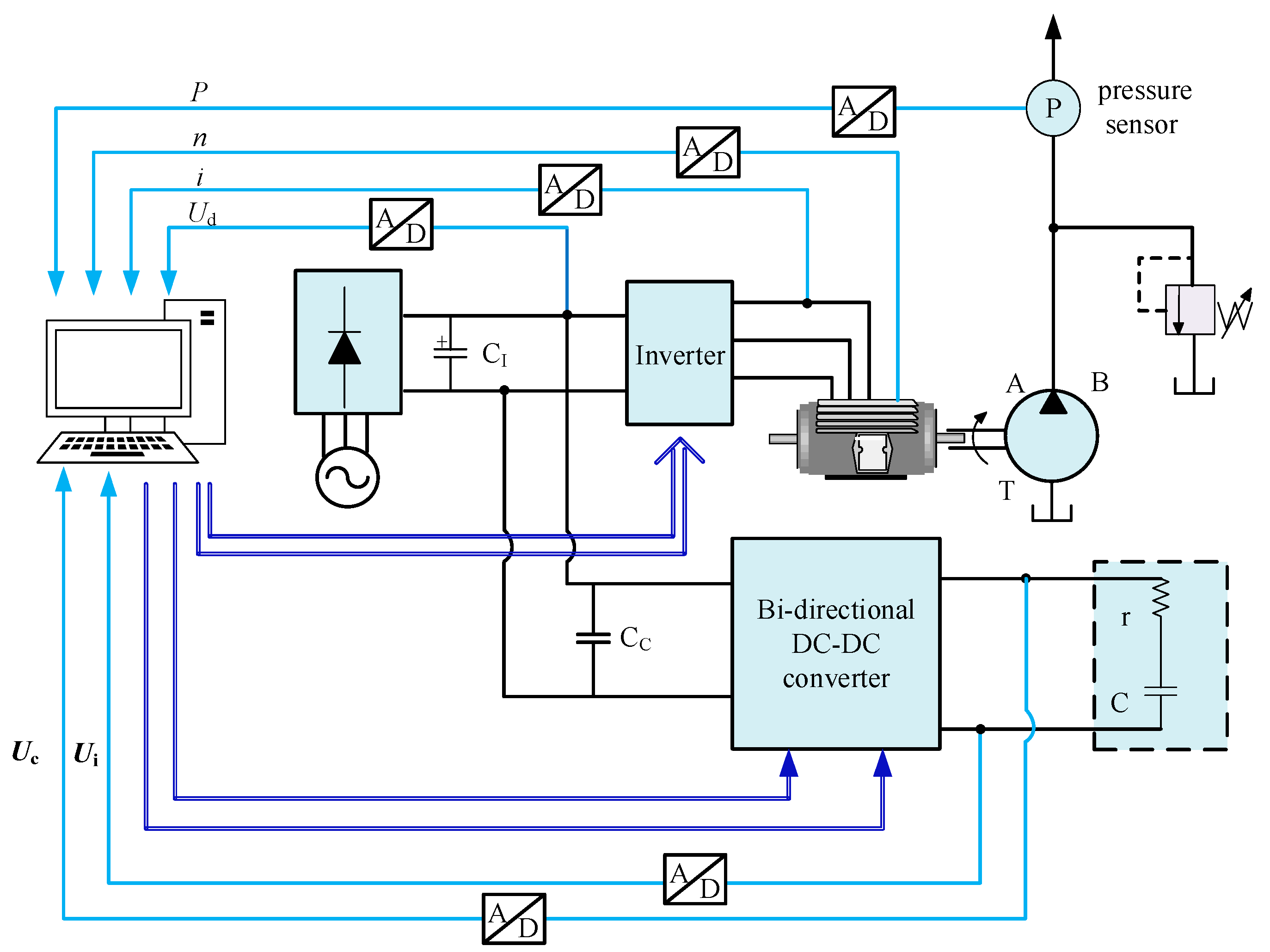
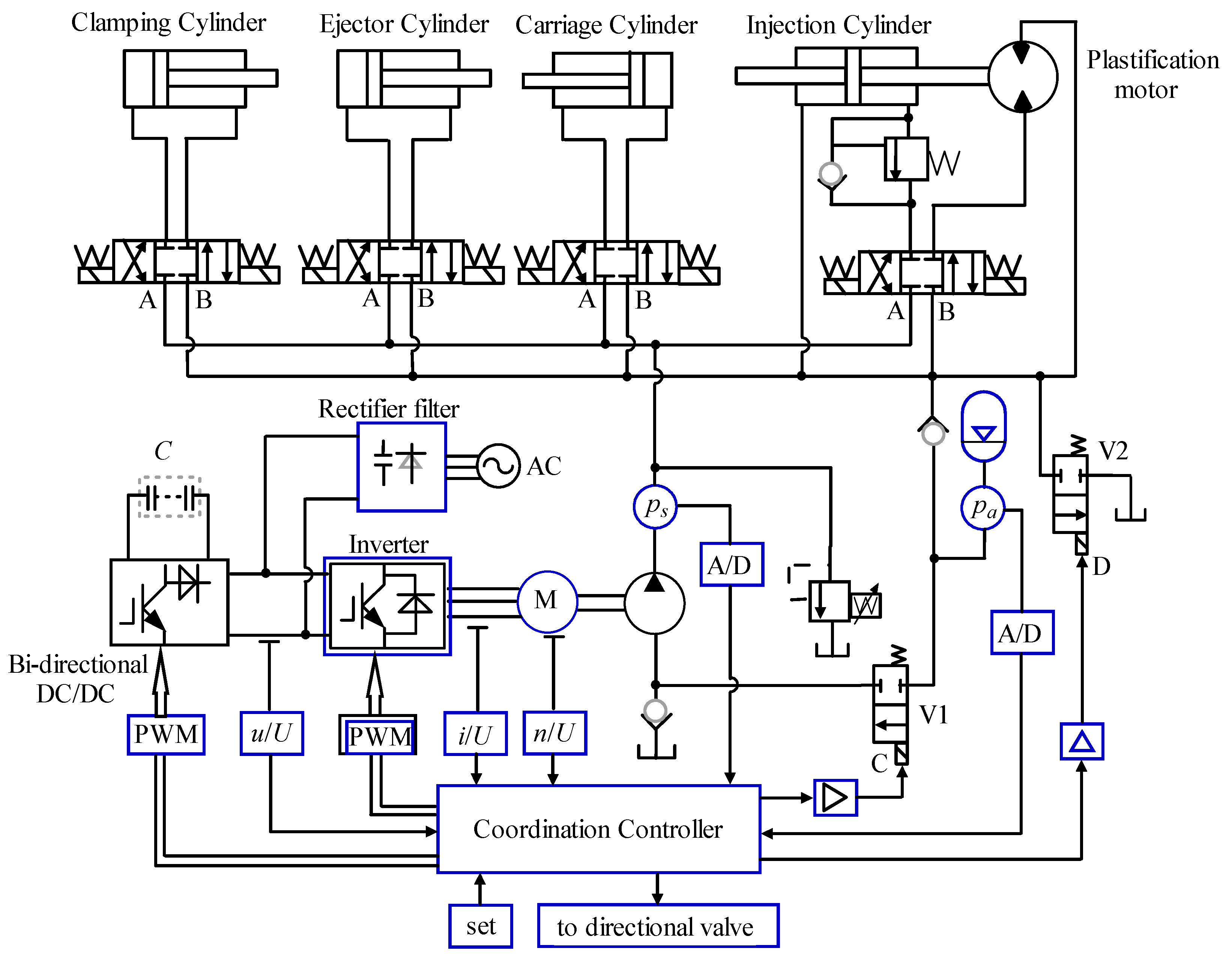
5.2. Recovery and Reuse of Electric Braking Energy

Research on recovery and reuse of electric braking energy is widely applied in many different fields, so it is also a research hotspot on the energy-saving control of IMMs. Electrical braking energy is fed to the power grid, which is an effective solution for energy recovery and utilization. However, this mode will cause power grid voltage fluctuations and increase harmonic content such that the quality of the power grid will decrease [14,78]. Therefore, exploring a “green” recovery device of braking energy has been the goal of the majority of researchers. Super capacitor energy storage is a common mode of electrical energy storage. The super capacitor has high power, a strong output capacity, excellent charge–discharge performance, fast response, and a long service life, so it is widely used as an energy storage device.
In 2002, Duran-Gomez employed a flyback bi-directional direct current to direct current (DC/DC) converter circuit with a high voltage/power transmission ratio to perform the closed-loop control of direct current (DC) bus voltage. Therefore, it can achieve energy storage and the release of the super capacitor [13]. In 2006, the Ansaldobreda Research Department has carried out a study and experimentation on an innovative energy storage system of an electrical vehicle. It consists of super capacitor modules and achieves energy optimization and high energy recovery during the braking phase [79]. In 2008, Cheng studied the energy recovery and utilization of a super capacitor for special saloon carriage [80]. In the same year, Professor Cao studied the influence of the super capacitor and battery hybrid power supply and analyzed the recovery and utilization of braking energy for electric vehicle [81]. In 2009, Brabetz applied the super capacitor for electric vehicles to improve the energy efficiency of the system [82]. In the same year, Rao introduced a super capacitor to the high voltage and large capacity variable frequency controller for achieving motor brake energy storage and reuse, while improving system performance [83]. In 2010, Mishima Tomokazu used an energy storage device that combined a push–pull bi-directional DC/DC converter with a super capacitor for achieving bi-directional control of energy and reducing transmission loss [84]. Takahashi provided a novel control scheme of an energy recovery system with an electric double-layer capacitor and a bi-directional DC/DC converter. An experiment verified a 49% energy-saving effect for the control system [85]. The system structure diagram of energy recovery and reuse is shown in Figure 10. In the same year, Xu used a number of super capacitor modules in a series to adapt to different power supply system for traction power grid applications [86]. Liu applied a super capacitor in an excavator for achieving potential energy regeneration and utilization [87].
In 2013, Dipankar De focused on the design of the DC/DC power converter for achieving energy recovery and utilization control of the super capacitor [88]. In the same year, Z. Deng applied a super capacitor to an elevator for the recovery of brake energy and analyzed the lower influence of power fluctuation on the power grid quality [89].
In 2014, the control system of a peak power shaving that consisted of a multiphase bidirectional DC/DC converter and super capacitors was designed. When the injection motor was at rest, energy passed through the multiphase bidirectional DC/DC converter and was stored in the super capacitors. When the injection motor accelerated, energy was released. Consequently, the peak power was shaved by 70%, and significant energy conservation was thus shown [15].
In 2015, a hybrid energy storage system based on a multiport DC/DC converter, aimed at a DC micro grid system, was proposed. The hybrid energy storage system, composed of a super capacitor and a storage battery, combined the advantages of the two and made up for the shortcomings of the weak energy storage capacity of the super capacitor. Therefore, the service life of the storage device was prolonged. Simultaneously, in order to keep the super capacitor voltage close to the rated value and ensure the battery energy distribution balance, an adaptive energy control strategy based on the moving average filtering algorithm was put forward [90]. In 2016, Wei and his group studied the super capacitor storage energy system and proposed a control strategy based on a modular multilevel converter that achieved voltage balance control of energy storage components and double loop control of the DC bus side current [91].

6. Challenges and Prospects

This paper mainly reviews hydraulic drive circuits, electric drive circuits, control strategies, the regeneration of hydraulic braking, and electric braking energy for hydraulic IMMs. Although the energy-saving technology of IMMs has made some effective achievements and developments, the energy recovery technology of hydraulic IMMs still faces several challenges. From the above study, energy regeneration is independently carried out, respectively, on a hydraulic link and an electrical link, so it can only achieve energy saving for a single link. Therefore, if the braking energy from the hydraulic and the electrical link simultaneously is recycled and used, it will be one of the effective ways for the improvement of energy efficiency. However, the two links carry out energy recovery at the same time under independent control, which will lead to system vibration or movement disorders, and even cause the equipment to not work properly. Therefore, the coordination control of the hydraulic and electrical links is the next problem to solve.
For this problem, our research group puts forward a coordinated control strategy of an electro-hydraulic mixed energy recovery for hydraulic IMMs. The principle of the coordination control strategy is shown in Figure 11. During the operation of the hydraulic IMMs, the system pressure, the accumulator port pressure, the motor speed, the motor current, and the DC bus voltage are collected in real time and transmitted to the coordination controller. According to the actual signal and the given signal, and combining with load conditions, the coordination controller will output a control signal to drive the various hydraulic cylinders. Assuming that the clamping cylinder is driven and extended, the fluid in the rod cavity of cylinder flows into the accumulator through the check valve. Then, the accumulator will absorb the braking energy and shock caused by the sudden stop of the clamping cylinder and the contact between the front and rear molds. At the same time, by the real-time acquisition of the AC motor current direction and the DC bus voltage, the coordination controller comprehensively judges the operating status of AC motor. In addition, the coordination controller is to control the bidirectional DC/DC converter, thereby realizing the automatic energy storage and release of the supercapacitor. When the mold clamping is completed, the coordination controller controls the carriage cylinder to move forward. The coordination controller then controls whether Switch Valve V1 or Switch Valve V2 is connected according to the system pressure and the accumulator port pressure. If the accumulator port pressure is larger, and the difference between the system pressure and the accumulator port pressure is too small, the coordination controller drives Switch Valve V1. Then, the accumulator supplies oil to the hydraulic pump, and the coordination controller controls the switch valve to connect the low pressure port B of the directional valve to the oil tank. At the same time, the controller adjusts the motor speed and the output power according to the system pressure, the motor speed, and the load changes. Therefore, the output power will match the required power of the load in real time, thereby to achieve minimum output power.
In accordance with the above control law, the electro-hydraulic IMM in turn completes injection → pack and hold → plastification and cooling → clamp opening → clamp closing → frame forward periodic work. Therefore, the coordination control of an electro-hydraulic mixed energy recovery for hydraulic IMMs is achieved.
If the coordination control is applied in electric-hydraulic injection-molding equipment, the system efficiency can be further improved. However, the application of servo motor drive sytem is narrowed, because the servo motor power is limited. In practice, the application of some high-power electric-hydraulic injection-molding equipment is more extensive, and there are more conditions of partial loads or no load. Therefore, there is a large energy-saving space. The above energy conservation control technology will be able to greatly reduce their energy consumption if it is used for the high-power electric-hydraulic injection-molding equipment system. And then the speed control of the high-voltage high-power motor is required. However, the emergence and development of high-voltage frequency conversion technology make the settlement of this problem possible. The next step, if the hydraulic pump control system is combined with high-voltage frequency conversion technology, can not only increase the system drive power but also reduce the energy consumption of the high-power electric-hydraulic injection-molding equipment system. This will promote the development of high-power electric-hydraulic injection-molding equipment. In summary, electric-hydraulic injection-molding equipment is moving toward low-loss, high-efficiency, and green energy-saving development and will have a wide range of application prospects.

Acknowledgments

The authors would like to thank the anonymous reviewers for their valuable comments. This research work is supported by the National Nature Science Foundation of China (Grant No. 51405330).

Author Contributions

Hongjuan Zhang and Baoquan Jin conceived and designed the study; Lu Ren and Yan Gao developed the design of the illustration. All authors contributed to the detailed survey of the literature and the state of the art, which were essential for the completion of this review paper.

Conflicts of Interest

The authors declare no conflict of interest.

Abbreviation

IMMinjection-molding machineADCanalog-to-digital converter
P/Qpressure and flowPIDproportional integral derivative
ACalternating currentPIproportional integral
ASMasynchronous motorCADComputer-aided design
PLCprogrammable logic controllerDC/DCdirect current to direct current
DCdirect currentPWMpulse width modulation
SMservo motorA/Danalog to digital
DSPdigital signal processorD/Adigital to analog

References

  1. Erne, B. Injection Molding Machines Benefit from Technology-Neutral Design Approach. Available online: http://www.moog.com/literature/ICD/moogindustrialnewsletterissue34.pdf (accessed on 26 June 2013).
  2. Global and China Injection Molding Machine Industry Report, 2014–2016. Available online: http://www.researchinchina.com/Htmls/Report/2015/9074.html (accessed on 23 December 2016).
  3. Energy Management in Plastics Processing. Available online: http://www.pcn.org/Technical%20Notes%20-%20Energy%20(1%20-%208).pdf (accessed on 22 March 2017).
  4. Understanding Energy Consumption in Injection Moulding Machine. Available online: http://www.pitfallsinmolding.com/energyeffic1.html (accessed on 25 March 2016).
  5. China Plastics Injection Machine Market Panorama Survey and Development Trend Research Report during 2015–2022 Years. Available online: http://www.chyxx.com/research/201508/340721.html (accessed on 25 August 2015).
  6. Energy Utilization in Injection Molding. Available online: http://www.energy.ca.gov/process/pubs/energy_utilizatn_in_inj.pdf (accessed on 25 December 2016).
  7. In the Next Five Years, the Consumption of Injection Molding Machines Is Likely to Exceed 2 Times the Power Generation Capacity of the Three Gorges. Available online: http://www.wanguan.com/news/32112.html (accessed on 17 October 2016).
  8. Godec, D.; Rujnic-Sokele, M.; Šercer, M. Processing parameters influencing energy efficient injection moulding of plastics and rubbers/Utjecaj parametara prerade na energijski u inkovito injekcijsko pre anje plastike i gume. Polimeri 2013, 33, 112–117. [Google Scholar]
  9. Liebig, G. Comparison of the Performance of a Hybrid and an All-electric Machine. Kunststoffe/Plast. Eur. 2002, 7, 16–17. [Google Scholar]
  10. Schut, J.H. Does Low Constant Pressure Injection Molding Work? Available online: https://plasticsengineeringblog.com/2015/09/ (accessed on 31 August 2015).
  11. Akasaka, N. Design Method by use of Control Similarity Principle applied for a Load Simulator of Electric-motor Driven Injection Molding Machine. In Proceedings of the International Conference on Control, Automation and system, Seoul, Korea, 14–17 October 2008; IEEE: Piscataway, NJ, USA, 2008. [Google Scholar] [CrossRef]
  12. Schut, J.H. Eco-Molding: More Power for Less Energy: How Much More Efficient Can Injection Molding Machines Get? Plastics Engineering: Sheboygan, WI, USA, 2015; Available online: http://read.nxtbook.com/wiley/plasticsengineering/march2015/coverstory_ecomolding.html (accessed on 5 April 2016).
  13. Duran-Gomez, J.L.; Enjeti, P.N.; Jouanne, A.V. An approach to achieve ride-through of an adjustable speed drive with flyback converter modules powered by super capacitors. IEEE Trans. Ind. Appl. 2002, 3, 514–522. [Google Scholar] [CrossRef]
  14. Rodriguez, J.R.; Dixon, J.W.; Espinoza, J.R.; Pontt, J.; Lezana, P. PWM regenerative rectifiers: State of the art. IEEE Trans. Ind. Electron. 2005, 52, 5–22. [Google Scholar] [CrossRef]
  15. Akiyoshi, H.; Hiraki, E.; Tanaka, T.; Okamoto, M.; Matsuo, T.; Ochi, K. Peak Power Shaving of an Electric Injection Molding Machine with Supercapacitors. IEEE Trans. Ind. Appl. 2014, 50, 1114–1120. [Google Scholar] [CrossRef]
  16. Quilumba, F.L.; Lee, L.K.; Lee, W.J.; Harding, A. Improving hydraulic system energy efficiency with high performance hydraulic fluids. IEEE Trans. Ind. Appl. 2014, 50, 1313–1321. [Google Scholar] [CrossRef]
  17. Thomas, A.R.; Speight, R.G.; Annareddy, M. Using injection moulding simulation to develop environmentally friendly products. Plast. Rubber Compos. 2013, 37, 184–189. [Google Scholar] [CrossRef]
  18. Chiang, M.H.; Lee, L.W.; Tsai, J.J. The concurrent implementation of high velocity control performance and high energy efficiency for hydraulic injection moulding machines. Int. J. Adv. Manuf. Technol. 2004, 23, 256–262. [Google Scholar] [CrossRef]
  19. Shuo, W.; Ji, Y.; Weian, Z.; Min, K. Fuzzy control of the ram velocity in energy-saving servo injection molding machines. In Proceedings of the International Technology and Innovation Conference, Xi’an, China, 12–14 October 2009; IET: London, UK, 2009. [Google Scholar] [CrossRef]
  20. Ren, B.; Zhang, S.Y.; Tan, J.R. Structural Scheme Optimization Design for the Stationary Platen of a Precision Plastic Injection Molding Machine. Chin. J. Mech. Eng. 2014, 27, 714–721. [Google Scholar] [CrossRef]
  21. Jeong, B.H.; Kim, N.H.; Lee, K.Y. Optimized Digital Proportional Integral Derivative Controller for Heating and Cooling Injection Molding System. J. Electr. Eng. Technol. 2015, 10, 1383–1388. [Google Scholar] [CrossRef]
  22. Socks, M. The Promise of All-Electric Injection Molding Machines: A Promise Kept? ACEEE Summer Study on Energy Efficiency in Industry 2005; Energy Efficiency in Industry: Washington, DC, USA; pp. 155–166. Available online: http://aceee.org/files/proceedings/2005/data/papers/SS05_Panel01_Paper15.pdf (accessed on 5 April 2016).
  23. Li, P. Modern Injection Molding Machine Control, 1st ed.; China Light Industry Press: Beijing, China, 2004; pp. 23–27. ISBN 7501932824. [Google Scholar]
  24. Madan, J.; Mani, M.; Kevin, W.L. Characterizing Energy Consumption of the Injection Molding Process. In Proceedings of the ASME 2013 International Manufacturing Science and Engineering Conference, Madison, WI, USA, 10–14 June 2013. [Google Scholar]
  25. Competition Bubbles Up Again in Physical Foam Molding. Available online: https://plasticsengineeringblog.com/2016/04/14/competition-bubbles-up-again-in-physical-foam-molding/ (accessed on 8 April 2016).
  26. Zhang, H.J. Research on Variable Speed Pump—Controlled Differential Cylinder and Low Energy Consumption Injection Molding Machine. Ph.D. Thesis, Taiyuan University of Technology, Taiyuan, China, 2011. [Google Scholar]
  27. Energy Efficiency in Plastics Processing Practical Worksheets for Industry. Available online: http://www.tangram.co.uk/TI-Energy%20Worksheets%20(Plastics)%20-%20Tangram.PDF (accessed on 20 April 2016).
  28. Liu, H.B.; Zhu, X.H.; Zhu, Z.D.; Sun, H.P. The Energy-saving Application for Injection Molding Machine. Chin. Hydraul. Pneum. 2007, 8, e1001055. [Google Scholar] [CrossRef]
  29. Moog-Plastics-Injection-Molding-Overview-en. Available online: http://www.moog.com/literature/ICD/Moog-Plastics-InjectionMolding-Overview-en.pdf (accessed on 18 April 2017).
  30. Wen, S.P.; Jiang, J.Q. The latest development and application of energy saving control technique for injection molding machine. Eng. Plast. Appl. 2006, 34, 59–62. (In Chinese) [Google Scholar] [CrossRef]
  31. Electrohydraulic Control in Plastic Parts Production. Available online: http://www.hydraulicspneumatics.com/200/TechZone/HydraulicValves/Article/False/45407/TechZone-HydraulicValves (accessed on 25 April 2017).
  32. Quan, L.; Li, F.L. Energy saving principle and latest technology of electro hydraulic control system for injection molding machine. Mach. Tool Hydraul. 1999, 5, 6–7. (In Chinese) [Google Scholar] [CrossRef]
  33. Hong, S.P.; Nguyen, T.T. Optimization of injection molding process for car fender in consideration of energy efficiency and product quality. J. Comput. Des. Eng. 2014, 1, 256–265. [Google Scholar] [CrossRef]
  34. Quan, L. Injection Molding Machine System Drived by Mechatronics and Electro-Hydraulic Compound Control. CN 200610012479.6, 7 March 2006. [Google Scholar]
  35. Concise Technologies. Energy Saving and Other Benefits of AC Drive Systems for Injection Molding. Available online: http://www.conciseusa.com/eng_sav/ (accessed on 20 April 2016).
  36. Frequency Inverters. Inverter in Injection Molding Machine Advantages. Available online: http://www.frequencyinverters.org/inverter-in-injection-molding-machine-advantages-609325.html (accessed on 15 April 2016).
  37. Yu, D.; Lu, G.; Zhou, Y.; Zhang, T.; Yu, D. MATLAB Modeling and Analysis of the Electro-Hydraulic Control System of Injection Molding Machine. Available online: https://link.springer.com/chapter/10.1007/978-3-642-54236-7_69 (accessed on 20 April 2016).
  38. Muharnmad, B.N.; Wang, S.P. Optimization Based on Convergence Velocity and Reliability for Hydraulic Servo System. Chin. J. Aeronaut. 2009, 22, 407–412. [Google Scholar] [CrossRef]
  39. Chol, S.H.; Räcklebe, S.; Helduser, S. Position tracking control of a clamp-cylinder for energy-saving injection moulding machines with electric-hydrostatic drives. Proc. Inst. Mech. Eng. Part I J. Syst. Control Eng. 2009, 223, 479–491. [Google Scholar] [CrossRef]
  40. Smart Watt. 3 Ways to Increase Energy Efficiency in Injection Molding. Available online: http://news.smartwattinc.com/blog/3-ways-to-increase-energy-efficiency-in-injection-molding (accessed on 6 May 2016).
  41. Rahmfeld, R. Development and Control of Energy Saving Hydraulic Servo Drives for Mobile Systems; VDI: Duisburg, Gemany, 2002; pp. 1–127. ISBN 9783183527120. [Google Scholar]
  42. Helduser, S. Moderne hydraulische Antriebe und Steuerungen am Beispiel von Kunststoff -Spritzgieß- maschinen. Ölhydraulik Pneum. 1995, 10, 720–725. [Google Scholar]
  43. Helduser, S. Innovationen im Maschinenbau durch fluidtechnische Komponenten und Systeme. Ölhydraulik Pneum. 1996, 6, 380–395. [Google Scholar]
  44. Helduser, S. Electric-hydrostatic drive—An innovative energy-saving power and motion control system. Proc. Inst. Mech. Eng. Part I J. Syst. Control Eng. 1999, 213, 427–437. [Google Scholar] [CrossRef]
  45. Practical Optimization: A Gentle Introduction. Available online: http://www.sce.carleton.ca/faculty/chinneck/po.html (accessed on 2 March 2016).
  46. Neubert, T.; Helduser, S. Principle to closed loop control differential cylinder with double speed variable pumps and single loop control signal. Chin. J. Mech. Eng. 2004, 17, 85–88. [Google Scholar] [CrossRef]
  47. Imamura, T.; Sawada, Y.; Ichikawa, M.; Nakamura, H. Energy-saving hybrid hydraulic system comprising highly efficient IPM motor and inverter, for injection molding and manufacturing machine. In Proceedings of the JFPS International Symposium on Fluid Power, Toyama, Japan, 15–18 September 2008; pp. 117–120. [Google Scholar] [CrossRef]
  48. Chiang, M.H.; Chen, C.C. The high response and high efficiency velocity control of a hydraulic injection molding machine using a variable rotational speed electro-hydraulic pump-controlled system. Int. J. Adv. Manuf. Technol. 2009, 43, 841–851. [Google Scholar] [CrossRef]
  49. Wang, S.; Ying, J.; Chen, Z.C.; Feng, Y. A new fuzzy self-tuning method for controlling packing pressure of a high-accuracy injection molding machine. Zhejiang Daxue Xuebao Gongxue Ban J. Zhejiang Univ. 2011, 45, 1370–1375. [Google Scholar] [CrossRef]
  50. Cheng, G.; Hua, P. Fuzzy control of injection pressure of injection molding machines based on a nonlinear function. J. Zhejiang Univ. Eng. Sci. 2011, 45, 1382–1386. [Google Scholar] [CrossRef]
  51. Peng, Y. Application and Control Strategy of Servo Motor Driven Constant Pump Hydraulic System in Precision Injection Molding. J. Mech. Eng. 2011, 47, 800–809. [Google Scholar] [CrossRef]
  52. Zhang, H.J.; Quan, L.; Li, B. Comparative Study on Energy Efficiency of the Electro-hydraulic Control System in Injection Molding Machine. J. Mech. Eng. 2012, 48, 180. [Google Scholar] [CrossRef]
  53. Chiang, M.H.; Yeh, Y.P.; Yang, F.L.; Chen, Y.N. Integrated control of clamping force and energy-saving in hydraulic injection moulding machines using decoupling fuzzy sliding-mode control. Int. J. Adv. Manuf. Technol. 2005, 27, 53–62. [Google Scholar] [CrossRef]
  54. Wang, M.S.; Chang, C.M. DSP-Based adaptive fuzzy velocity/pressure control of injection molding machines. J. Chin. Inst. Eng. 2007, 30, 819–827. [Google Scholar] [CrossRef]
  55. Wei, Z.; Feng, Y.X.; Tan, J.R.; Wang, J.L.; Li, Z.K. Multi-objective performance optimal design of large-scale injection molding machine. Int. J. Adv. Manuf. Technol. 2009, 41, 242–249. [Google Scholar] [CrossRef]
  56. Lin, J.; Lian, R.J. Hybrid self-organizing fuzzy and radial basis-function neural-network controller for gas-assisted injection molding combination systems. Mechatronics 2010, 20, 698–711. [Google Scholar] [CrossRef]
  57. Liu, T.; Jiang, J. Energy control strategy research of parallel hydraulic hybrid vehicle. Dongnan Daxue Xuebao 2010, 40, 111–116. [Google Scholar] [CrossRef]
  58. Wang, S.; Ying, J.; Chen, Z.C.; Cai, K. Grey fuzzy PI control for packing pressure during injection molding process. J. Mech. Sci. Technol. 2011, 25, 1061–1068. [Google Scholar] [CrossRef]
  59. Feng, G.; Qi, J.B.; Zhang, C.G.; Zhang, Y. Research on Fuzzy-PID Compound Control in Inverter-Driven Energy-Saving Technology for Injection Molding Machine. Adv. Mater. Res. 2012, 538–541, 1057–1060. [Google Scholar] [CrossRef]
  60. Lu, N.Y.; Gong, G.X.; Yang, Y.; LU, Jian-Hua. Multi-objective process parameter optimization for energy saving in injection molding process. J. Zhejiang Univ. Sci. A 2012, 13, 382–394. [Google Scholar] [CrossRef]
  61. Qi, F.; Li, S.; Zhou, Y.; Zhou, Z. Design of Servo Control System of Precision Injection for Electro-Hydraulic Hybrid Injection Machine. Available online: https://link.springer.com/chapter/10.1007/978-3-642-54236-7_66 (accessed on 20 April 2016).
  62. Xu, B.; Cheng, M.; Yang, H.Y.; Zhang, J.H. An energy-saving hydraulic servo system with safety consideration for pipe fatigue tests. Proc. Inst. Mech. Eng. Part I J. Syst. Control Eng. 2014, 228, 486–499. [Google Scholar] [CrossRef]
  63. Peng, Y.G.; Wang, J.; Wei, W. Model predictive control of servo motor driven constant pump hydraulic system in injection molding process based on neurodynamic optimization. J. Zhejiang Univ. Sci. 2014, 15, 139–146. [Google Scholar] [CrossRef]
  64. Monitor on Energy Consumption with Rexroth Software Rexroth IndraMotion MTX System Software includes An Energy and Power Monitor. Available online: https://www.boschrexroth.com/en/xc/company/press/index2-1714 (accessed on 15 August 2016).
  65. Energy Monitoring System of Injection Molding Machine Can Save 28%~60% Electricity. Available online: http://www.starmasterhk.com/down/winstar6e.pdf (accessed on 15 August 2016).
  66. Weissman, A.; Ananthanarayanan, A.; Gupta, S.K.; Sriram, R.D. A Systematic Methodology for Accurate Design-Stage Estimation of Energy Consumption for Injection Molded Parts. In Proceedings of the ASME 2010 International Design Engineering Technical Conferences & Computers and Information in Engineering Conference, Montreal, QC, Canada, 15–18 August 2010. [Google Scholar] [CrossRef]
  67. Pang, C.K.; Le, C.V.; Gan, O.P.; Xiang, M.C.; Zhang, D.H.; Luo, M.; Chan, H.L.; Lewis, F.L. Intelligent energy audit and machine management for energy-efficient manufacturing. In Proceedings of the 2011 IEEE 5th International Conference on Cybernetics and Intelligent Systems (CIS), Qingdao, China, 17–19 September 2011. [Google Scholar] [CrossRef]
  68. Chee, X.M.; Le, C.V.; Zhang, D.H.; Luo, M.; Pang, C.K. Intelligent identification of manufacturing operations using in-situ energy measurement in industrial injection moulding machines. In Proceedings of the IECON 2011—37th Annual Conference on IEEE Industrial Electronics Society, Melbourne, VIC, Australia, 7–10 November 2011. [Google Scholar] [CrossRef]
  69. Mianehrow, H.; Abbasian, A. Energy monitoring of plastic injection molding process running with hydraulic injection molding machines. J. Clean. Prod. 2017, 148, 804–810. [Google Scholar] [CrossRef]
  70. Martowibowo, S.Y.; Kaswadi, A. Optimization and Simulation of Plastic Injection Process using Genetic Algorithm and Moldflow. Chin. J. Mech. Eng. 2017, 30, 398–406. [Google Scholar] [CrossRef]
  71. Jarosch, P.; Wortberg, J.; Kamps, T. Comparison of drive concepts on injection molding machines under production conditions. In Proceedings of the ANTEC 2004—Annual Technical Conference Proceedings, Chicago, IL, USA, 16–20 May 2004. [Google Scholar]
  72. Quan, L.; Liu, S. Improve the kinetic performance of the pump controlled clamping unit in plastic injection molding machine with adaptive control strategy. Chin. J. Mech. Eng. 2006, 19, 9–13. [Google Scholar] [CrossRef]
  73. Robin, K. Part 3: Reducing energy costs-Focus on injection molding. Mod. Plast. Worldw. 2006, 83, 36–37. [Google Scholar]
  74. Azuddin, M.; Choudhury, I.A.; Taha, Z. Development and performance evaluation of a low-cost custom-made vertical injection molding machine. J. Braz. Soc. Mech. Sci. Eng. 2015, 37, 79–86. [Google Scholar] [CrossRef]
  75. Xu, M. Analysis and Design of Energy Regulation Device in Energy Regulation Based Variable Speed Electro-hydraulic Control System. J. Mech. Eng. 2010, 46, 136–142. [Google Scholar] [CrossRef]
  76. Yang, Z.; Wei, B.; Qu, J. Application of accumulator to entire hydraulic injection molding machine and its energy-saving effect analysis. J. Sichuan Univ. 2010, 42, 243–248. [Google Scholar]
  77. Haitian Mars Series. Available online: http://www.acwei.com/wp-content/uploads/2012/07/MARS-GENERAL-BROCHURE.pdf (accessed on 15 August 2017).
  78. Hu, X.F.; Wang, L.; Gong, C.; Xiao, L.; Chen, X. Harmonic analysis and suppression strategies of grid current for renewable energy grid integration system. Proc. CSEE 2010, 30, 167–170. [Google Scholar]
  79. Giorgetti, F.; Pastena, L.; Tarantino, A.; Velotto, F. Energy saving by onboard storage. In Proceedings of the International Symposium on Power Electronic, Electrical Drives, Automation and Motion, Taormina, Italy, 23–26 May 2006. [Google Scholar] [CrossRef]
  80. Cheng, Y.; Mierlo, J.V.; Lataire, P. Methods of Configuring and Managing Super Capacitor Energy Storage as Peak Power Unit. Eur. Power Electron. Drives 2008, 18, 42–49. [Google Scholar] [CrossRef]
  81. Cao, B.; Cao, J.; Li, J.W.; Xu, H.; Xu, P. Ultracapacitor with applications to electric vehicle. J. Xian Jiaotong Univ. 2008, 42, 1317–1322. [Google Scholar] [CrossRef]
  82. Brabetz, L.; Ayeb, M.; Tellmann, D. Efficient Vehicle Power Supply by Adaptive Energy, Charge and Heat Management of an Alternator—Super Capacitor System. SAE Int. J. Passeng. Cars Electron. Electr. Syst. 2009, 2, 359–366. [Google Scholar] [CrossRef]
  83. Rao, J.; Li, Y. Control strategies of a new hybrid multilevel inverter with energy storage. Trans. China Electrotech. Soc. 2009, 24, 103–109. [Google Scholar] [CrossRef]
  84. Mishima, T.; Hiraki, E.; Nakaoka, M. A High Frequency-Link Bidirectional DC-DC Converter for Super Capacitor-Based Automotive Auxiliary Electric Power Systems. J. Power Electron. 2010, 10, 27–33. [Google Scholar] [CrossRef]
  85. Takahashi, K.; Okamoto, M.; Hiraki, E.; Tanaka, T. Simulation analysis of energy-saving effect of an energy recovery system for electric motor drive system in the injection molding machine. In Proceedings of the Power Electronics and Motion Control Conference, Ohrid, Macedonia, 6–8 September 2010; Volume 398. [Google Scholar] [CrossRef]
  86. Xu, A.; Xie, S.; Yao, Y. Regenerating Energy Storage System Based on Ultra-Capacitor for Urban Railway Vehicles. Trans. China Electrotech. Soc. 2010, 25, 117–123. [Google Scholar]
  87. Liu, G.; Song, D.; Chen, H.; Chen, M. Modeling and Control Strategy of Parallel Hybrid System in Hydraulic Excavator. J. Tongji Univ. 2010, 38, 1079–1084. [Google Scholar] [CrossRef]
  88. De, D.; Klumpner, C.; Patel, C.; Ponggorn, K.; Rashed, M.; Asher, G. Modelling and control of a multi-stage interleaved DC-DC converter with coupled inductors for super-capacitor energy storage system. IET Power Electron. 2013, 6, 1360–1375. [Google Scholar] [CrossRef]
  89. Deng, Z.; Zhou, F.; Jin, L.; Lü, Z.; Rong, P. Power Optimal Control of Elevator Brake Energy Recovery System Based on Super-Capacitor Energy Storage and Adaptive Power-Prediction Model. Trans. China Electrotech. Soc. 2013, 28, 205–213. [Google Scholar] [CrossRef]
  90. Tian, M.J.; Wu, J.Y.; Hao, L.L.; Xiong, F.; Zhang, J.R.; Zhang, J. Adaptive Energy Control Strategy for Hybrid Energy Storage System Based on Multiport DC/DC Converters. Power Syst. Technol. 2015, 39, 3378–3385. [Google Scholar] [CrossRef]
  91. Wu, W.; Xie, S.J.; Zhang, Z.; Xu, J.M. Analysis and Design of Control Strategy for MMC-BDC Based Ultra-capacitors Energy Storage Systems. Proc. Chin. Soc. Electr. Eng. 2016, 34, 4568–4575. (In Chinese) [Google Scholar] [CrossRef]
Figure 1. The application situation in the end product market of injection-molding machines (IMMs).
Energies 10 01768 g001
Figure 2. The composition, appearance, and process of a hydraulic injection-molding machine (IMM).
Energies 10 01768 g002
Figure 3. The distribution of power consumption of a hydraulic injection-molding machine (IMM) in a work cycle: (a) The power curve, (b) The distribution of power consumption
Energies 10 01768 g003
Figure 4. The structure diagram of a fixed displacement pump drive system.
Energies 10 01768 g004
Figure 5. The schematic diagram of a load-sensing control system.
Energies 10 01768 g005
Figure 6. The electro-hydraulic system controlled P/Q compound proportional pump.
Energies 10 01768 g006
Figure 7. The hybrid control scheme of an electric-hydraulic IMM.
Energies 10 01768 g007
Figure 8. The principle to control differential cylinders with two speed variable pumps.
Energies 10 01768 g008
Figure 9. The control principle diagram and energy consumption analysis: (a1) The control system of the fixed displacement pump driven by asynchronous motor (ASM), (a2) Energy consumption distribution for Figure 9(a1) shown system, (b1) The control system of a variable displacement pump driven by asynchronous motor (ASM), (b2) Energy consumption distribution for Figure 9(b1) shown system, (c1) The control system of a servo pump driven by a servo motor (SM), (c2) Energy consumption distribution for Figure 9(c1) shown system
Energies 10 01768 g009
Figure 10. The system structure diagram of energy recovery and reuse.
Energies 10 01768 g010
Figure 11. The principle of the coordination control strategy.
Energies 10 01768 g011
Table 1. Power consumptions of an IMM with five different control schemes (kW).
Control SchemesClamp Closing (7s)Frame Forward (8s)Injection (7s)Pack, Hold (4s)Plastification and Cooling (30s)Clamp Opening (5s)Total Power Consumption (61s)
Scheme 165.217.41013/134.569.1
Scheme 24.84.617.445/2.5442.3
Scheme 33.21.7623.6/3.61.621.7
Scheme 42.10.560.93.6/0.60.514.2
Scheme 50.51.160.41.6/0.10.710.4

