1. Introduction
Induction-based wireless power transfer (WPT) technology is a thriving solution for variety of battery powered and battery-less apparatus in multiple application domains [
1,
2]. Research paradigm of WPT can be further elaborated using two fundamental concepts, namely, near field and far field. These terms indicate the interaction between the wireless receiver and the electromagnetic field. Furthermore, non-radiative near field indicates the induction at close proximity while far field indicates radiation at longer distances. Likewise, WPT possesses the ability to charge electrical devices, eliminating the use of conventional cable connections between the consumer and the grid. Besides its convenience, WPT technology also offers improvement in health and safety features in both domestic and commercial environments [
3]. Although WPT can be acquired using radio-frequency (RF), microwaves or laser beams (LB) [
4,
5] the main focus of this paper will solely be on power transmission via inductive coupling (IC).
Recently, a great number of attempts have been made towards the deployment of inductive WPT technology, to be used as a main energy source for battery-less devices. Regardless of the fact that prevailing technologies have been designed with a specific application in mind, WPT has been widely adapted in applications ranging from smart phones, consumer electronics, vehicle charging to medical applications which include portable medical devices, smart animal tracking systems, surgical tools and implantable medical devices [
6,
7,
8]. The majority of portable devices use built-in batteries for power source, therefore a WPT system seems a convenient way to provide power to batteries in the electrical devices such as smart phones, electric vehicles, toothbrushes, etc. [
9,
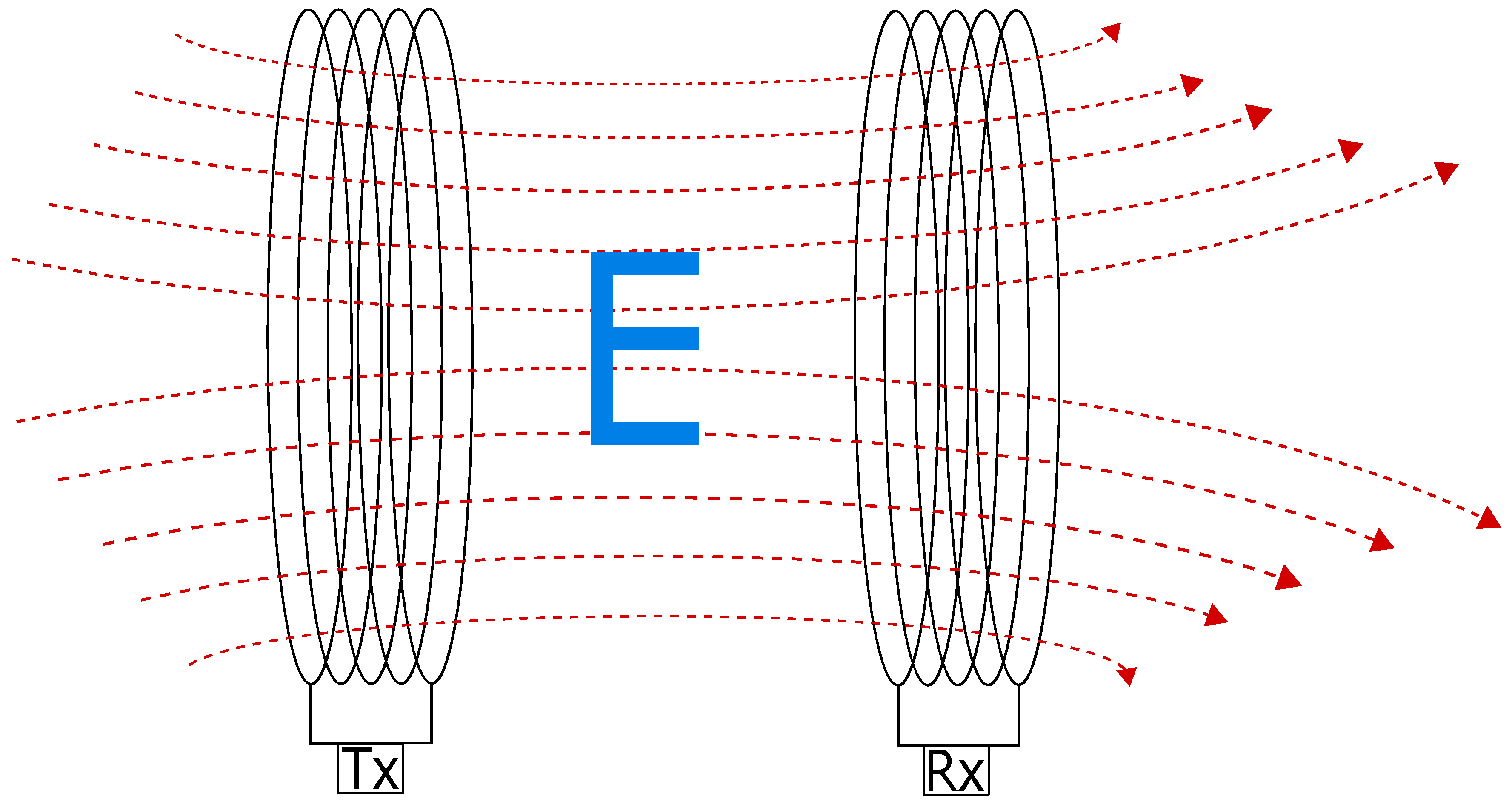
10]. The power is delivered wirelessly over the air gap, however most of the chargers use plastic or metal cover. The transmitter reaches the charging device via an electromagnetic field as presented in
Figure 1 [
11,
12,
13].
The need for an industry standard for WPT emerged with the increasing popularity of WPT charging devices. As an answer to that a wireless power consortium has introduced the QI standard [
14,
15,
16]. The standard was adopted for both low and medium power transmission, and it allows to charge the device with the power of up to
. Increasing both the power transmission efficiency and the distance between the coils plays a vital role in the development of WPT systems [
17,
18]. The efficiency of the system is highly dependent on distance and the alignment between the transmitting and receiving coils [
19,
20]. Over the past few years, many techniques have been applied to optimise the transfer efficiency over low coupling factor [
21]. Compensation topology and circuit analysis play the most fundamental role in the design of resonant WPT systems [
22]. To improve the system distance, high quality factor (Q) of the coil is a crucial element [
23], however this requires the coil to have much higher inductance over capacitance, and therefore increased value of the Q makes the coil bulky [
24].
Also, it is important to note that the QI standard is not suitable for higher power applications such as electrical vehicle charging [
25,
26,
27]. QI technique uses loosely-coupled loops, however, with the use of strongly-coupled magnetic resonance (SCMR) technique researchers were able to achieve much higher transfer efficiency at smaller coupling factors [
28,
29]. Critically coupled resonators can be used in order to gain highest efficiency of the SCMR system [
30,
31]. Quality factor of the coil plays a crucial role in achieving high efficiency at low coupling factor, therefore the inductance of the coil must be relatively high in relation to the capacitance [
32,
33].
The size of the WPT system has gained widespread popularity among researchers, since the market interest of being applicable to real time problems increased. Researchers have made numerous attempts towards the reduction of the coil size [
34,
35]. In [
32], the use of embedded loops in a SCMR system has been suggested by the authors. Conformal SCMR (CSCMR) system indicates a significant reduction of the size of four-loop systems. Authors in [
36] have also suggested using metamaterial arrays and a three coil system to further reduce the size of the receiver. Series-series connected resonant capacitors with a double current rectifier, has been proposed in [
37]. Furthermore, according to the authors this method simultaneously reduces the current in the secondary coil while the physical parameters of the coil are reduced. A significant reduction of 38% of a total coil weight has been gained in [
38], where the authors proposed a selective harmonic approach of the transfer frequency.
In this paper, we explore the possibility of introducing a new set of inductors to the existing transmitter and receiver structure in order to further reduce their size. While the new technique reduces both the size and the weight of the coils with minimum compromise in efficiency, it further reduces the amount of the material used for the circuit simultaneously leading to minimised production cost. This will make the resonant WPT system more desirable in handheld applications. The contributions of this paper are as follows. Initially, the analytical model of the newly proposed system with additional inductors, indicates that the system reaches its maximum efficiency at a lower coupling coefficient. In addition, the relationship between the size of the new inductors and the coupling factor needed to reach maximum efficiency is studied. Also the effect of the resistance of additional coils on the system efficiency is investigated. The second contribution of this work resides in conducting experiments in order to validate the analytical results. Furthermore, a novel concept of designing a two-loop resonant WPT circuit is introduced, where instead of using resonant inductors with a high resonant factor, a set of small inductors is placed in parallel with an inductor of a low quality factor. The technique allows the newly formed WPT circuit to reach its maximum efficiency at similar or even smaller coupling factor as the circuit with the coils of high quality. Results demonstrate that the proposed system is able to achieve similar efficiencies as the system with larger coils at similar distances, interestingly, with further reduction in size and weight. This further indicates that the high quality of the system can be achieved without higher inductive coils and specific, lower capacitors value.
The rest of the paper is structured as follows.
Section 2 describes the proposed model and presents the mathematical analysis providing an insight into the subject using multiple theoretical equations, while the system specifications and numerical results are presented in
Section 3. In
Section 4, the experimental parameters and the system configuration are described in details. A comparison between the calculated and the measured coupling factors needed to reach the maximum efficiency is made in
Section 5. Finally, the conclusions are drawn in
Section 6.
2. Theoretical Analysis of Strongly-Coupled WPT Systems
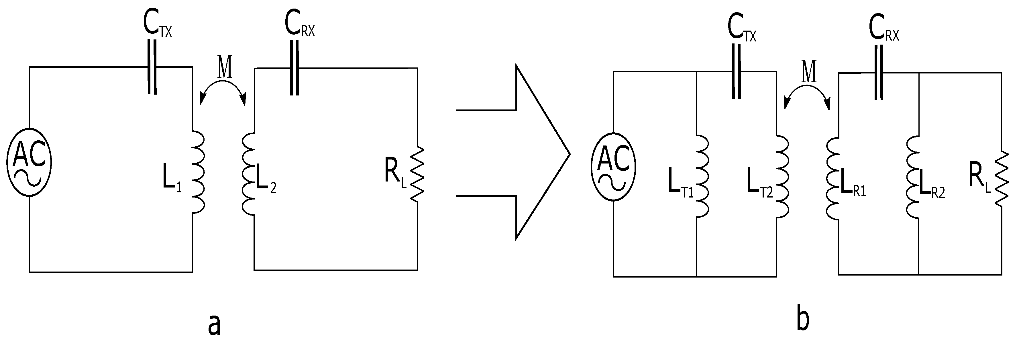
In highly resonant WPT systems the resonators must have a high resonance factor in order to transfer energy efficiently across the gap between the transmitter and receiver coils. When two resonators are placed close to each other they form an inductive link which allows them to transfer energy via mutual inductance (
M), as shown in
Figure 2a. The electromagnetic field (
H) between the two loops can be derived from Ampere’s law and Faraday’s law of electromagnetic induction [
39] as:
where
represents the current in
xth loop,
is the radius of
yth loop, while
d represents the distance between the two loops.
As shown in
Figure 2b, the proposed system introduces two inductors in parallel with an existing inductor. The newly added inductors are minimised in size and are positioned in the circuit in a way to have no effect on the mutual inductance link between the transmitter and the receiver coils.
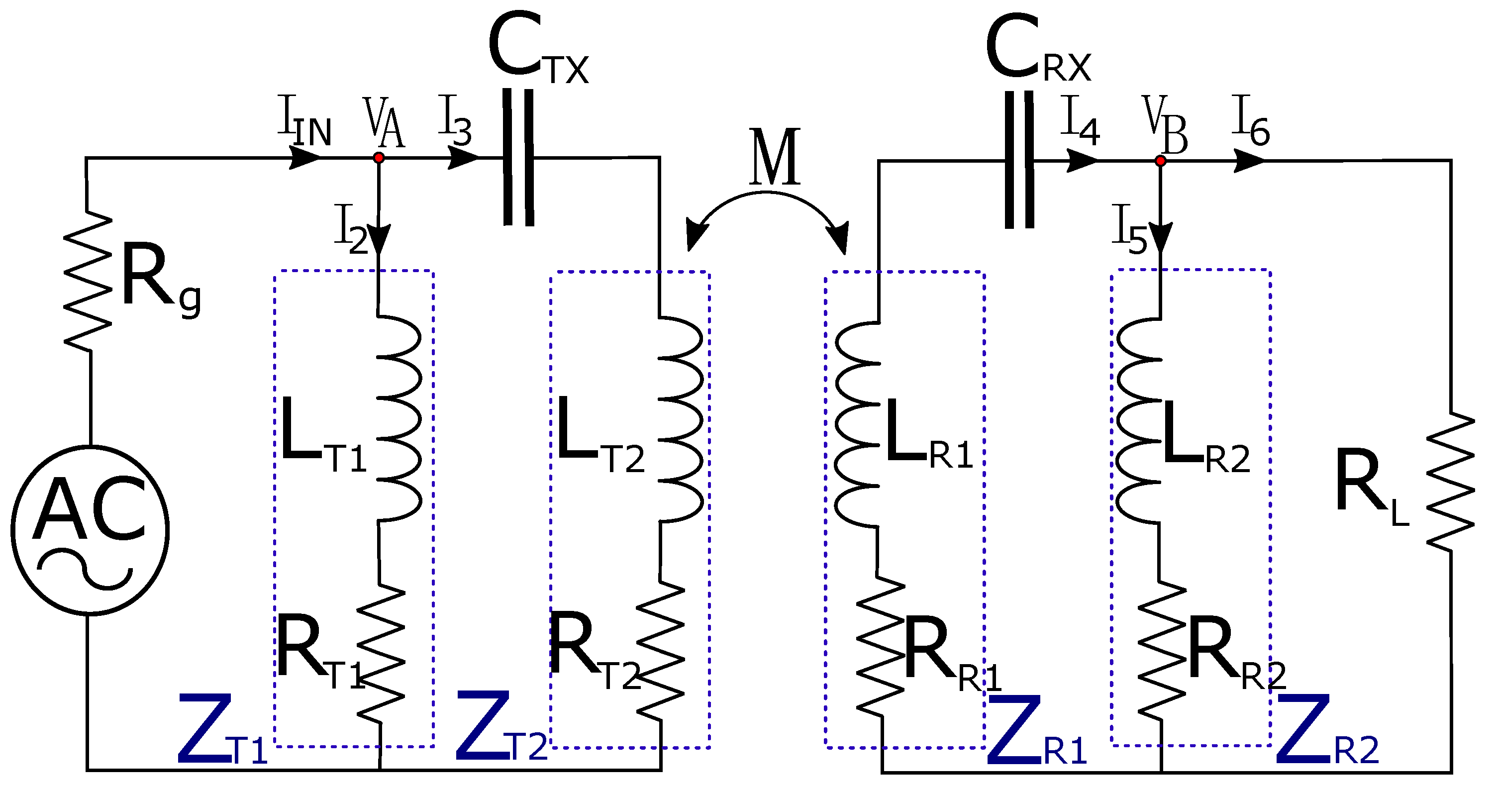
The WPT circuit model of the proposed topology is presented in
Figure 3. In addition to the existing LC resonant loop, this method introduces two additional inductors, one on each side of the WPT system. At the transmitter side, the new inductor
is placed in parallel to the pre-existing LC oscillator and forms a new LCL circuit design. Similar to the transmitter side, the receiver has a new inductor attached in parallel with preexisting LC circuit and forms a new LCL oscillating circuit on the receiver side. The two newly formed oscillators determine the oscillating frequency of the WPT circuit, at which the transmitted power will be maximised. In addition to the two inductors
and
, the circuit contains a frequency generator (AC) used as a power source and its input is a sine-wave voltage, while RG represents the internal resistance of the frequency generator.
and
are the transmitter and receiver capacitors which together with
,
,
and
form the LC oscillator. It is important to note that the real inductor already has some self capacitance reduce value and therefore the loop already has its own oscillating frequency. However, in order to reduce magnitude of the current and increase the magnitude of the voltage, compensation capacitors must be added [
18].
,
,
and
represent the internal resistance of the used inductors.
To analyse the circuit, all branches currents and voltages should be determined. At the transmitter side the represents the input current. The current is divided into two currents, and based on Amperes law ( = + ). Voltage represents the voltage on the T-node at the transmitter. At the receiver side, represents the induced current through mutual inductance (M) from the transmitters coil to the receiver coil , the current is further divided into two currents and ( = + ) while represents voltage at the T-node at the receiver side. represents the resistance of the load, while , , and are the impedances of the inductors. The impedance is calculated as = + j, where represents an internal resistance of each inductor, and represents inductance.
The energy normally oscillates between the coil and the capacitor. The angular frequency at which the energy oscillates can be mathematically calculated as
. However, in the proposed design the additional coil is introduced, therefore the energy oscillates between the capacitor and the two inductive coils, and can be expressed as:
A desired oscillating frequency of the system can be adjusted with the size of inductor and capacitor, however in order to achieve higher distances a high quality factor is required. The quality factor can be calculated as:
High quality factor of the resonators is crucial for a high-resonant WPT system to achieve high efficiency. Resonators are usually made to have a relatively narrow frequency band which reduces their chance to interact with other objects. However, in order to achieve a high quality factor high inductance is required, that increases the size of the transmitter and receiver loops. In order to reduce the size of the transmitter and receiver loops, a new concept of design is proposed. With the LCL design herein described, in which the inductors are placed in a way that only
and
inductors interact with each other, similar results can be obtained. In order to analyse the circuit of the proposed system, the following set of equations can be derived from the proposed circuit in
Figure 3, and the currents in the circuit can be mathematically described as:
and the voltage
can be written as:
while the voltage
is:
In order to reduce the complexity of the calculation, the following part of the equation has been simplified:
Therefore, from these equations the input impedance
can be calculated as:
where
The efficiency of the system
, can be calculated as:
Therefore, the efficiency of the proposed circuit could be expressed as follows:
where
k,
l,
m,
n,
o and
p are:
G is gain for the circuit and can be expressed as:
where
q and
r can be described as:
and the
o,
p,
q and
r are:
3. Numerical Analysis
The transmission efficiency and the distance at which the system achieves maximum efficiency strongly depends on the geometrical design of the loops [
40], and can be calculated as:
In order to compare the results between two designs, all four loops which oscillate at the same frequency have been designed to have the same inner diameter. The inner diameter of the transmitter and receiver loops were set to be at 72 mm and the frequency at which they oscillate was set at 9.23 MHz. However, as presented in (19), an inner diameter of the loops can be chosen as desired, without affecting the results. If the inner diameter is reduced, the maximum efficiency will be at the same coupling factor between the two loops as for the larger system. The additional loops (, ) have a diameter of 2 mm, however, they do not affect the mutual inductance between the transmitter , and receiver coils.
3.1. High Q Coil System Specifications
According to (3), the requirements that determine the Q of the coil are low resistance of the coil and high ratio between the inductance and capacitance. However, the combination of the inductor and capacitor plays a vital role in determining the oscillating frequency. Therefore, to calculate the parameters of the high Q loop, Equation (
2) has to be considered. Calculated values of the elements used in high Q circuit are presented in
Table 1. The inductance of the transmitter loop (
) is set at 186.6
H while the required capacitance is
= 1.6 pF. For the receiver loop, the inductance
is set at 229.6
H while the capacitance of the receiver is
= 1.3 pF. The internal resistance of the coils is 0.15Ω whereas the resistance of the source and load is equal to 50Ω.
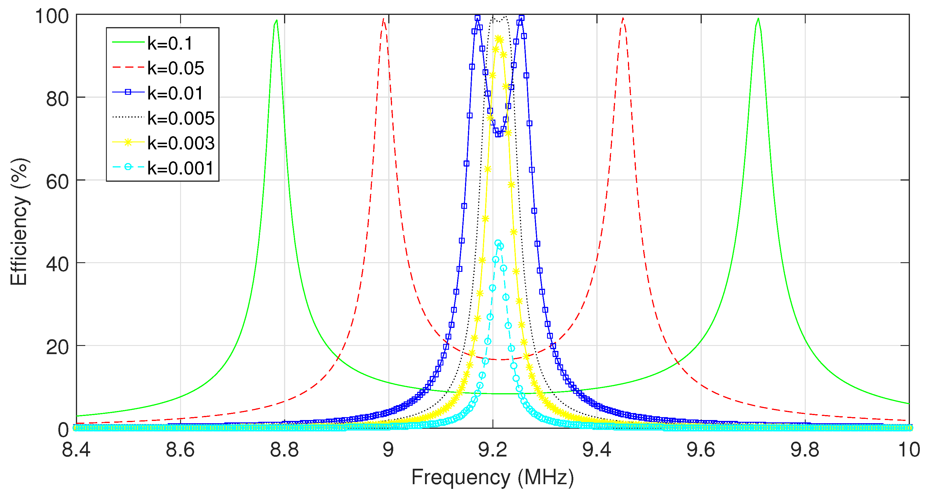
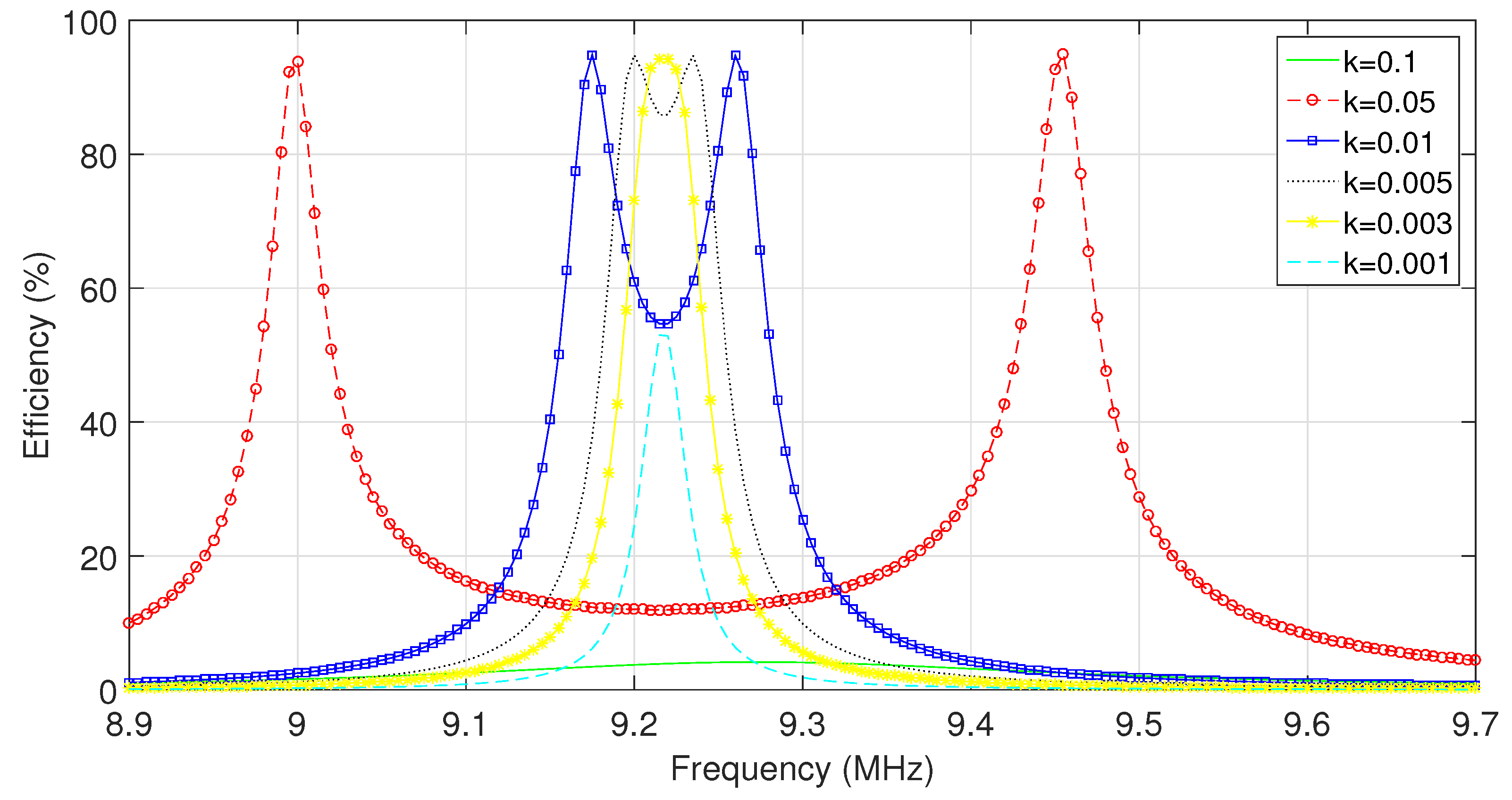
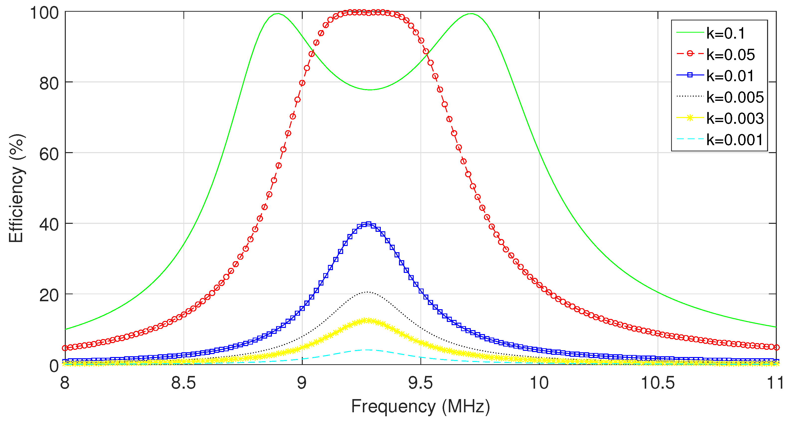
The simulation results of the above circuit are presented in
Figure 4. It is shown from the figure that when the coupling factor between the transmitter and the receiver is 0.1, the circuit is over-coupled. The maximum efficiency appears at the frequency of 8.79 and 9.71 MHz. The maximum efficiency of the circuit appears when the coupling factor between the transmitter and receiver is 0.004 and after optimum coupling factor is reached the efficiency starts to decline. When the coupling factor falls to 0.001, the maximum efficiency declines to 43%.
3.2. Low Q Coil System Specifications without Additional Inductor
In contrast to the high Q system, the loops in this system do not require a large capacitance and inductance ratio, as presented in
Table 2. In order to make the system more cost-effective, standard widely available 15 pF and 18 pF capacitors were used in this experiment. The capacitance value for the system with Low Q coil is much higher that that of the capacitors used for high Q design, however the market price per unit is similar. Therefore, to make the loops oscillate at the same frequency as the system with high Q inductors, the transmitter loop must have inductance of 16.37
H and 19.65
H, respectively. The resistance of the inductors is the same as the resistance of the loops with high Q, 0.15Ω.
In
Figure 5 the calculated performance of the system is presented. As shown in this figure, the system reaches maximum efficiency when the coupling factor between the transmitter and receiver is equal to 0.05, which is far higher than the coupling factor required to reach maximum efficiency with high Q of the coil at 0.004. The system with low Q factor reaches efficiency of
at the coupling factor of 0.003, which is equivalent to
reduction compared to the previous system.
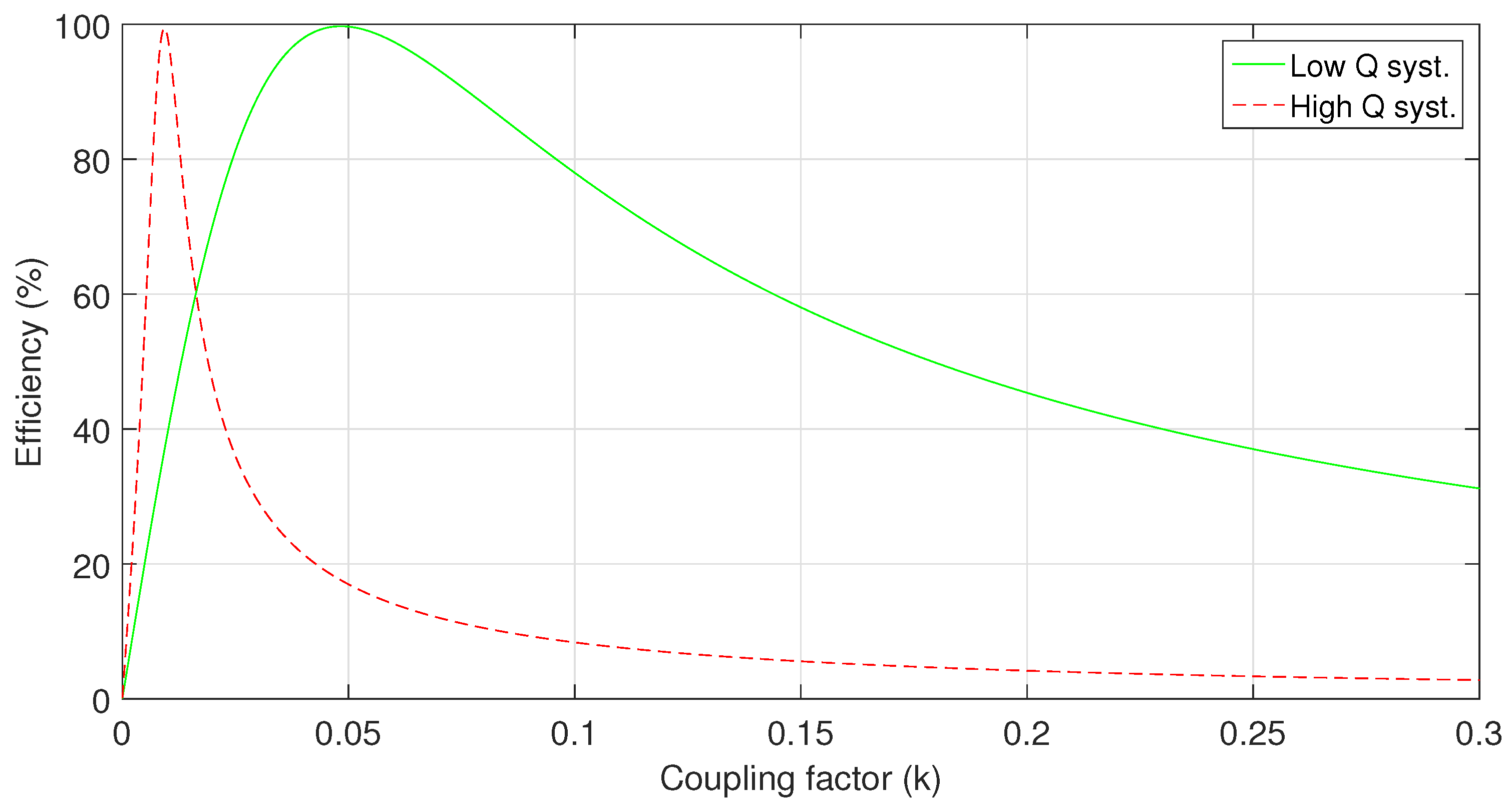
As mentioned earlier, the quality of the coil affects the coupling factor needed for the system to reach maximum efficiency. In
Figure 6 the difference between the two systems is presented. It is evident that the system with low Q value requires higher coupling factor to gain its maximum efficiency. However, the system designed with high Q value has its maximum efficiency at the coupling factor of 0.004 while the system with low Q coils obtains maximum efficiency when the quality factor is 0.05.
To enhance the performance of the system with low Q coils, two new inductors are introduced to the existing WPT system. The inductors
and
are connected in parallel with the transmitter and receiver loops, (
,
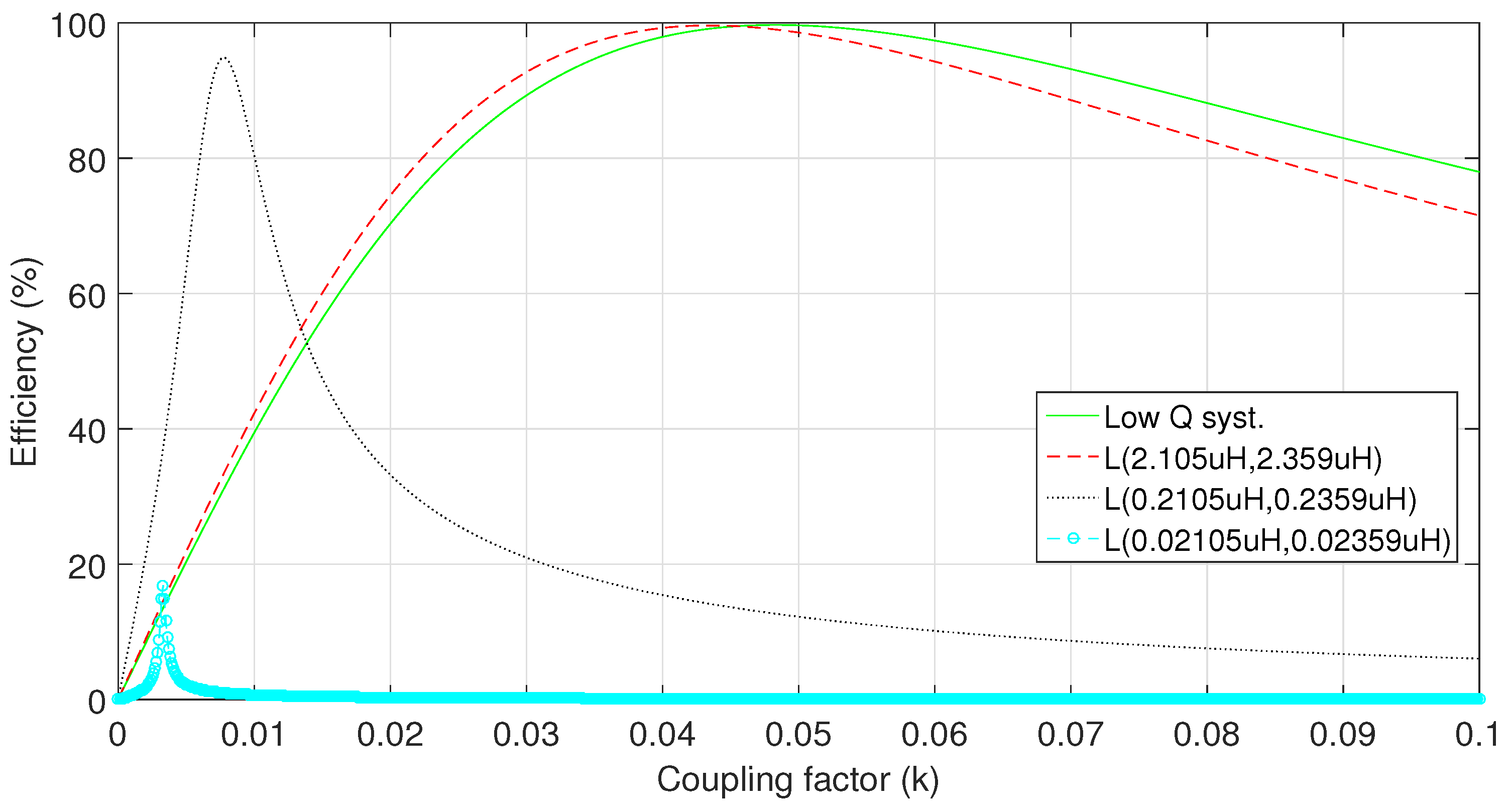
). In order to determine the size of the additional coils, the graphical presentation of the effect is presented in
Figure 7. It is shown that the increase of the value of the additional inductors connected in parallel to the resonator coil increases the coupling factor needed to maximize the efficiency. If
= 2.105
H and
= 2.359
H, the difference between the coil with additional inductors and low Q coil is minimal. Conversely, if the additional inductors values are too small, as shown in the figure where the
= 0.02105
H and
= 0.02359
H are used, the maximum efficiency drops drastically.
The size of the additional inductors has to be chosen based on the numerical analysis. In this case, we chose to use
= 0.2105
H and
= 0.2359
H which offer a performance close to that of the system with high Q of the inductor, as shown in
Figure 8. To maintain the oscillating frequency of the system at 9.23 MHz and to use the widely produced capacitors, a tradeoff in performance is required. Therefore, the designed system reaches the maximum efficiency at k = 0.003, while the system with high Q factor reaches its maximum at k = 0.004.
The system specification of the elements is presented in
Table 3. As it can be seen, the system is a combination of the low Q coils and the additional coils. The calculated performance of the system is presented in
Figure 9. As shown in the figure, the system reaches a maximum efficiency of
when the coupling factor between the transmitter and receiver is 0.003. This presents high improvement over the system with low Q coils which reaches maximum efficiency at k = 0.05. However, an efficiency drop is a major drawback which is a reasonable trade-off in order to reach larger distance without affecting the coils size and weight.
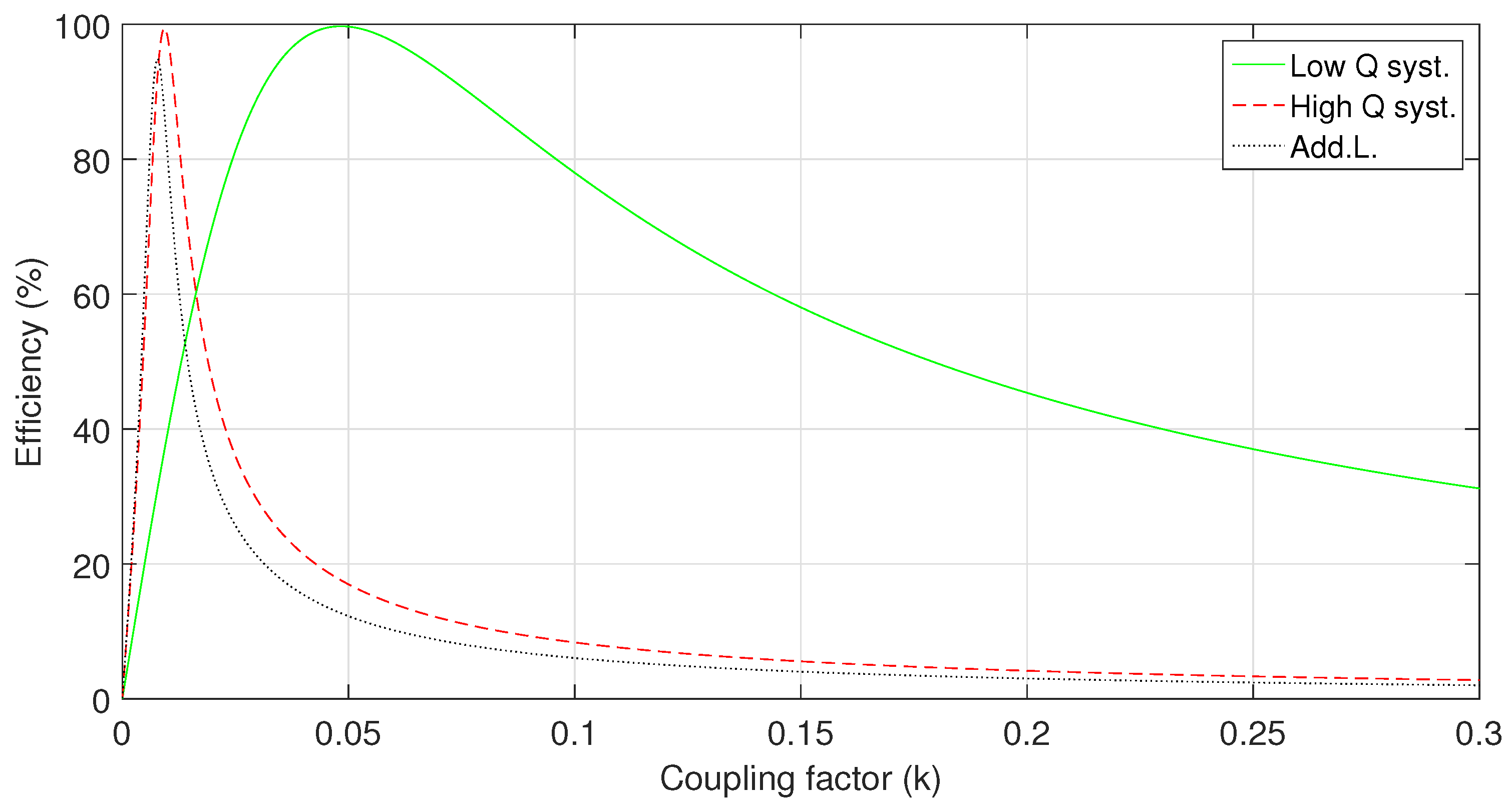
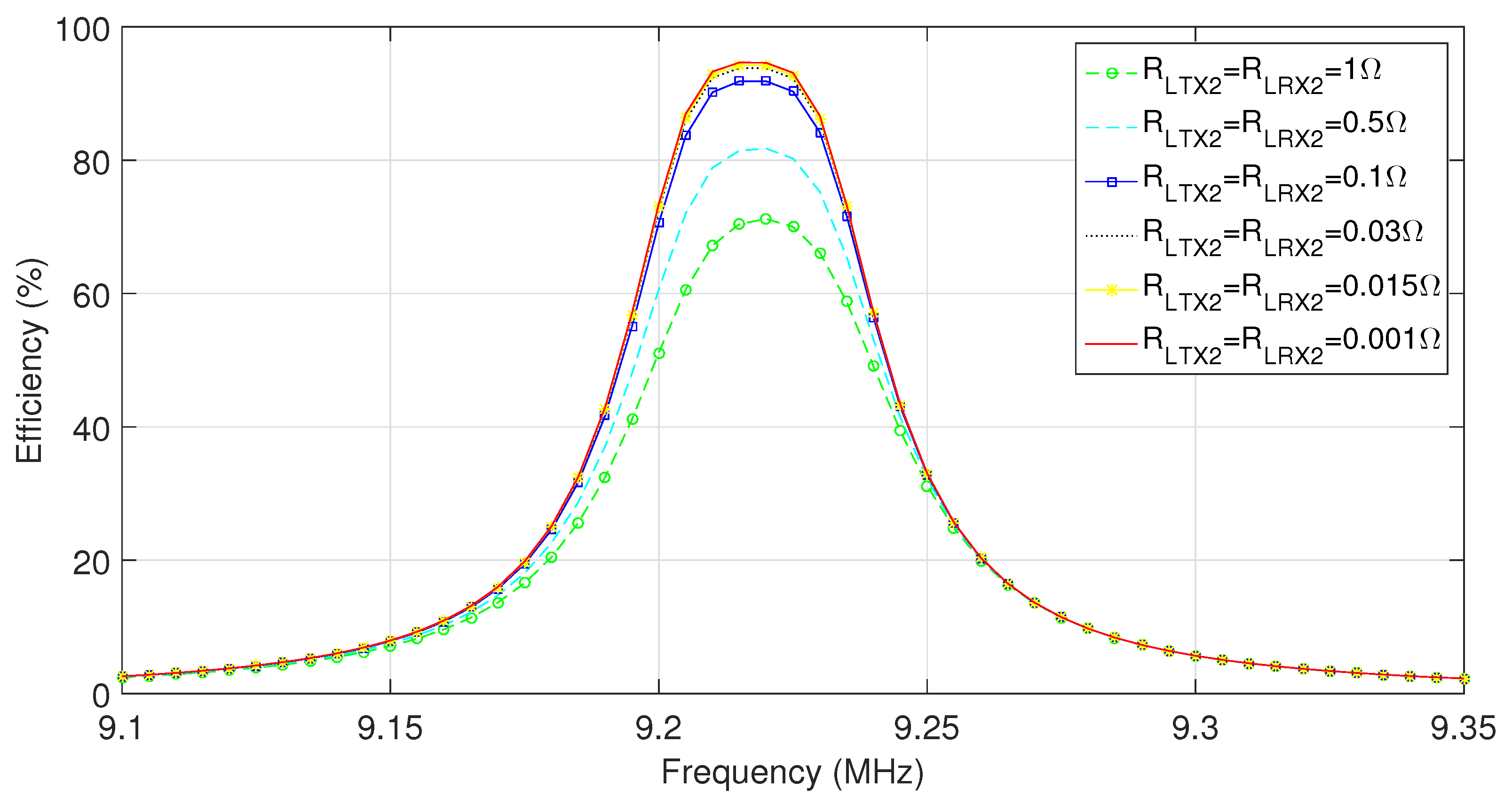
3.3. Effect of the Additional Coil Resistance on the System Efficiency
The resistance of the added coils
and
has an important impact on the maximum efficiency thus has been analytically determined via mathematical calculations, which has been the base of the
Figure 10. It can be seen that increasing the resistance of the added inductors has a negative effect on the transmission efficiency. When the resistance of the added coils increases from 0.1Ω to 0.5Ω, the system efficiency drops by 10%. A further increase in the coils resistance to 1Ω leads to a drop of efficiency by additional 10% to 70%. From the figure it can be concluded that the increase in resistance leads to a rapid decrease in the system efficiency. However, in the opposite direction, when the resistance decreases, the efficiency improves. As seen from the graph, when the resistance decreases from 0.1Ω to 0.001Ω, the efficiency of WPT system increases by 1%, to 95%. Therefore, in order to reach high efficiency, maintaining a low resistance of added coils
and
is a crucial factor.
5. Results
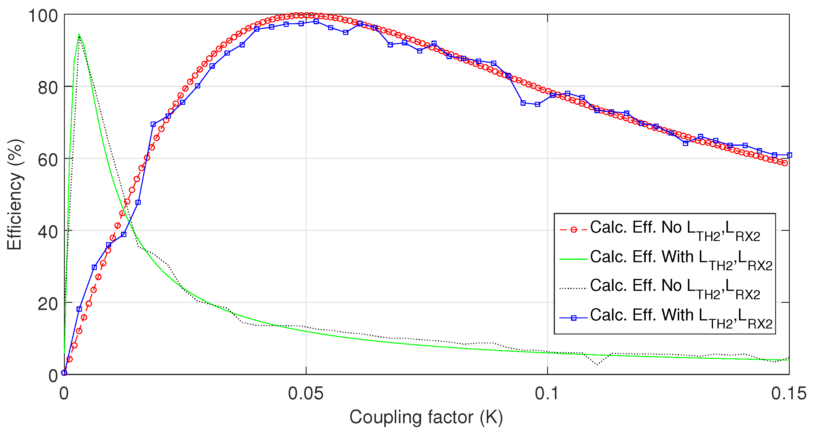
The maximum distance at which the system is able to deliver power with high efficiency is a crucial factor in any WPT system. Up until now a high quality factor of the transmitting and receiving coils was required to efficiently transmit the power on small coupling factor between the two coils. With the proposed method for the maximum distance of the transmission, the quality factor of the transmitting and receiving coils can be made smaller. As shown in
Figure 13 the maximum transmission efficiency between the two coils with low quality factor occurs when the coupling factor between them is equal to 0.05. However, the same two coils can achieve larger maximum distance for the power transfer with the addition of two small inductors
and
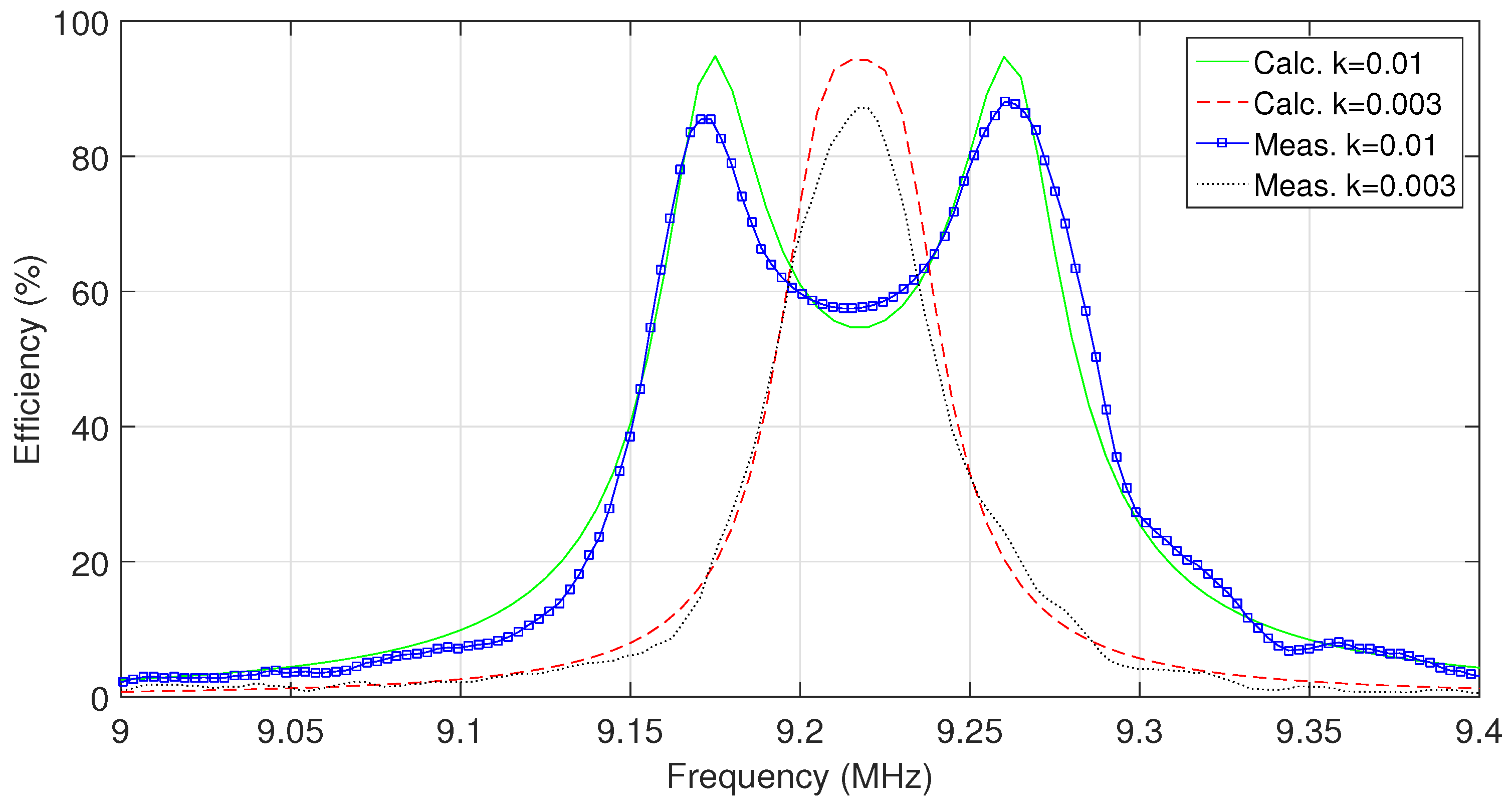
in parallel with the existing inductors. The maximum power transmission between two coils in that case occurs when the coupling factor between the two coils is equal to 0.003, which significantly improves the maximum distance. In both cases, calculated results are compared with the measured as illustrated in
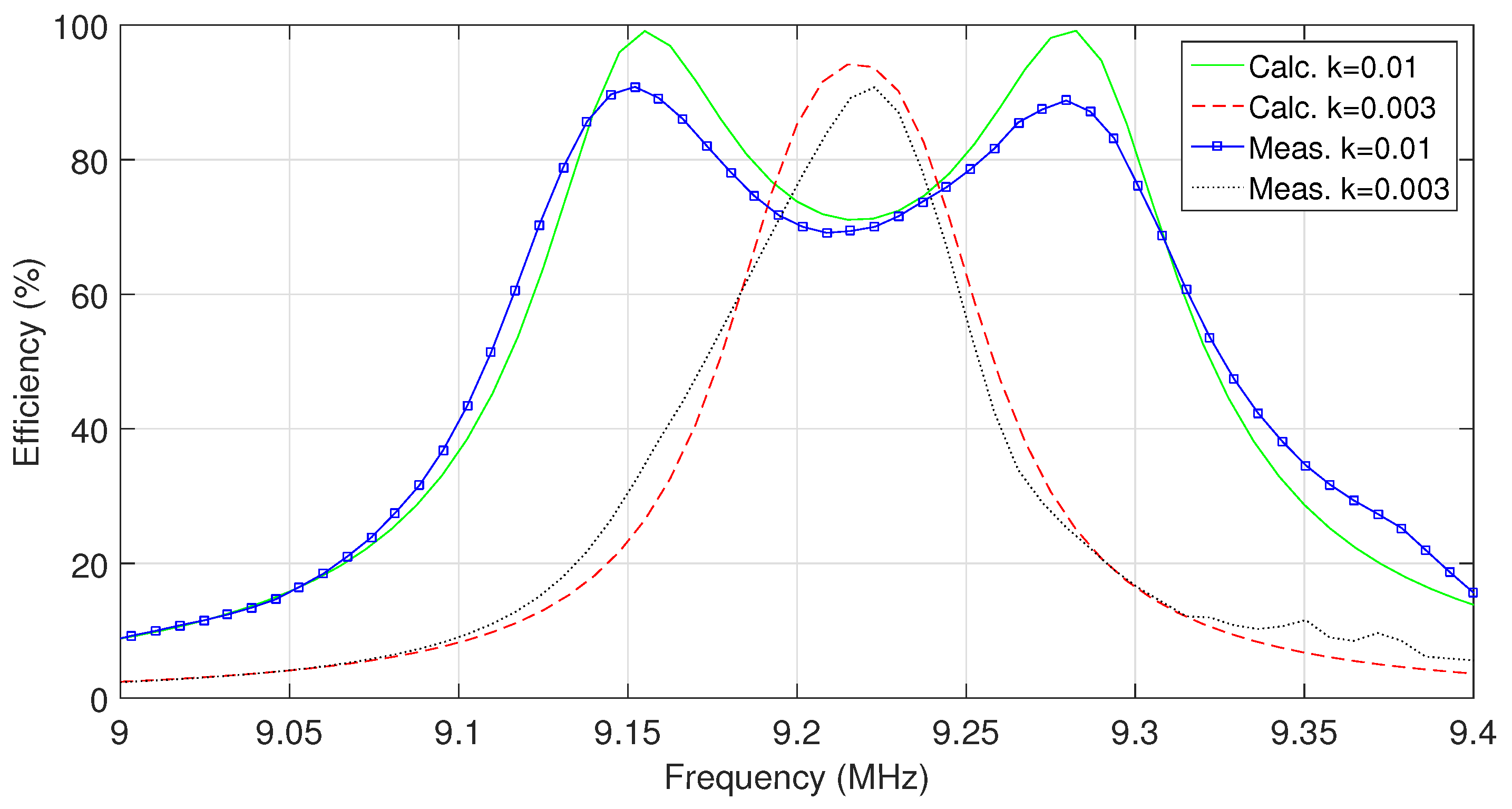
Figure 14. It is shown that the maximum efficiency of the two systems appears close to the calculated results.
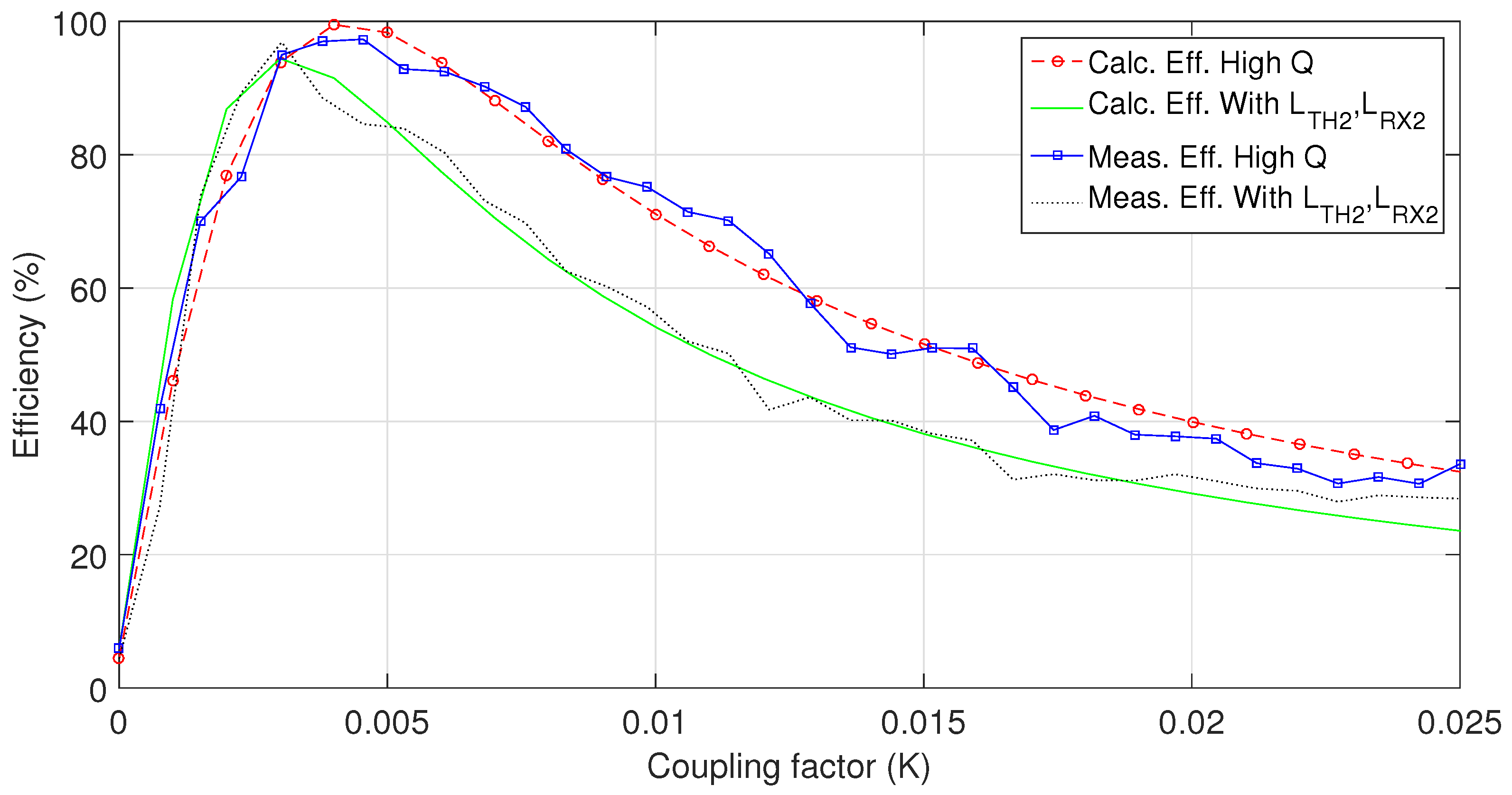
Similar to the system with low quality of the coils, the new proposed system is compared with the conventional system with a high quality of the transmitter and receiver coils.
Figure 15 shows a comparison between the two. As seen from the figure the system with high quality coils reaches its peak when the Q between the two coil reaches 0.004 and the maximum efficiency of the proposed design is reached when the coupling factor between the two coils is 0.003. As already mentioned, this occurs due to a desire to use widely available values of the capacitors. From the figure, we can see that the measured results from the prototype system closely follows the calculated results from the model. From the calculations, the maximum efficiency of the proposed system is 7% below that of the conventional model, however the advantages of the proposed design are shown in
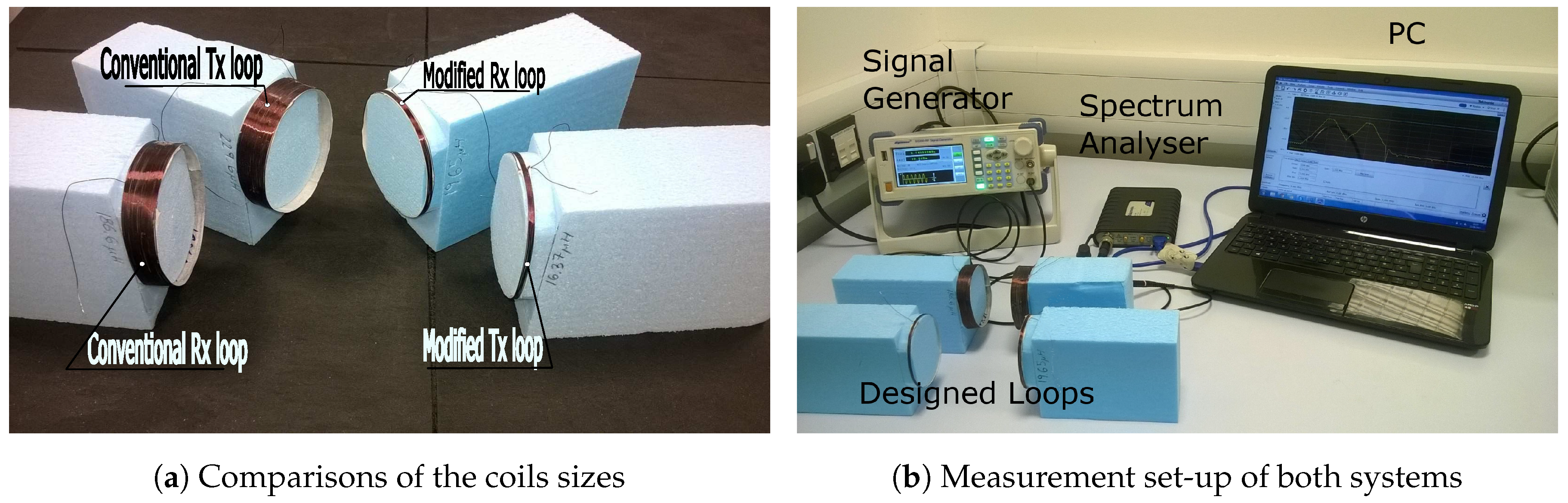
Table 4.
The main advantage of the proposed design is the reduced size of the loops. The length of the transmitter loop in the conventional design is equal to 15 mm while that of the proposed design is equal to 3 mm. Similar to the transmitter loop, the length of the receiver loop from the proposed design is 4 mm, which is a big improvement from the 20 mm required for the system from conventional design. Furthermore, the proposed system design has significantly reduced the weight of the WPT transmitter from 7.37 g in conventional system to 1.58 g while the receiver weight also improved from 8.63 g to 1.78 g. Both of the above advancements has lead to overall 80% reduction of its size and weight. Therefore, the size reduction offered by the proposed system is achieved at the cost of slight reducing the system efficiency.

 ,
, 


