Article

Field-Weakening Performance Improvement of the Yokeless and Segmented Armature Axial Flux Motor for Electric Vehicles

School of Electrical and Information Engineering, Tianjin University, No. 92 Weijin Road, Tianjin 300072, China
*
Author to whom correspondence should be addressed.
Energies 2017, 10(10), 1492; https://doi.org/10.3390/en10101492
Submission received: 10 September 2017 / Revised: 23 September 2017 / Accepted: 25 September 2017 / Published: 26 September 2017

Abstract

:
In order to avoid the unsafe operation and raise efficiency of yokeless and segmented armature axial flux motors at high speed, the control current of air gap flux is expected to be as small as possible with the same field-weakening effect. To reduce the control complexity, a new structure of module poles with a combination of permanent magnet and soft magnetic material is proposed, which has the characteristics of lower d-axis reluctance and a higher performance of yokeless and segmented armature axial flux motor with surface mounted permanent magnet. According to finite element analysis (FEA), the flux distributions of a rotor pole in no-load and demagnetization condition are contrasted, and under this new configuration, the derivative analytical models of back electromotive-force (EMF), electromagnetic torque, and air gap flux are validated, moreover, the influence of soft magnetic material of rotor poles on controlling the air gap flux is investigated in different load. Based on a particular objective function, the combination of permanent magnet and soft magnetic material is optimized. The results show that optimal solution of field-weakening performance of yokeless and segmented armature axial flux motors can be improved effectively and legitimately.

1. Introduction

During recent years, the rising cost of energy and environmental issues have encouraged researchers to investigate techniques for increasing the efficiency of electric drives. Greenhouse gas emissions mainly come from road transportation vehicles, such as cars, vans, and heavy goods vehicles. One way that may solve this problem is to generalize the use of vehicle electrification. In order to be economical in terms of cost, weight and magnitude, while meeting performance and reliability demands, it is expected to maintain payload and not add too much extra weight on the vehicles in the meanwhile. The technology of yokeless and segmented armature axial flux motors was developed specifically for the electric vehicles to solve those economic and technological problems, besides, because of its superior performance, it can be applied to many fields such as renewable energy sources and flywheel energy storage, and it can also be designed as a high pole machine for low-speed energy systems, such as wind and hydro generators [1,2,3].
Yokeless and segmented armature axial flux motor is a new type of axial flux permanent magnet (AFPM) motor. Compared with traditional AFPM motors, it has smaller stator core weight and iron loss, shorter end-windings, and a higher winding fill factor, which facilitate the higher power density and efficiency of the machines. The most significant feature is the structure of stator. The stator is mechanically and magnetically separated without yoke, which can reduce the cost, volume, weight and unnecessary loss of machines greatly. The stator is composed of a number of identical small modules. In these modules, stator shoes and stator bars are stacked by electrical steel sheets or pressed by soft magnetic composites (SMC) materials or other new materials, such as amorphous alloy. The simple windings are wound around the core directly with insulating materials on the surface, so a high fill factor can be achieved. In a word, the new structure of stators plays an important role in improving of power density and efficiency and it also simplify the manufacturing process of yokeless and segmented armature axial flux motor, which makes it an ideal design for electric vehicles [4].
The rotors of yokeless and segmented armature axial flux motors are same as that of conventional AFPM motors. The rotors of most machines are constructed with surface-mounted permanent magnets, the d-axis inductance is approximately equal to the q-axis inductance, their numerical value is very small, and the reluctance of the d-axis magnetic path is high. All of these features have caused some difficulties in vector control, and for permanent magnets also pose a risk of irreversible demagnetization. At the same time, an excessive increase of d-axis current can lead to an increase of total losses, and thus lower efficiency of machines can result. The method of replacing a part of the permanent magnet with a soft magnetic material has been proposed in [5,6,7] improving the field-weakening capacity of AFPM motors. Reference [5] has indicated that soft magnetic materials can provide a low-reluctance magnetic path for armature reaction flux, and with the new structure, the air gap flux can be reduced by 40% under maximum demagnetization conditions. Reference [6] has indicated that the d-axis inductance of AFPM motors is increased under the new structure. After verifying the correctness of the electromagnetic calculations and analysis, [7] has proved that the predicted results are consistent with the experimental results. However, the above researches are limited to traditional AFPM motors without any analysis of the field-weakening capability of yokeless and segmented armature axial flux motors and a quantitative analytical calculation of back EMF, torque and air gap flux. Moreover, the optimum pole configuration is not presented under the new structure.
This paper proposes a new type of yokeless and segmented armature axial flux motor with modular poles, replacing a part of the permanent magnetic material with a soft magnetic material with the shape of rotor poles remaining unaltered. Based on the analytical calculation and FEA, the performance of machines with this new structure under various conditions is discussed. Also, the analysis of the influence of the dosage of soft magnetic materials on the filed-weakening capacity is accomplished. According the FEA results, the rationality of analytical calculation models is verified. After weighing the output performance and field-weakening performance, the optimal value of the objective function is obtained, which can maximize airgap flux control ability.

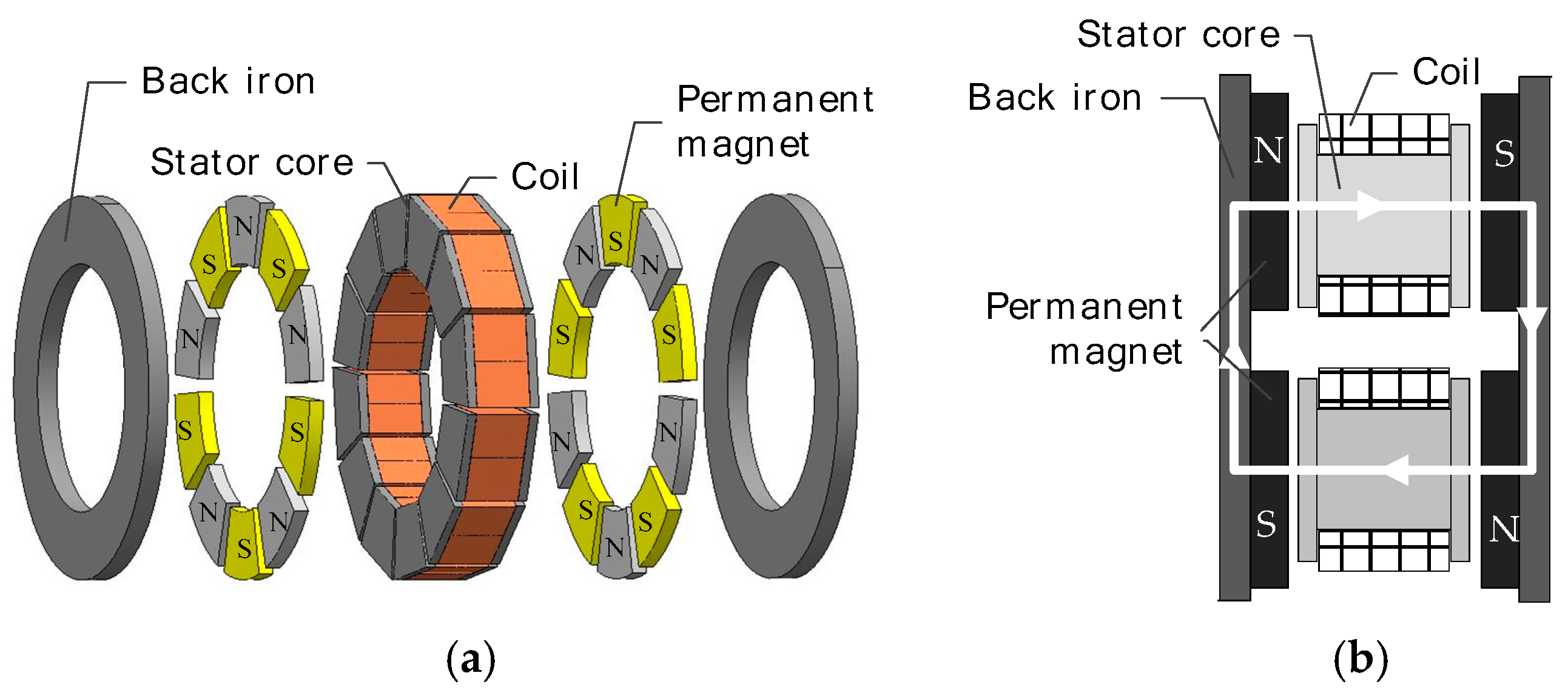
2. Yokeless and Segmented Armature Axial Flux Motors

The surface-mounted yokeless and segmented armature axial flux motor topology is shown in Figure 1. This is a double-rotor, single-stator configuration [8,9]. The stators having coils wound on stator bars are placed in the middle of motor with the construction of yokeless and segmented armature, which are enclosed by an annular stator housing that extends between the air-gap. The stator housing comprises two mating clamshells and each clamshell is moulded from reinforced plastics and interconnected through one or more intermediate components optionally. The rotors having permanent magnets are placed symmetrically on two sides of stator, and the permanent magnet poles are arranged alternately with N pole and S pole and mounted on the surface of each rotor back iron, in addition, the magnetic flux flows along the axial direction. Figure 1b is given to illustrate the closed path of the magnetic path. After passing through the air gap and the stator core along the axial direction, the main magnetic path which departs from the N pole of one rotor reaches the S pole of the other rotor. Then, the path reaches the N pole via the rotor back iron, and it passes through the air gap and stator core along the opposite axial direction. Finally, within an exactly opposite process, the main magnetic path returns back to the N pole of departure side. Therefore, the cost and complication of manufacturing process of the stator bars and stator shoes can be increased greatly if they are stacked by the laminated electrical steel sheets with different sizes. Although the lamination of electrical steels reduces the eddy loss to a certain degree, the loss cannot be avoided anyway because of the high electrical conductivity. Furthermore, the laminated electrical steel sheets can only be used for 2D flux guidance. In comparison with the laminated electrical steel sheets, SMC materials can be pressed into any shape easily with almost no remnant and it suits 3D flux applications with anisotropy [10,11,12,13,14,15]. In this paper, stator shoes and stator bars are manufactured from SMC materials, and the main design parameters are shown in Table 1.

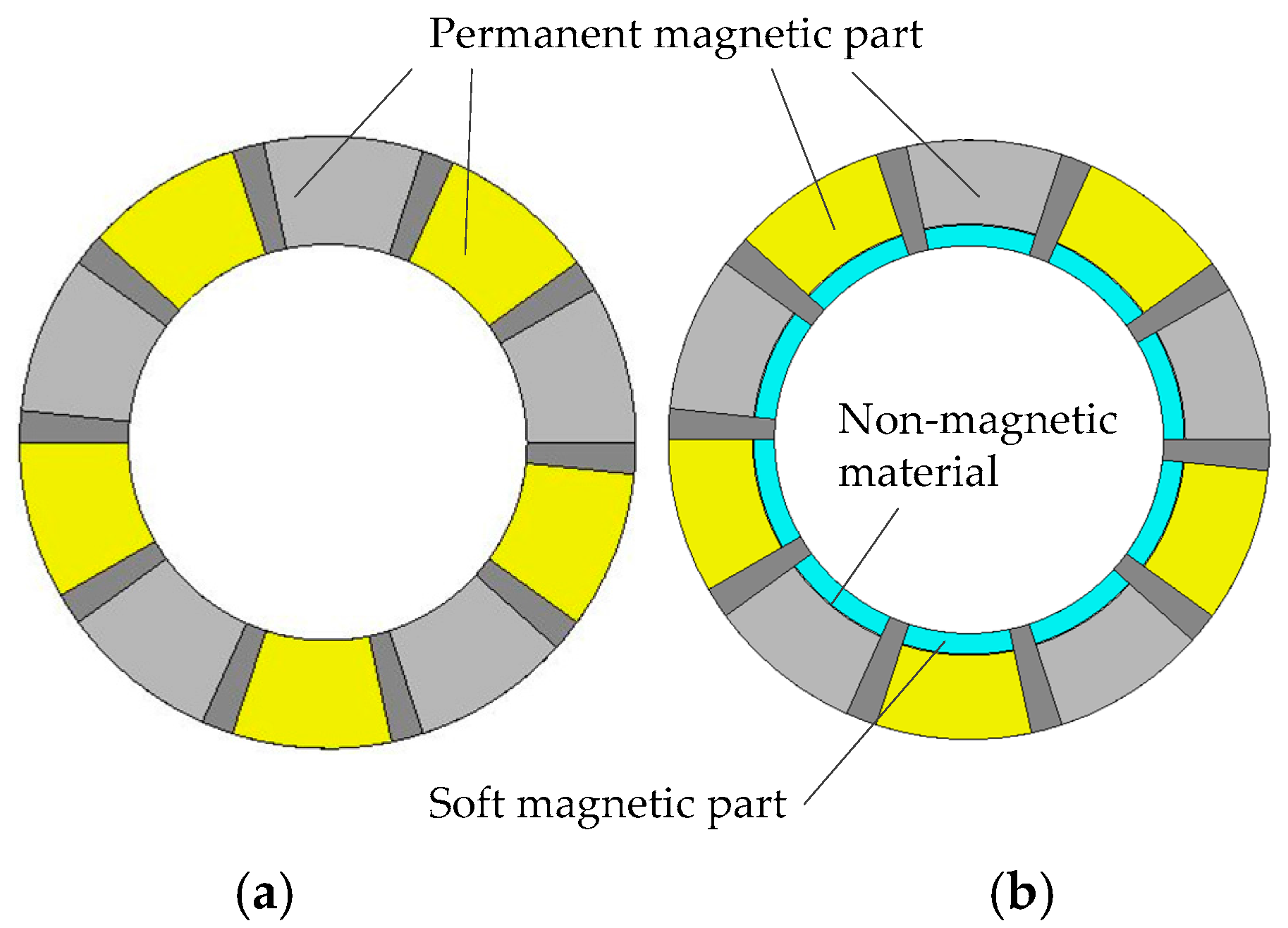
3. New Structure of Rotor Poles

In this section, the structure of rotor poles of yokeless and segmented armature axial flux motor is optimized on the basis of original so as to improve the field-weakening performance. Part of permanent magnet is replaced by soft magnetic materials, thus the rotor pole can be divided into two parts according to material properties. One of them is NdFeB permanent magnet along the rotor outer ring, which is magnetized in the axial direction, as known as permanent magnetic part. Another part is soft magnetic materials along the rotor inner ring, as known as soft magnetic part. Electrical steel sheets or SMC materials can be chosen as the soft magnetic material. In spite of the advantages of SMC material mentioned above, it has low permeability and high cost. Considering of cost and simple shape of rotor poles in this paper, the electrical steel sheets are selected as the materials of soft magnetic part, and they are laminated to reduce the leakage flux on the rotor pole along axial direction. The non-magnetic material layer is inserted between soft magnetic part and permanent magnetic part to prevent the magnetic short circuit which can reduce the utilization of permanent magnet. The optimization of the rotors is shown in Figure 2.
After optimization, the magnetic reluctance of d-axis magnetic path obviously decreases, due to existence of soft magnetic material in rotor inner ring. The current that controls the air gap flux can be smaller than before. The air gap flux is composed of two parts. Neglecting saturation, the magnetic paths of the two parts are independent of each other. One part is fixed flux which is provided by permanent magnet with high magnetic resistance and constant flux source. Another part of the air gap flux is excited by armature reaction caused by d-axis current, and it is generated after the soft magnetic part becomes magnetized. The magnitude and direction of flux are commanded by stator current vector. The flux distributions in no-load and demagnetization condition of a rotor pole are shown in Figure 3.
In Figure 3, the soft magnetic part is not magnetized under no-load conditions, so that the magnetic field direction of the soft magnetic part is disorganized and the magnetic density is relatively low. Under demagnetization conditions, the soft magnetic part is magnetized, so that the magnetic field direction of the soft magnetic part is opposite to that of the permanent magnetic part, and the magnetic density increases significantly. As a result, the total air gap flux can be adjusted controlling the d-axis reaction flux.

4. Effect of the Soft Magnetic Part

The following discussions neglect the effect of winding resistance, saturation and permanent magnet flux leakage and take no account of permanent magnet irreversible demagnetization.

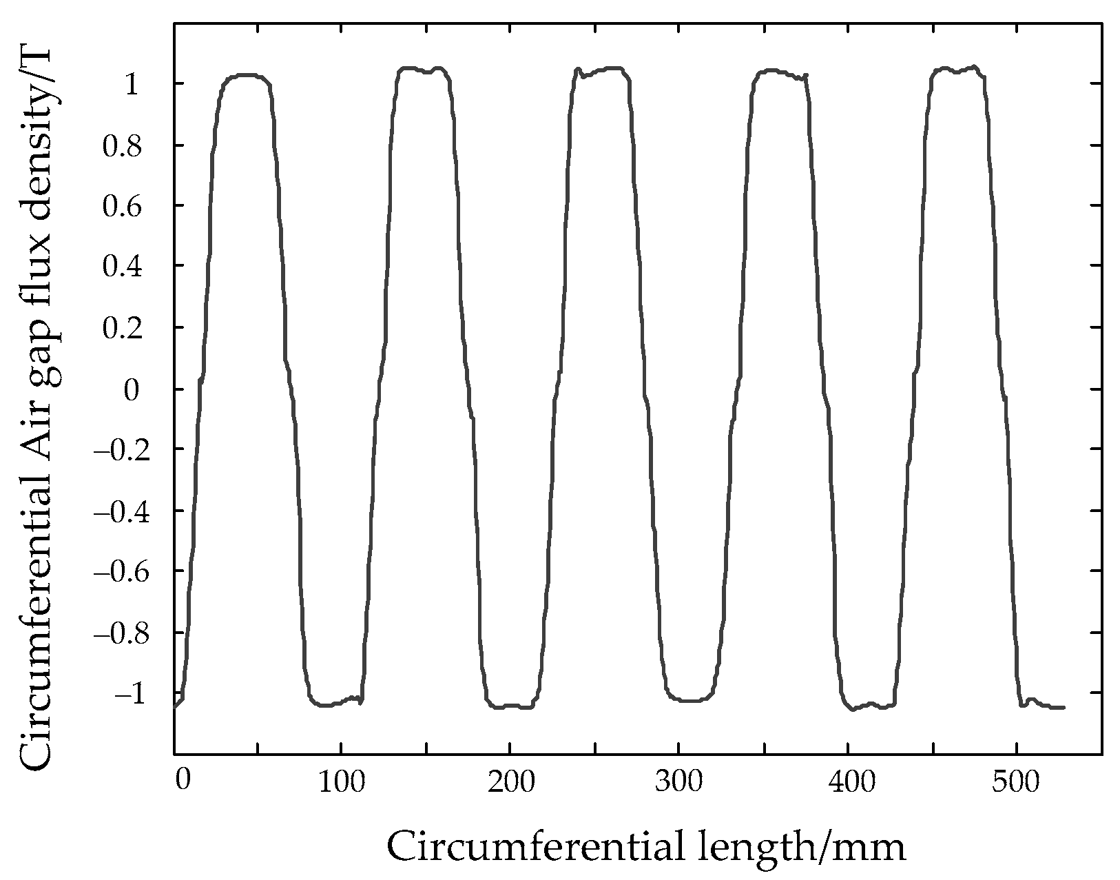
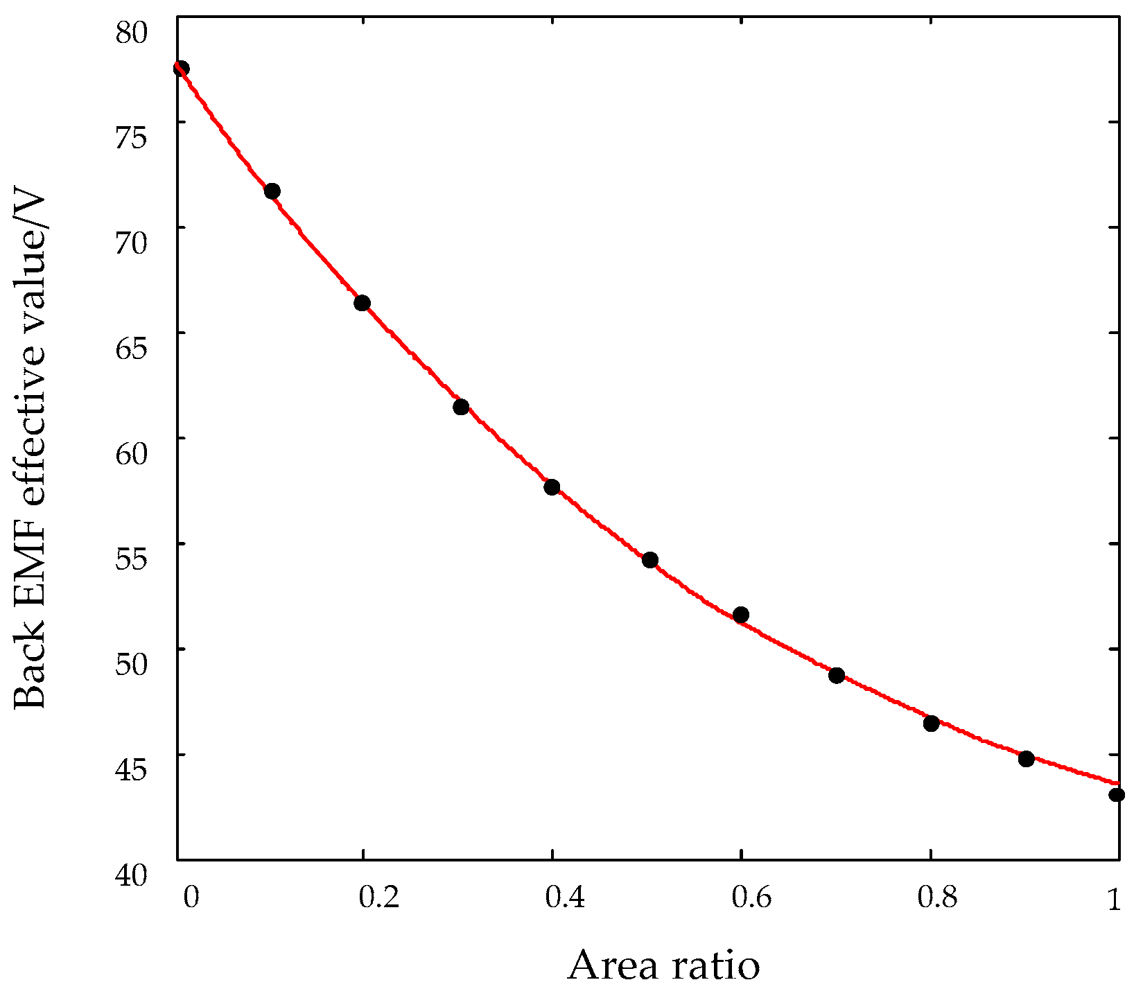
4.1. No-Load Back EMF Analysis

For AFPM motors, the expression of no-load back EMF effective value is:
E = 2 π f N K dp Φ 0
where f represents the magnetic field change frequency, N denotes the winding turns in series per phase, Kdp represents the winding factor, Φ0 is no-load air gap flux per pole.
The existence of a soft magnetic part can offer a low-resistance magnetic circuit for a yokeless and segmented armature axial flux motor, so that the expected effect of field-weakening is achieved, but the reduction of the permanent magnet is going to affect the air gap flux per pole. Therefore, Equation (1) needs to be modified. Under the new rotor pole structure, no-load back EMF can be effectively represented as a function of the soft magnetic part to permanent magnetic part area ratio. This can be written as:
E = 2 π f N K dp K Φ B m S v 1 δ 1 + δ
In the formula above, KΦ and Bm represent the waveform factor and peak value of the no-load air gap flux density, respectively, Sv represents the windings average area. In addition, δ is the ratio of Apm and Asm, Apm represents area of permanent magnetic part face air gap and Asm is that of soft magnetic part. Equation (2) indicates that the back EMF decreases as the area ratio increases.

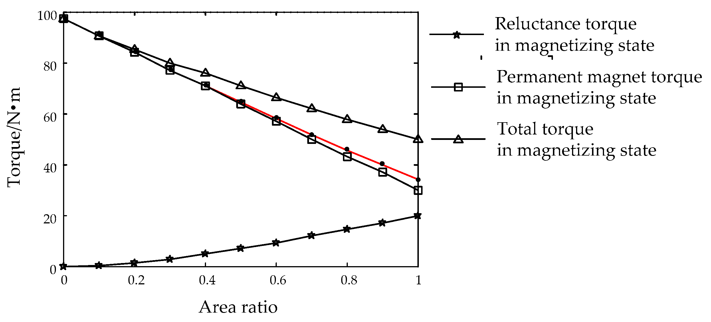
4.2. Electromagnetic Torque Analysis

The electromagnetic torque of APFM motor is composed of two parts: excitation torque and reluctance torque which is caused by the asymmetry of the rotor magnetic path, and the expression is:
T em = p [ ψ f I q ( L q L d ) I d I q ]
In Equation (3), p is pole pairs, Ψf represents magnet flux linkage, Ld and Lq represent d-axis and q-axis inductance respectively, Id and Iq represent d-axis and q-axis current, respectively.
The influence of soft magnetic part for electromagnetic torque, which relates to the amount of the soft magnetic materials, is embodied in two aspects. On the one hand, with the soft magnetic part dosage increasing and permanent magnetic part dosage decreasing, the magnet flux linkage is prone to decline. A successively drop of the excitation torque may result. On the other hand, the increment of the amount of soft magnetic part leads to the increment of Ld, and the remaining value of Lq, which also causes an increment of reluctance torque. By derivation, electromagnetic torque is given in the form of a function of area ratio as:
T em = p { ψ f 0 I q δ [ ψ f 0 I q + ( L q L d 0 ) I d I q ] }
where Ψf0 and Ld0 denote the permanent magnet flux linkage and d-axis inductance for the machine with only permanent magnet in the pole (δ = 0), respectively, and the saliency factor of machines is equal to one (Ld = Lq). Moreover, according to Equation (4), an increment in area ratio leads to a decline of torque with the same stator current.

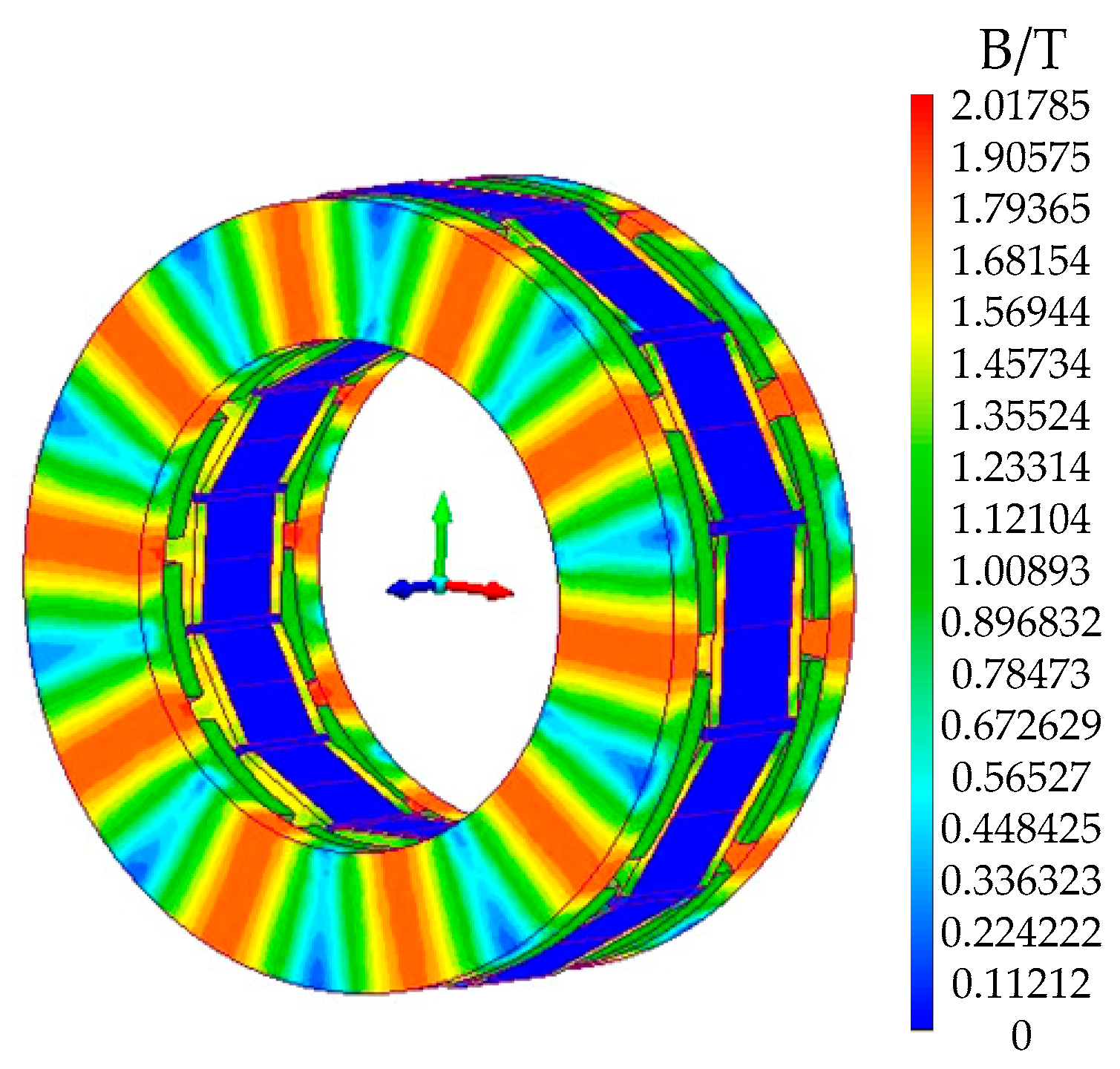
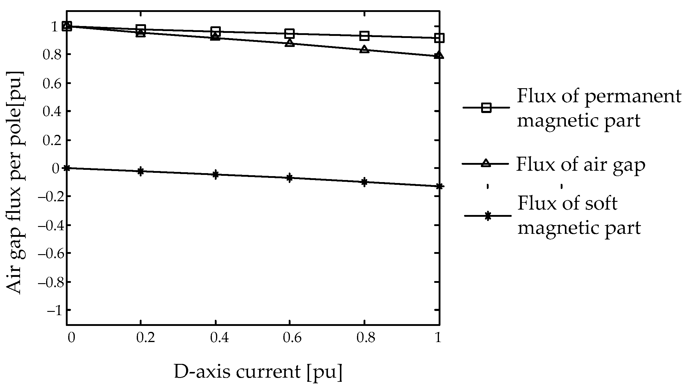
4.3. Air Gap Flux Analysis

The relative permeability of air and permanent magnet is about 1, and their magnetic reluctance is much higher than that of soft magnetic materials. With the analysis of the material properties, the air gap flux along the radial direction is divided into two parts: the flux in front of the permanent magnetic part Φg_pm and the flux in front of the soft magnetic part Φg_sm:
Φ g _ pm = H c L pm R g _ pm + R pm
Φ g _ sm = f m m d R g _ sm
In Equation (6), fmmd is the equivalent d-axis armature reaction magnetomotive force caused by stator current, and Hc represents the permanent magnet coercivity.
The total air gap flux is:
Φ g = Φ g _ pm + Φ g _ sm
The air reluctance of the permanent magnetic part and soft magnetic part can be derived respectively as:
R g _ pm = 2 g μ 0 A pm
R g _ sm = 2 g μ 0 A sm
where g is air gap length, and μ0 represents air permeability. Furthermore, the permanent magnet reluctance is written as:
R pm = 2 L pm μ pm μ 0 A pm
μpm represents the permanent magnet permeability, and Lpm represents the permanent magnet axial length. It is observed that the reluctance in front of the soft magnetic part decreases as the area ratio increases, so that a low-reluctance magnetic path for the armature reaction flux is obtained.

5. Simulation and Optimization Results

5.1. Simulation Anylysis in No-Load Condition

In this section, simulations of yokeless and segmented armature axial flux motors are conducted under no-load conditions, containing 10 groups of machines with the same thickness and shape but different rotor pole area ratios. Figure 4 and Figure 5 are obtained when the area ratio equals 0. Figure 4 illustrates the flux density distribution of the prototype machine. Figure 5 shows the air gap flux density curve at the particular position where the radius is 84 mm, which is the average value of the radius of inner ring and outer ring, and the result shows that the no-load air gap flux density is over 1 T.
To verify the accuracy of the analytical expression (2), the simulation of no-load back EMF is conducted for the same rotor pole shape and thickness. The curve of the back EMF effective value under different area ratios of soft magnetic part to permanent magnet part is shown in Figure 6, and the analytical calculation results which are represented by the red curve are quite consistent with the results of finite element simulation which are shown as black dots. The result of the finite element simulation demonstrates the accuracy of the analytical calculation. Apparently the value of back EMF descends as the area ratio increases, which is concerned with the reduction of air gap flux. An excessive decline may have an adverse impact on the operation of machines under base speed.

5.2. Simulation Analysis in Rated-Load Condition

In comparison with a traditional AFPM motor, the iron of yokeless and segmented armature axial flux motors can be cut nearly 50% because of the particular structure of yokeless stators [16], resulting in a great reduction of the total losses. That is to say, the high efficient output of machines can be ensured when the injected current density of windings is higher than the conventional value. In this section, 10 groups of yokeless and segmented armature axial flux motors in rated-load condition are simulated, keeping the shape and thickness of rotor poles unaltered as the area ratio varies, and it is assumed that the current density of stator windings maintains a constant value of 16 A/mm2.
As discussed in the previous section, to prove the rationality of the analytical expression (4), the simulation of rated torque is conducted with the preconditions mentioned above. The curve of torque under different area ratios is shown in Figure 7, and the results of the analytical calculation which are represented by the red line are quite consistent with the results of the finite element simulation which are shown as black dots. The finite element simulation result demonstrates the accuracy of the analytical calculation. The reduction of rated torque is expected to as small as possible, which can minimize the influence on output performance of machines below the base speed.
The machines with field-weakening capability that exhibit negative saliency can be controlled using any of the operating modes presented in the literature, including the maximum torque per amp, field-weakening and maximum torque per volt, respectively, when the rotational speed increases. For the negative-saliency permanent magnet machines, the trajectory of the maximum torque per amp is a convex curve with deviation to the right, and the machine stays in magnetizing state with positive d-axis current under base speed. The maximum torque can be developed using the maximum torque per amp mode. The increment of area ratio leads to the increment of d-axis inductance but has no influence on q-axis inductance. Therefore, it can be seen from Equation (4) that the decline of excitation torque can partially be compensated by the increased reluctance torque when accompanied by appropriate adjustment of the Id value. To validate this conclusion, the comparison of the total torque, the excitation torque and the reluctance torque with positive d-axis current are further produced by simulation, as shown in Figure 7, and it is demonstrated that the adverse effect on output performance diminishes. In field-weakening modes, the machine transits from magnetizing state to demagnetizing state, then the machines work in demagnetizing state if the speed goes further up with the mode of maximum torque per volt; in addition, both the reluctance torque and the total torque decline. The only thing is that the machine must satisfy the constraint condition to maintain a constant power operation in higher speed.
The curve of air gap flux with diverse value of d-axis current is attained through simulations when the area ratio is equal to 0.3, and the air gap flux of the soft magnetic part and permanent magnetic part are respectively calculated, as shown in Figure 8. The variation of air gap flux in different value of d-axis current is evaluated accurately. In Figure 8, with the increment of d-axis current, it can be found that the value of the air gap flux of the permanent magnetic part remains almost unchanged and absolute value of the air gap flux of soft magnetic part increases relatively under demagnetization conditions. Thus, the total air gap flux drops much faster than the air gap flux of the permanent magnetic part with respect to stator current, which is reduced more than 24% from the non-magnetization value for the area ratio mentioned. It is proved that the optimized structure of machines contributes to the improvement of field-weakening performance.
The area ratio is the main factor that influences the demagnetizing effect of the d-axis current. For a specific area ratio, the minimum air gap flux Φg_min is obtained under the maximum d-axis current. Thus, the percentage of reduction of the total air gap can be calculated by:
Δ Φ max = Φ 0 Φ g _ min Φ 0
and the values of ΔΦmax that change over area ratio are shown in Figure 9. Apparently when the d-axis demagnetizing current equals 0, the percentage equals 100% for each area ratio. Increasing the soft magnetic material, the flux control capacity increases due to the low reluctance presented to the armature reaction. The larger ΔΦmax becomes, the better the field-weakening performance is.

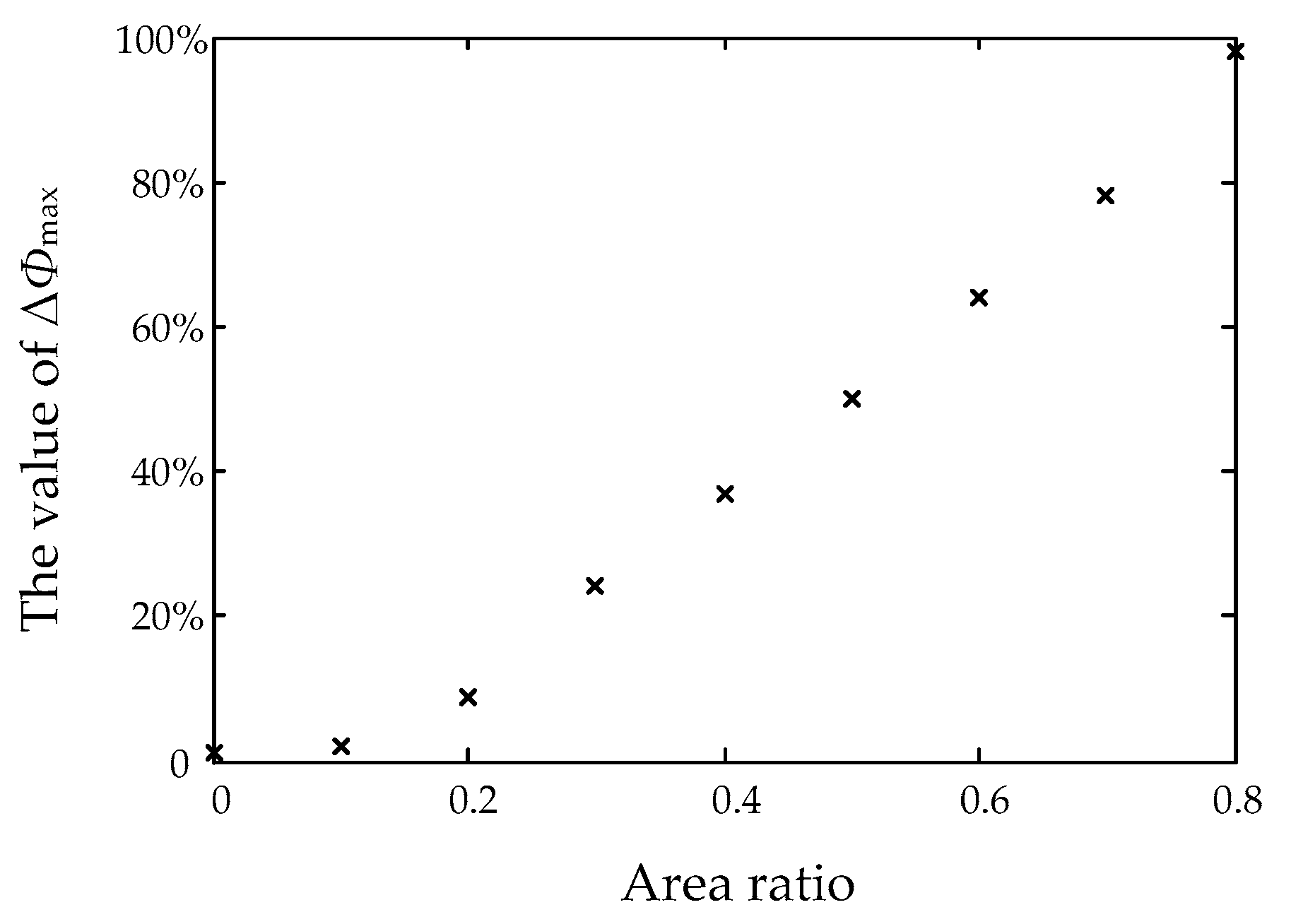
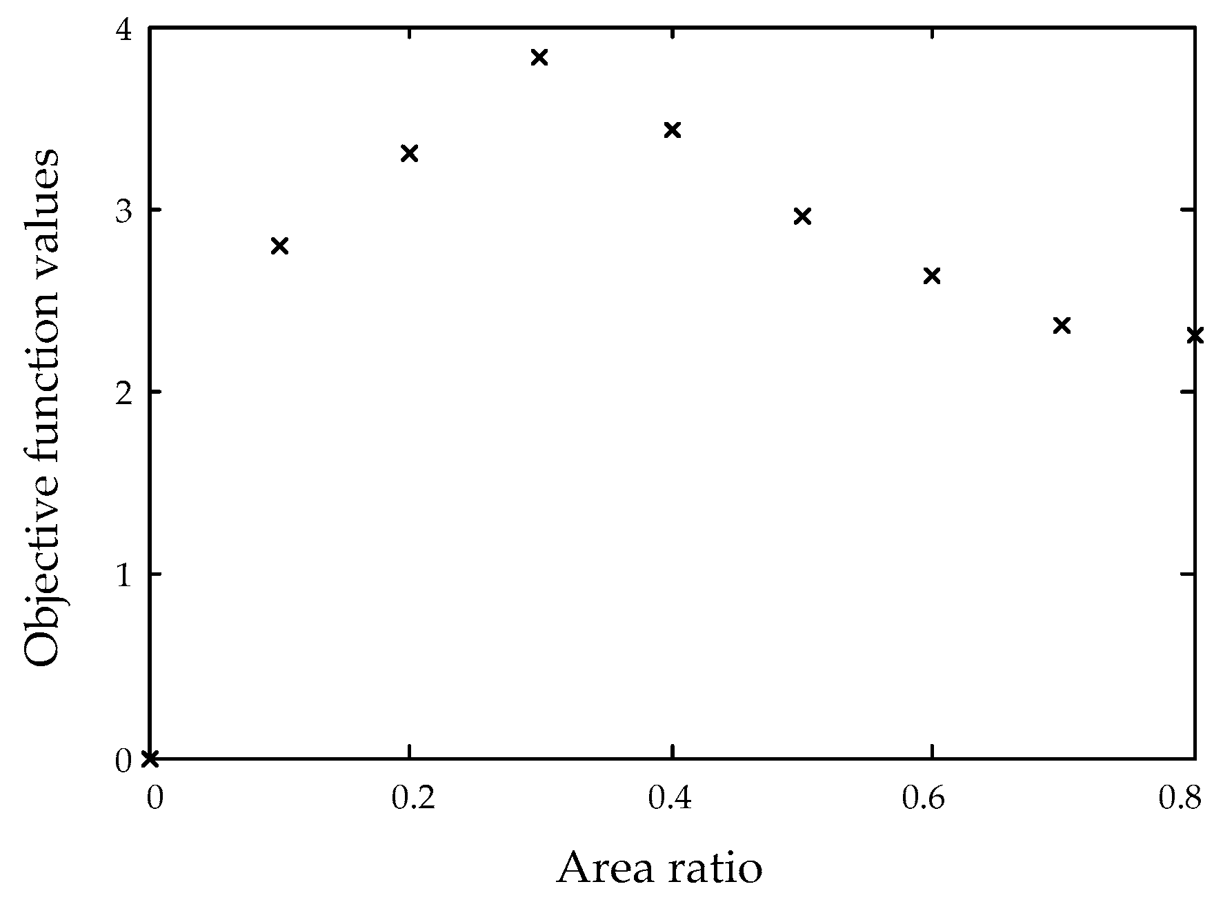
5.3. Optimum Area Ratio Value

In this section, the optimization for the optimum area ratio value of yokeless and segmented armature axial flux motor is carried out. According to the previous study, the field-weakening capacity can be enhanced with an incremented area ratio, but the back EMF and torque trend down. These optimization indexes contradict each other and make it impossible to obtain the optimal value simultaneously. Therefore, how to improve the performance of field-weakening without affecting the performance under base speed is identified as the principle of optimization. The specific optimization targets are as follows:
  • Sacrifice as few permanent magnets as possible to ensure magnet flux linkage.
  • Make the decrement of maximum torque as small as possible while keeping the current density constant at rated speed with an aim to ensure the constant power operation at high speed.
  • Make the variation of air gap flux as large as possible while giving same d-axis current with the purpose of improving the field-weakening performance.
Therefore, the objective function with constraint can be expressed as:
{ F obj = Δ Φ max Δ T em × δ 0 < δ 1
ΔΦmax and ΔTem are the key parameters in Equation (12). ΔΦmax is described in the previous section. And for a specific optimization model, ΔTem represents the percentage variation of rated torque relative to it of the original machine, it can be calculated by:
Δ T max = T em _ 0 T em T em _ 0
where Tem_0 is the rated torque as the area ratio is equal to zero. Both ΔΦmax and ΔTem are the function of area ratio, thus what the objective function needs to limit is the bound of area ratio δ.
The optimization target is achieved when the objective function reaches the maximum. The maximum value of the objective function indicates the largest changes of air gap flux and the lowest reduction of rated torque under per unit area ratio, which fully meets the optimization targets. This is a most cost efficient way to improve the performance of field-weakening. The ultimate purpose of optimization is to get the value of area ratio when the Fobj reaches maximum. The curve of the objective function values is shown in Figure 10.
Figure 10 can arrive at the conclusions that the peak value of objective function is obtained as the area ratio is equal to 0.3, and the promotion of the objective function value of other options is limited. When area ratio is equal to 0.1 or 0.2, the promotion field-weakening performance is less than 10%, which is of no value. When the area ratio is equal to 0.4, the value of objective function decreases by 10.5% and the promotion of field-weakening performance is nearly 50% in comparison with the optimal scheme, therefore, it is also a logical choice meeting the higher expectations of field-weakening performance. When the area ratio is equal to 0.5 or above, both the values of the objective function and the electromagnetic torque follow a trend of decline, thus, it is not recommended.
In summary, the optimum value of area ratio of yokeless and segmented armature axial flux motor is equal to 0.3. Under this optimum condition, the output amplitude of back EMF is nearly 94 V and maximum field-weakening effect is expected to reach about 24%. The optimized parameters of the new rotor are shown in Table 2.

6. Conclusions

This paper has investigated the design, analysis and optimization of a yokeless and segmented armature axial flux motor aiming to improve the field-weakening performance. It has been shown that replacing a part of the permanent magnetic materials by soft magnetic materials can effectively improve the field-weakening capacity of the machines. With this approach, a decrease of the air gap flux of the optimal model of over 24% can be achieved when the area ratio equals 0.3. The conclusions can be summarized as follows:
  • The results of our analytical calculation are quite consistent with results of the simulation, which proves the quite accuracy of the analytical calculation model and finite element simulation.
  • The existence of a soft magnetic part contributes to the decline of d-axis reluctance, therefore, a lower d-axis stator current is required while achieving the same demagnetizing effect of the machines. The air gap flux can be flexibly controlled while using an armature reaction as control mechanism.
  • It is effective to select the optimum area ratio so as to optimize the design of rotors by setting the rational objective function, weighing the improvement of field-weakening performance and impact on output performance caused by the permanent magnet reduction.

Acknowledgments

The research work described in this paper is supported by the National Natural Science Foundation of China (51577125).

Author Contributions

All the authors have contributed significantly. Xiaoyuan Wang conceived and designed the model; Sijia Xu performed the simulation; Sijia Xu and Chunpeng Li analyzed the data; Xiang Li made all graphics; Xiaoyuan Wang and Sijia Xu wrote the paper.

Conflicts of Interest

The authors declare no conflict of interest.

References

  1. Capponi, F.G.; Donato, D.G.; Caricchi, F. Recent advances in axial-flux permanent-magnet machine technology. IEEE Trans. Ind. Appl. 2012, 48, 2190–2205. [Google Scholar] [CrossRef]
  2. Parviainen, A.; Niemela, M.; Pyrhonen, J. Modeling of axial flux permanent-magnet machines. IEEE Trans. Ind. Appl. 2004, 40, 1333–1340. [Google Scholar] [CrossRef]
  3. Li, H.; Shen, J. FEA-based design and comparative study of axial flux permanent magnet machines with various topologies. Trans. Chin. Eletrotechnol. Soc. 2015, 30, 32–40. [Google Scholar]
  4. Zhou, T. Research on Axial Flux Permanent Magnet Fly Wheel Machine for Regenerative Braking in Electric Vehicle. Master’s Thesis, Southeast University, Naijing, China, 2015. [Google Scholar]
  5. Gonzalez-Lopez, D.A.; Tapia, J.A.; Wallace, R.; Valenzuela, A. Design and test of an axial flux permanent-magnet machine with field control capability. IEEE Trans. Magn. 2008, 44, 2168–2173. [Google Scholar] [CrossRef]
  6. Moncada, R.H.; Tapia, J.A.; Jahns, T.M. Analysis of negative-saliency permanent-magnet machines. IEEE Trans. Ind. Electron. 2010, 57, 122–127. [Google Scholar] [CrossRef]
  7. Mebarki, A.; Gerada, D.; Brown, N.L. Analysis of an axial PM flux machine with field weakening capability for engine integration. In Proceedings of the 7th IET International Conference on Power Electronics, Manchester, UK, 8–10 April 2014. [Google Scholar]
  8. Liu, X.P.; Chen, D.; Wang, M.; Huang, Y.F.; Xie, Q.H. Analysis of mechanical dynamics and flux weakening ability for a variable flux axial field permanent magnet electrical machine. Trans. Chin. Eletrotechnol. Soc. 2016, 31, 54–62. [Google Scholar]
  9. Chai, F.; Bi, Y.L. Research review of flux weakening methods of axial permanent magnet synchronous machine. Micromotors 2015, 48, 69–76. [Google Scholar]
  10. Zuo, S.G.; Wu, S.L.; Wu, X.D.; Shen, J.; Lin, F. Analytical model and optimization of torque of an axial flux permanent magnet synchronous motor. Trans. Chin. Eletrotechnol. Soc. 2016, 31, 46–53. [Google Scholar]
  11. Huang, Y.K.; Ge, B.Y.; Dong, J.N.; Lin, H.Y.; Zhu, J.G.; Guo, Y.G. 3-D analytical modeling of no-load magnetic field of ironless axial flux permanent magnet machine. IEEE Trans. Magn. 2012, 48, 2929–2932. [Google Scholar] [CrossRef]
  12. Ji, J.H.; Sun, Y.K.; Zhu, J.H.; Zhao, W.X. Design, analysis and experimental validation of a modular permanent-magnet machine. Trans. Chin. Eletrotechnol. Soc. 2015, 30, 243–252. [Google Scholar]
  13. Sung, S.Y.; Jeong, J.H.; Park, Y.S.; Choi, J.Y.; Jang, S.M. Improved analytical modeling of axial flux machine with a doublesided permanent magnet rotor and slotless stator based on an analytical method. IEEE Trans. Magn. 2012, 48, 2945–2948. [Google Scholar] [CrossRef]
  14. Zhang, B.Y.; Jia, Y.Q.; Feng, G.H. Novel permanent magnet synchronous machines with modules combination stator. Trans. Chin. Eletrotechnol. Soc. 2015, 30, 243–252. [Google Scholar]
  15. Kappatou, J.C.; Zalokostas, G.D.; Spyratos, D.A. 3-D FEM analysis, prototyping and tests of an axial flux permanent-magnet wind generator. Energies 2017, 10, 1269. [Google Scholar] [CrossRef]
  16. Woolmer, T.J.; McCulloch, M.D. Axial flux permanent magnet machines: A new topology for high performance applications. In Proceedings of the Hybrid Vehicle Conference, IET The Institution of Engineering and Technology, Coventry, UK, 12–13 December 2006. [Google Scholar]
Figure 1. Structure of yokeless and segmented armature axial flux motor: (a) Exploded view; (b) Side view.
Energies 10 01492 g001
Figure 2. Optimization of rotor: (a) Original rotor; (b) Optimized rotor.
Energies 10 01492 g002
Figure 3. Flux distribution of a rotor pole: (a) In no-load condition; (b) In demagnetization condition.
Energies 10 01492 g003
Figure 4. The distribution of no-load flux density of yokeless and segmented armature axial flux motor.
Energies 10 01492 g004
Figure 5. The curve of no-load flux density of yokeless and segmented armature axial flux motor.
Energies 10 01492 g005
Figure 6. The curve of back EMF effective value in no-load condition.
Energies 10 01492 g006
Figure 7. The curve of torque under rated-load conditions.
Energies 10 01492 g007
Figure 8. The curve of air gap flux under different d-axis current. The area ratio is 0.3.
Energies 10 01492 g008
Figure 9. The value of ΔΦmax under different area ratio.
Energies 10 01492 g009
Figure 10. The objective function values under different area ratio.
Energies 10 01492 g010
Table 1. The prototype parameters.
ParametersValue
Numbers of pole pairs5
Numbers of stator segment12
Numbers of phase3
Conductor diameter2.2 mm
Permanent magnet length8 mm
Back iron length10 mm
Airgap length1.5 mm
Active length81 mm
Inner diameter132 mm
Outer diameter204 mm
Table 2. The optimized parameters.
ParametersValue
Inner diameter of the soft magnetic part132 mm
Outer diameter of the soft magnetic part146.4 mm
Length of the soft magnetic part8 mm
Inner diameter of the permanent magnetic part146.4 mm
Outer diameter of the permanent magnetic part204 mm

