Abstract
Near-Zero-Energy Buildings are a challenge in terms of energy production, storage, consumption and management, but these technological solutions remain financially difficult to access in developing countries. To this end, a complete low-cost and reliable home energy-management prototype was first developed and implemented on a scale model. A PWM charge controller drove the flow of energy produced and consumed in order to ensure the optimization of both the consumption of energy and energy savings. Battery storage was also managed by the home automation module using a set of sensors. The prototype of the scale model incorporated complete energy management of all electrical devices with group priorities through a graphical interface in a real-time mode. After testing this system, the lighting management part was implemented in a large-scale smart solar home. A smart lighting system via a complete algorithm integrated on an Arduino Mega board was then realized and implemented in the life-size house. This first step focuses, above all, on the users’ comfort and, in particular, on the lighting management. The results show that this smart device thus makes it possible to achieve additional energy savings on an essential and yet already energy-efficient device: lighting.
1. Introduction
The building sector is one of the most energy-intensive and environmentally polluting; according to statistics, the building sector alone accounted for 39% of total CO2 emission through 36% of total global energy utilization in 2018 [1]. Therefore, it is one of the main targets for reducing final energy consumption. The energy consumption of a building represents up to 40% of total energy consumption, especially in developed countries [2,3].
During the last decade, the concept of Zero-Energy Buildings (ZEB) and/or near-Zero-Energy Buildings (n-ZEB) has emerged. This notion, introduced to limit energy consumption and polluting emissions from buildings, is defined as being a building which annually generates at least as much energy as it consumes [4,5].
In order to stimulate the energy transition of the construction sector, European energy policies introduced the n-ZEB objectives (Directive, 2010/31/EU and 2018/844/UE) [6]. Similar measures were implemented in the USA as mentioned in the planned program activities in 2008 [7].
As part of the European Green Deal, with the European Climate Law, the EU has defined a target of achieving climate neutrality by 2050. This requires current greenhouse gas emission levels to drop substantially in the next decades. As an intermediate step towards climate neutrality, the EU has raised its 2030 climate ambition, committing to cutting emissions by at least 55% by 2030.
To achieve this performance level (n-ZEB) for a building or dwelling, three main steps must be taken: using energy-efficient construction strategies, adopting high energy-efficiency end-use technologies and using Renewable Energy (RE) production systems [8,9,10]. To increase the energy efficiency of a house, in addition to high-energy efficiency appliances and low-consumption lighting, efficient energy management in the building or home is imperative.
The challenge resides in implementing an appropriate energy management strategy that permits matching the intermittent Renewable Energy (RE) production with the dynamic power demand [11] while insuring user comfort.
There are several interesting works on the study of structures, components and benefits of photovoltaic (PV) energy resources [8]. Considering their application in the residential sector, these works focus on finding the compromise between residential consumption profiles and the electricity generated by PV systems. This solution is based on Home Energy Management (HEM) algorithms to reduce consumption and allow autonomous operation of the home.
In order to improve HEM systems, several algorithms have been developed [12,13,14]. Some of them are based on demand response (DR), in which the priority of use of diverse loads is taken into consideration [15]. Other algorithms are based on optimization methods in the management of domestic loads in order to decrease the consumer’s electricity bill by minimizing consumption and ensuring user comfort [11]. These methods can help users to use appliances in an optimal way according to several feed-in tariffs and comfort settings [11].
At the Solar Equipment Development Unit (UDES), a project named ‘Smart Solar Home’ has been launched as a demonstrator to show how far home energy demand could be satisfied by local photovoltaic production. Different aspects have been taken into account in order to lower the energy needs of the house, such as using appropriate materials to improve the thermal insulation of the house and the most energy-efficient appliances. Furthermore, to reach the energy balance between the production and the consumption, a Home Energy Management system (HEM) which both controls the energy flows and manages the load was developed.
In this paper, the case of the UDES demonstrator on a reduced scale (1/10) was treated. It is powered by a grid–connected photovoltaic plant with energy storage. With the aim of reducing energy consumption and ultimately achieving self-sufficiency in the house, an energy flow control system through a developed algorithm is used, integrating a combination of switches to ensure the optimal energy management between the energy produced by the PV system, the batteries’ storage and/or the energy from the grid.
The energy flow management and control system are composed of a PWM charge controller for the battery and a load management system consisting of several switches and loads which are controlled by the microcontroller according to their priority. The microcontroller programming is set in such a way that it could control all the hardware of the PWM module, read the various data received and finally send the latter to the user as needed.
To optimally use the available energy produced locally, a Home Automation System equipped with several sensors (temperature, humidity, motion, presence, etc.) was set up. The control system and the HEM were either connected remotely to a Graphical Interface, which sets the communication between the system and the user, or in a local network mode. Orders may be entered and data displayed on any electronic device (mobile phone, digital tablet, etc.) with a web browser.
Many home automation systems already exist, but their cost remains unaffordable for most developing countries. The main contribution of this study is the development of a complete energy management system that is robust, reliable and, above all, inexpensive, integrating safety, air quality, interior lighting and comfort. The complete system has been successfully tested on a small scale. The implementation of lighting management applied to a real case demonstrated that it was possible to obtain additional energy savings while ensuring user comfort. This constitutes an innovative low-cost development that is accessible to developing countries [16,17].
2. Materials and Methods
Initially, the HEMS management device was fully produced, programmed and applied to a 1:10 scale model of the real building. After a testing campaign of several months on the model, lighting management was implemented in real conditions on a 57 m2 building with a 22° inclined roof equipped with photovoltaic panels with an area of 18 m2.
The house was made with special materials that were carefully chosen to have good thermal insulation. The interior cladding is made of flat polyurethane plates and the exterior cladding is made of wooden panels. The openings of the house are in PVC double glazing equipped with white blinds which open and close automatically. The household appliances were selected on the basis of energy efficiency criteria. The house is equipped with 10 LED tubes of 16 W each, as well as 7 LED spotlights of 18 W each. The total lighting consumption is 1.55 kWh in one day period.
The results presented for the lighting are an average of energy consumption carried out over more than ten tests following the same protocol with the blinds closed, decorrelated from the influence of temperature, climate, or season, with and without management.
The following paragraphs describe more precisely each of the modules of the device produced and applied.
2.1. Home Energy Management System
To fulfill the energy needs of the house by photovoltaic production as much as possible, a Home Energy Management System (HEMS) was developed. This system is shown in Figure 1. It consists of:
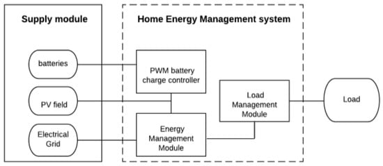
Figure 1.
Interaction links between power supply and load via the HEM System.
- A Supply Module (PV field, batteries and AC electrical grid network).
- An Energy Management Module, which, depending on the available energy, facilitates meeting the energy demand of the dwelling by optimally managing the energy flow according to an appropriate strategy.
- A Load Management Module, which manages the distribution of the loads according to a defined priority to save energy and ensure comfort for the user.
- A Pulse Width Modulation (PWM) charge controller, which controls the charging and discharging of the battery bank to avoid its overloading and deep discharge, thus ensuring its longevity.
The operation of the HEMS is based on the following priority rules. The electricity produced by the PV panels must supply the loads. If there is an excess of production, it will charge the batteries, and then the surplus of energy will be injected to the grid. The aim is to simultaneously increase the energy self-sufficiency of the residential buildings and decrease the energy withdrawn from the grid.
2.1.1. PWM Battery Charge Controller
The Arduino board is the principal element of the management system; it calculates all the elements necessary for the good functioning of the management system in addition to allowing a complete visualization of the information in real time. The diagram in Figure 2 presents the PWM charge controller of the energy management system.
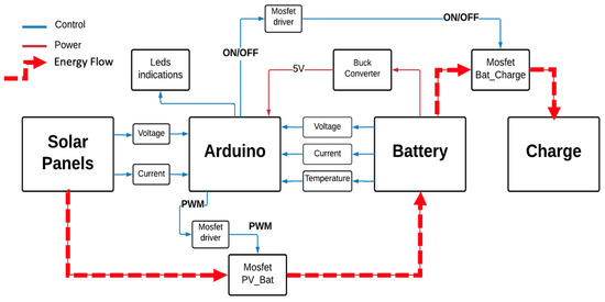
Figure 2.
PWM battery charge controller with control/power command connections and energy flow.
The PWM technique is characterized by the presence of a switching element between the photovoltaic panels and the battery; this element is opened and closed by a PWM ‘Pulse Width Modulation’ control signal of constant frequency and variable duty cycle. This control technique chops the current generated by the photovoltaic panels into pulses in order to regulate the amount of charge in the battery. If the battery voltage increases, the pulse width decreases and the charging current also decreases. The Arduino is powered from the battery via a Buck voltage converter (step-down). It transforms an incoming voltage into a lower output voltage. The voltage divider is used to reduce the voltage of the PV panel and the battery below 5 V once at the analog pin to be supported by Arduino. The current measured at the PV panels and the battery is useful for calculating the power and energy produced and consumed by the PV modules and the loads, respectively, in real time. In this study, a MOSFET transistor (Metal Oxide Semiconductor Field-Effect Transistor) was used as a switch because the bipolar transistor has a higher loss and the relay has a low switching time. A MOSFET driver was also used to allow the microcontroller to produce a low-current digital output signal to drive the MOSFET gate. For the display, 4 LEDs for system status indication have been implemented; a red LED indicating that the battery is discharged, an orange LED indicating that the solar panel is disconnected, a blue LED indicating that the battery is charging and a green LED indicating that the battery is fully charged.
Figure 3 shows the flowchart for the battery management using the PWM technique implemented in the Arduino card. This algorithm has the battery voltage and the PV panels voltage in real time as inputs. The battery charge will depend mainly on its State of Charge (SoC). A maximum charging would imply a PWM duty cycle equal to zero and therefore no load. On the other hand, if the battery is not at its maximum, the duty cycle of the PWM load will be determined as a function of the voltage with respect to the fast load and hold load thresholds.
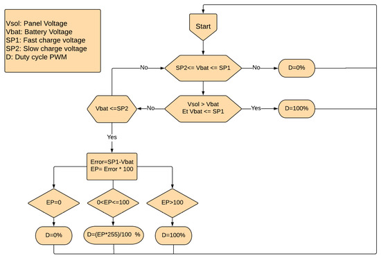
Figure 3.
PWM algorithm.
2.1.2. Energy Flow Management Strategy
The energy demand of the house is satisfied using the energy produced locally through the PV system, managed with the energy flow algorithm. As shown in Figure 4, the flowchart of this algorithm presents the energy management strategy, which consists of using the photovoltaic energy as much as possible to achieve self-consumption. The elaborated algorithm is based, essentially, on three inputs; the PV energy production, the State of Charge (SoC) of the battery and the energy demand. The state of these three inputs leads the choice of the adopted operating modes, as mentioned in Table 1. Potential instabilities due to decision boundaries are managed by a programmed flip-flop and applied in all similar cases.
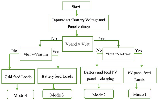
Figure 4.
Flowchart of the Energy Management Strategy.

Table 1.
Energy Flow Management Operating Modes.
2.1.3. Load Energy Management
Sometimes, even if locally produced energy is available, it may not be enough to meet the entire energy demand of the home. This is why an order of priority between charges is pre-established and its implementation is ensured thanks to the Load Energy Management System (LEMS), which principally consists of four inputs: the PV; the power produced, Pp; the power stored, Ps, depending on the SoC; and the consumed power, Pc. According to the parameters, the LEMS will decide which appliances will be fed based on predefined priorities to ensure user comfort. The LEMS is based on the automatic control of the operation of the household electrical appliances, divided into 3 groups according to their priority (Table 2):
Table 2.
Priorities of use of the home appliances.
- Group 1 (priority 1): Important devices in the house that must always be plugged in and cannot be disconnected (refrigerator, Wi-Fi, TV, computer, lamps).
- Group 2 (priority 2): Devices that can be unplugged (or delayed) (dishwasher, space heater, washing machine, water heater, air conditioner).
- Group 3 (priority 3): Devices that can be used only when there is enough photovoltaic production or the batteries are charged in order to avoid the use of the grid (iron, vacuum).
For given data of the produced energy and the consumed energy, as well as the State of Charge of the battery at time t, the system supplies appliances according to their priority of use [15]. These load groups are active and available according to the modes established during the energy flow management as shown in Table 3.
Table 3.
Load Energy Management.
As can be seen in Table 3, Group 1 is still active because it is the highest priority group, ensuring the minimum comfort that user must have. In Mode 4, where the grid comes into play while the battery is in critical condition, the only active group is the highest priority, in order to make the maximum possible energy saving.
2.2. Home Automation
The Home Automation System is a system that controls lighting, space conditioning, entertainment systems and appliances. It may also include home security, such as access control and alarm systems.
The functions of the automation system are:
- Remote access: the user of the system, once identified, will be able to access the system from the internet.
- Automatic management of the smart home appliances thanks to sensors, using a local network or the internet.
- Visualization of the metrics and the states, using either the internet or a local network to consult the values transmitted by the various sensors (humidity, gas, water level and temperature) and the states of each actuator.
- Visualization and monitoring of the electricity production and consumption, the State of Charge of the battery as well as other functionalities, using the internet or a local network.
- Add sensors and actuators: the system administrator can extend the functionality of the house with new sensors and actuators.
2.2.1. Design of Home Energy Management System and Home Automation System
This section shows the different design stages of the device with the different cases discussed in the operating principles in the above sections. Tests were carried out on test prototypes each having a specific task:
- The first test prototype performs PWM regulation of the battery charge that can be seen in Figure 5a, and, in addition, it contains some sensors of the home automation system that will subsequently be arranged separately.
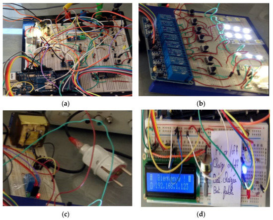 Figure 5. Different parts of the prototype where (a) PWM charge controller, (b) the divided loads in three groups, (c) a relay and an AC–DC converter, (d) LCD display mainly containing the IP address which allows the users to access the graphical interface.
 - The second test prototype has the role of managing the different electrical loads of the solar house according to the priorities. These loads are arranged in three groups as discussed before (Figure 5b).
- The third prototype contains a relay and an AC–DC converter allowing the system to help the network in case of extreme need (adverse weather conditions and depletion of the battery charge) (Figure 5c).
- The last prototype deals with the LCD display, mainly containing the IP address that will allow the user of the house to access the graphical interface and its various services. The LED display is used to indicate the battery charge level and the connection status of the solar panel with the system (Figure 5d).
It should be noted that the Arduino Mega 2560 board not only controls the energy flow and load management system, but is also the main element managing all the integrated actuators and sensors. Sensors send the data to the Arduino, which will transmit them to the Ethernet Shield to visualize in a local network or via the internet, and subsequently to control the loads via actuators (Figure 6 and Figure 7).
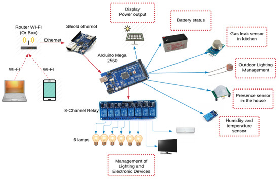
Figure 6.
Home Automation System.
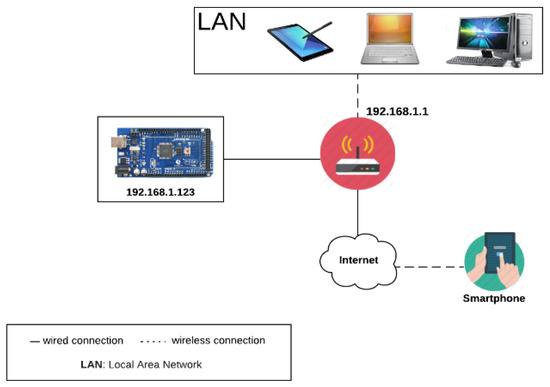
Figure 7.
Description of Network architecture.
For an 8-channel relay module, this is a relay interface board, which can be controlled directly by a wide range of microcontrollers. It is also able to control various devices and equipment with a large current. The relay module is widely used for any MCU control, industrial sector, PLC control, or intelligent home control. In this case, an 8-channel relay module is chosen in order to control:
- Lighting of 4 different rooms
- Air conditioning and television
- Lighting controlled by the Passive Infra-Red (PIR) presence sensor
- Lighting controlled by the Light-Dependent Resistor (LDR) sensor
The Arduino is not made to use a network link, such as Ethernet, because there are several protocols to respect. This is why the card will be supported by a Shield called “Shield Ethernet” which will allow us to connect to a local network or the internet. This Shield will therefore allow the Arduino to be unloaded from all network layers processing to give only information useful to the network.
This graphical user interface (GUI) is accessible from any device with an internet connection and a web browser. Figure 8 shows the display page of different data at different meteorological conditions, thus, different energies produced and consumed, the battery (its state and the type of charge), as well as data provided by the sensors, such as temperature, humidity or gas.
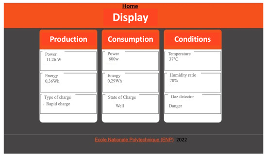
Figure 8.
Interface Display.
The remote control of the image loads page is operational and allows the user total control over lighting and the most relevant electrical devices, thus achieving a potential energy saving as well as optimization of comfort.
2.2.2. Realization of the Model and Its Components
Figure 9 shows the different stages of the design of the house model and its components. After making the right sizing of the whole 1:10 scale prototype according to the dimensions of the UDES solar house, the scale model was designed with many details for a more realistic appearance. The sizing of the different loads followed the previous scale. Electrical loads were modeled in DC lighting for scaling (0.1 watts for the lowest and 3.5 watts for the largest). As for the solar panels, they are placed at the level of the roof at an angle of approximately 36 degrees. This established prototyping allowed us to create an almost exact replica of the solar home of the UDES on a reduced scale.
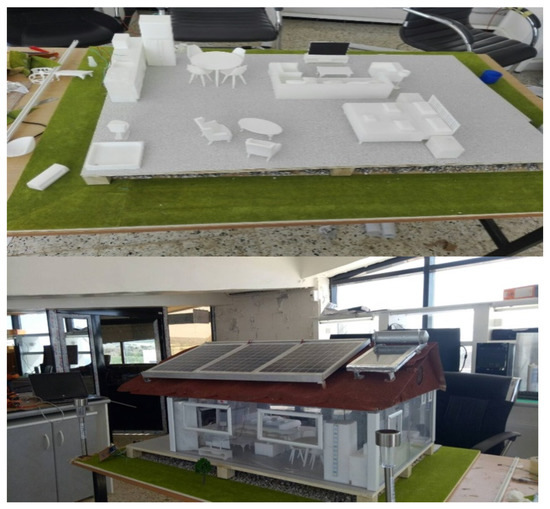
Figure 9.
Realization of the model of the solar house.
2.2.3. Integration of the Circuit in the Model
The implementation of the energy management system as well as the home automation system to the prototype of the solar home on a reduced scale was correctly carried out (Figure 10). The prototype being inside and the solar panels outside (Figure 11), the PV power produced remained sufficient to feed all the loads arranged (to the extent of a realistic scenario), proving the reliability of the system.
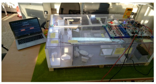
Figure 10.
Implementation of the system in the prototype of the solar house on a small scale.
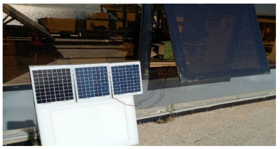
Figure 11.
Photovoltaic panels.
Having been carried out on the realized model, this set of tests allowed us to see the different performances of the management of energy flows and loads in the house. The energy management system makes it possible to operate the appliances of the prototype in an optimal way, ensuring energy saving and user comfort. The management of the loads is, however, not visible, because the system deals with them automatically. Figure 12 illustrates the result of the realized scaled-down prototype.
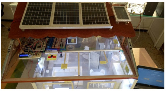
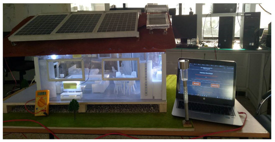
Figure 12.
Final result of the scaled-down prototype.
2.3. Solar Home Model Description
The installed dwelling of this case study is located in the town of Bou–Ismaïl (Latitude: 36°38′33.43″ North; Longitude: 2°41′24.25″ East), in Algeria, and its area is 57 m2. The PV installation used to feed the house is calculated using “PVsyst” software [18] based on real temperature and irradiation data of the Bou-Ismail site, the one-day autonomy and the predefined load profile of the home. This house is powered with a photovoltaic system of 3.2 kWp capacity, 12 kWh of Plomb-acid battery storage capacity and a 4 kW grid-connected inverter [19,20]. Figure 13 describes the PV-grid system with backup installed in UDES’ solar house.
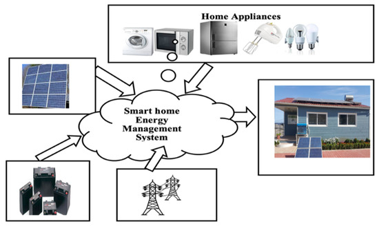
Figure 13.
Description of the PV-grid system with backup installed in UDES’ solar house.
2.4. Smart Lighting Control System in UDES’ Solar Smart House
Inhabitants have the bad habit of leaving the lights turned on even when it is not necessary, for example, when it is bright enough outside and when someone forgets to turn the lights off when leaving. This results in a non-negligible waste of energy. The introduction of the smart lighting control system in UDES’ solar smart house only allows the lights to be turned on when needed, avoiding any energy waste due to lighting. The aim of this installation is to reduce the energy consumption of the house. The circuit will be shown and the algorithm of the system management will be explained. The aim of this installation is to lower the energy consumption of UDES’ solar smart house using smart automation. The block diagram presented in Figure 14 describes the working principle of the proposed lighting control system. Components presented in Figure 14 are described as follows.
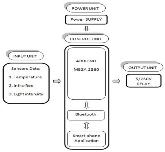
Figure 14.
Block diagram of the proposed lighting control system [21].
2.4.1. Input Unit
This unit contains sensors and detectors that provide an input signal (analog or digital) to the Arduino microcontroller. The exact and optimal position of each sensor was found after several tests carried out on the surface, taking into consideration the amplitude limits and characteristics of each device. Figure 15 shows the position of each sensor that represents the input unit of the installation in the solar smart house.
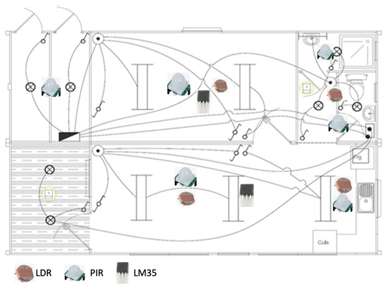
Figure 15.
Electrical installation and sensors’ position (LDR, light sensor, PIR, movement sensor and LM35 temperature sensor) in UDES’ solar smart house.
Sensors were connected to the control circuit through network cables that are thin and suitable for low currents, and one cable can hold up to 8 wires, which minimizes the cost of cables. Since the PIR needs 3 wires, the LDR 2 wires and the temperature sensor (LM35) 3 wires, just 1 network cable can be used for all these sensors in a desired location.
2.4.2. Smart Control
In the smart control, data are collected automatically from the sensors installed and displayed on the serial monitor interface of Arduino. They are then compared with fixed values in the program, for example, light intensity in lux for each zone of the house as mentioned in Section 3.2. The motion state is also taken into consideration when comparing data. Finally, relays are triggered when all conditions are satisfied; motion is detected and light intensity in lux is less than the needed value. This smart control provides real-time control of the lighting system in the house. The algorithm in Figure 16 summarizes the working principle of the proposed smart lighting control system.
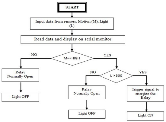
Figure 16.
Lighting system smart control algorithm [21].
2.4.3. Output Unit
The Output Unit gathers two main components: relays and luminaires. When motion is detected in a zone of the house, the relay connected to the luminaire of that zone is energized. As a result, the light turns on. This is shown in Figure 17.
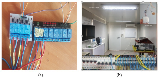
Figure 17.
Implementation of the proposed automatic lighting control in solar house: (a) relays and (b) luminaires turned on when the conditions are satisfied.
3. Results and Discussion
3.1. Smart Lighting Control System Implementation
Smart lighting control provides real-time control; thus, the energy is used only when needed. The overall smart lighting control circuit developed in this work is tested in summer conditions for 24 h. Lights are turned on for a smaller time period compared with the non-controlled lights. The lighting usage time is reduced from 10 h/day to 8.25 h/day, which represents 11.66% of time gain. Experimental results are explained in Table 4.
Table 4.
Lighting energy consumption of UDES’ solar smart house with and without smart control.
- As a result, the total lighting energy consumption by using smart control is about 1.30 kWh instead of 1.55 kWh calculated without any control. It represents a 15.88% optimization of lighting energy consumption (Figure 18).
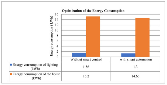 Figure 18. Graph summarizing the values of energy consumption of the lighting and the house.
 - The total energy consumption in the house using smart lighting control system is about 12.99 kWh instead of 13.25 kWh calculated without control. It represents a 2% decrease in the energy consumption compared with the classical lighting system of UDES’ solar smart house.
The implementation of the lighting part and its management shows a drop in energy consumption. These measurements were carried out without any particular scenario and without thermal management (blinds closed). Thermal management is another control module. Between the two, the management of the opening of the blinds will simultaneously influence the temperature and the lighting. It is obvious that, regarding lighting, we will obtain increased savings. Modulating the opening of the awning will always provide energy savings on lighting as well as savings on heating. This last element consuming more energy than the lighting, the opening of the blinds is prioritized over the temperature parameter, always having a positive effect on the lighting.
3.2. Comparative Study of Smart Lighting Indoor Management
For Zero-Energy or n-ZEB Buildings, as well as for indoor smart lighting applications, different technologies have been developed for data processing and detection [22]. Table 5 lists some of these examples according to the technology used, the energy saving achieved and a relative estimate of the installation cost.
Table 5.
Comparative study of smart lighting technologies, energy saving and cost evaluation.
In general, smart lighting devices require a substantial investment both for the installation of sensors and for data processing. Nevertheless, the energy savings achieved can exceed 50%, which makes these devices interesting from a long-term economic point of view. Nevertheless, although the return on investment is guaranteed, the initial material investment remains a brake on the development of these technologies, particularly in developing countries. The results we have obtained are not the highest to be found in the literature, but the system put in place makes it possible to complete the range of technological proposals with a financially accessible low-cost system.
4. Conclusions
The objective in this study is to create a financially accessible smart home system in developing countries by exploiting low-cost Arduino open-hardware technology. This system can be managed and controlled remotely in real time (via a web interface). It can also be extended by actuators and sensors that the administrator can add and configure according to their needs, in addition to being able to monitor the energy consumption of the house. The goal is to provide comfort to the user and to provide energy saving with a smart inexpensive system.
This article presents the different stages of the implementation of the device, from the study and the concept to the production of a model aimed at raising public authorities’ awareness of the need to deploy this type of device. A model was made with its various components, as well as the energy management system and the design of the graphical user interface, which constitute the essentials of the home automation system, and finally these last two were integrated into the prototype of the solar house on a reduced scale.
After this preliminary phase, an energy management system was developed in a real building with 57 m2 surface. An Arduino Mega-based smart lighting control system was designed and implemented in the house. Using this circuit, the energy consumption was reduced. In addition, the circuit ensured adaptability and reliability to make the house more comfortable for inhabitants and consume much less energy. This study proved the feasibility of integrating an economical energy management device based on an Arduino module. In addition, a smart lighting-control system can reduce the energy consumption of the house by reducing the time lights are on. It results in a reduction of 15.88% in the lighting energy consumption and a reduction of 2% in the total energy consumption in the house. Remote control can optimize the contribution of solar energy production and also avoid some energy losses due to home appliances turned off or paused but still plugged in.
One of the objectives of the study is to make the tools for saving energy economically accessible. Indeed, we are facing a paradox that only rich countries have the means to invest in order to save money and become even richer.
The link between energy and poverty is obvious. Giving access to energy means reducing mortality, developing education and economic development. Reducing and optimizing energy consumption is a small link in this chain and making these energy management devices economically accessible is a way of contributing to it. According to international criteria, Algeria is part of this list of developing countries. This study developed at the UDES Research Unit is, therefore, perfectly aware of the economic reality, the cost of the products available on the market and the equipment potentially accessible for developing countries to build n-ZEBs.
In summary, this work has contributed to:
- offering a reliable and low-cost solution necessary for developing countries with strong sunlight which are favorable areas for the development of solar energy, including in the residential sector, which is an essential asset for the development of Zero-Energy-Buildings (ZEB)
- improving intelligent lighting control to reduce energy consumption.
- improving the comfort of residents through remote control solutions and helping optimize the energy consumption of household appliances.
The good results presented in this study make it possible to reflect on the generalization of the concept of solar smart houses in sunny developing countries. Future work will focus on controlling household appliances using smart plugs and will use smart, low-power and fully controllable devices.
Author Contributions
Conceptualization, methodology, software, validation, F.C., O.T. and Z.M.K.; writing—original draft preparation, F.C.; writing—review and editing, A.T.d.A., A.T. and L.C.; project administration, F.C.; funding acquisition, F.C. and L.C. All authors have read and agreed to the published version of the manuscript.
Funding
This research was funded by the Directorate General for Scientific Research and Technological Development DGRST/Ministry of Higher Education & Scientific Research (Algiers), MESRS under contract N° 185 DGRSDT -UDES/CDER. This is also part of the PHC “Maghreb” (Program Hubert Curien) MELINA (Mastering Efficient Lighting in North Africa) granted to L.C. and funded via Campus France (Grant number 43981ZG) by the French Ministry of Europe and Foreign Affairs and the Algerian Ministry of Higher Education and Scientific Research.
Acknowledgments
The authors would like to thank Mahrane Achour, Director of Research at UDES, as well as the entire team that participated in the construction of the smart solar home.
Conflicts of Interest
The authors declare no conflict of interest. The funders had no role in the design of the study; in the collection, analyses, or interpretation of data; in the writing of the manuscript; or in the decision to publish the results.
Nomenclature
| PV: Photovoltaic |
| SoC: State of Charge |
| RE: Renewable Energy |
| D: Duty cycle |
| Pp: Power produced |
| Ps: Power stored |
| Pc: Power consumed |
| LAN: Local Area Network |
| GUI: Graphical User Interface |
| PWM: Pulse Width Modulation |
| MOSFET: Metal Oxide Semiconductor Field-Effect Transistor |
| HEM: Home Energy Management |
| HEMS: Home Energy Management System |
| LEMS: Load Energy Management System |
| n-ZEB: near-Zero-Energy Building |
| MCU: Micro Controller Unit |
| PIR sensor: Passive InfraRed sensor |
| LDR sensor: Light-Dependent Resistor sensor |
| PLC: Programmable Logic Controller |
References
- IEA. 2019 Global Status Report for Buildings and Construction; IEA: Paris, France, 2019; Available online: https://www.iea.org/reports/global-status-report-for-buildings-and-construction-2019 (accessed on 1 December 2020).
- Abdelghani, H.; Yahya, L.; Ahmed, A. Energy Optimization and Management in a Building Using Clean Energy. WSEAS Trans. Syst. 2021, 16, 61–66. [Google Scholar] [CrossRef]
- Saini, L.; Meena, C.S.; Raj, B.P.; Agarwal, N.; Kumar, A. Net Zero Energy Consumption building in India: An overview and initiative toward sustainable future. Int. J. Green Energy 2022, 19, 544–561. [Google Scholar] [CrossRef]
- Sartori, I.; Napolitano, A.; Voss, K. Net zero energy buildings: A consistent definition framework. Energy Build. 2012, 48, 220–232. [Google Scholar] [CrossRef]
- Vieira, F.M.; Moura, P.S.; de Almeida, A.T. Energy storage system for self-consumption of photovoltaic energy in residential zero energy buildings. Renew. Energy 2017, 103, 308–320. [Google Scholar] [CrossRef]
- EUR-Lex. Directive 2010/31/EU of the European Parliament and of the Council of 19 May 2010 on the Energy Performance of Buildings. Available online: https://eur-lex.europa.eu/LexUriServ/LexUriServ.do?uri=OJ:L:2010:153:0013:0035:en:PDF (accessed on 27 November 2022).
- Energy, R. Building Technologies Program. Res. Dev. 2008, 2, 1. [Google Scholar]
- Harkouss, F. Optimal Design of Net Zero Energy Buildings under Different Climates. Ph.D. Thesis, Université Côte d’Azur, Nice, France, 2018. [Google Scholar]
- Meena, C.; Raj, B.; Saini, L.; Agarwal, N.; Ghosh, A. Performance Optimization of Solar-Assisted Heat Pump System for Water Heating Applications. Energies 2021, 14, 3534. [Google Scholar] [CrossRef]
- Alam, T.; Meena, C.; Balam, N.; Kumar, A.; Cozzolino, R. Thermo-Hydraulic Performance Characteristics and Optimization of Protrusion Rib Roughness in Solar Air Heater. Energies 2021, 14, 3159. [Google Scholar] [CrossRef]
- Althaher, S.; Mancarella, P.; Mutale, J. Automated Demand Response from Home Energy Management System under Dynamic Pricing and Power and Comfort Constraints. IEEE Trans. Smart Grid 2015, 6, 1874–1883. [Google Scholar] [CrossRef]
- Pau, G.; Collotta, M.; Ruano, A.; Qin, J. Smart home energy management. Energies 2017, 10, 382. [Google Scholar] [CrossRef]
- Tascikaraoglu, A.; Boynuegri, A.; Uzunoglu, M. A demand side management strategy based on forecasting of residential renewable sources: A smart home system in Turkey. Energy Build. 2014, 80, 309–320. [Google Scholar] [CrossRef]
- Abdelhamid, N.M.; Lejdel, B.; Clementini, E. Optimizing of Consumption Energy in Smart Building. WSEAS Trans. Syst. Control 2022, 17, 428–438. [Google Scholar] [CrossRef]
- Drir, N.; Chekired, F.; Rekioua, D. An integrated neural network for the dynamic domestic energy management of a solar house. Int. Trans. Electr. Energy Syst. 2021, 31, e13227. [Google Scholar] [CrossRef]
- Bouroussis, C.; Topalis, F.V. Smart multi-workplane lighting control and utilization of daylight using an imaging photosensor. In Proceedings of the 16th IEEE International Conference on Environment and Electrical Engineering, Florence, Italy, 7–10 June 2016. [Google Scholar] [CrossRef]
- Adam, G.K.; Kontaxis, P.A.; Doulos, L.T.; Madias, E.-N.D.; Bouroussis, C.A.; Topalis, F.V. Embedded Microcontroller with a CCD Camera as a Digital Lighting Control System. Electronics 2019, 8, 33. [Google Scholar] [CrossRef]
- Chikh, M.; Mahrane, A.; Bouachri, F. PVSST 1.0 sizing and simulation tool for PV systems. Energy Procedia 2011, 6, 75–84. [Google Scholar] [CrossRef]
- Chekired, F.; Houtti, S.; Bouroussis, C.A.; Rahmani, A.; Tilmatine, A.; Canale, L. Low Cost Automation System for Smart Houses based on PIC Microcontrollers. In Proceedings of the 2020 IEEE International Conference on Environment and Electrical Engineering and 2020 IEEE Industrial and Commercial Power Systems Europe (EEEIC/I&CPS Europe), Madrid, Spain, 9–12 June 2020; pp. 1–5. [Google Scholar] [CrossRef]
- Chekired, F.; Smara, Z.; Mahrane, A.; Chikh, M.; Berkane, S. An Energy Flow Management Algorithm for a Photovoltaic Solar Home. Energy Procedia 2017, 111, 934–943. [Google Scholar] [CrossRef]
- Chekired, F.; Canale, L.; Tadjer, S.; Louni, A.; Bouroussis, C.A.; Tilmatine, A. Low Cost House Automation System based on Arduino Microcontroller. In Proceedings of the 2021 IEEE Industry Applications Society Annual Meeting (IAS), Vancouver, BC, Canada, 10–14 October 2021. [Google Scholar] [CrossRef]
- Soheilian, M.; Fischl, G.; Aries, M. Smart Lighting Application for Energy Saving and User Well-Being in the Residential Environment. Sustainability 2021, 13, 6198. [Google Scholar] [CrossRef]
- Byun, J.; Hong, I.; Lee, B.; Park, S. Intelligent household LED lighting system considering energy efficiency and user satisfaction. IEEE Trans. Consum. Electron. 2013, 59, 70–76. [Google Scholar] [CrossRef]
- Ahmadi-Karvigh, S.; Ghahramani, A.; Becerik-Gerber, B.; Soibelman, L. Real-time activity recognition for energy efficiency in buildings. Appl. Energy 2018, 211, 146–160. [Google Scholar] [CrossRef]
- Tang, S.; Kalavally, V.; Ng, K.Y.; Parkkinen, J. Development of a prototype smart home intelligent lighting control architecture using sensors onboard a mobile computing system. Energy Build. 2017, 138, 368–376. [Google Scholar] [CrossRef]
- Ringel, M.; Laidi, R.; Djenouri, D. Multiple Benefits through Smart Home Energy Management Solutions—A Simulation-Based Case Study of a Single-Family-House in Algeria and Germany. Energies 2019, 12, 1537. [Google Scholar] [CrossRef]
- Cimini, G.; Freddi, A.; Ippoliti, G.; Monteriù, A.; Pirro, M. A Smart Lighting System for Visual Comfort and Energy Savings in Industrial and Domestic Use. Electr. Power Compon. Syst. 2015, 43, 1696–1706. [Google Scholar] [CrossRef]
- Kwon, S.-Y.; Lim, J.-H. Multi-objective context-adaptive natural lighting system. Energy Build. 2017, 144, 61–73. [Google Scholar] [CrossRef]


Publisher’s Note: MDPI stays neutral with regard to jurisdictional claims in published maps and institutional affiliations. |
© 2022 by the authors. Licensee MDPI, Basel, Switzerland. This article is an open access article distributed under the terms and conditions of the Creative Commons Attribution (CC BY) license (https://creativecommons.org/licenses/by/4.0/).