Featured Application
Carbonate films grown by green chemistry on magnesium have a high potential to be used as a non-toxic protective barrier with possible application in biodegradable implants.
Abstract
Mg is one of the few materials of choice for biodegradable implants, despite its rapid degradation when used without surface protection treatment. This study presents the effect of carbonation time on the formation of hydrophobic carbonate coatings grown on pure magnesium using a simple, green chemical conversion method in carbonated water. The evolution of the coating with immersion time in carbonating solution was studied in order to ascertain the mechanistic of coating formation by Raman and EDS spectroscopy, XRD, SEM and AFM microscopy. Wettability was investigated by contact angle measurements. The formation mechanism of the hydrophobic coating involves the surface nucleation of carbonates mediated by the dissolution of the native corrosion product, brucite Mg(OH)2, surface conversion into hydroxycarbonates, surface calcite nucleation and growth by attachment of nanoparticles, leading to the lateral growth of a continuous carbonate coating layer of intertwined calcite microcrystals.
1. Introduction
Mg has some very advantageous properties for use in biodegradable implants: it is an intrinsic component of living organisms, can be assimilated naturally without any toxic effects and stored in the bones, and can also be easily eliminated from the body [1]. In addition, its mechanical strength and modulus of elasticity are close to those of human bones; therefore, Mg implants can avoid the ‘stress-shielding’ effect that leads to a reduction of bone density around the implant [1,2]. In addition, Mg is readily available, inexpensive and completely recyclable [3]. Mg is prone to corrosion in physiological fluids, the definition of a biodegradable material. However, controlling the rate of degradation of Mg-based biomaterials for their application in implants is still a challenge. The healing period required for bone regeneration varies from a few weeks to a few months [1,4], during which time the implant material must maintain sufficient mechanical strength. The rapid localized corrosion of Mg in physiological fluids makes pure Mg unusable for most applications, as many studies show, even from the 19th century [4]. Mg alloys are currently being used in fixation screws and plates, as well as porous scaffolds for bone regeneration and as degradable stents for angioplasty, but not for load -bearing applications [1]. The most critical issue is the control of the degradation rate [1]. Remediation of the rapid degradation of Mg materials in the physiological environment has been tried through different surface modification approaches, such as micro-arc oxidation [5], anodization [6], phosphating [7], electro-deposition [8,9] or biomimetic deposition of calcium phosphate [10,11], fluoride chemical conversion [12,13] and alkaline heat treatment [14].
Biomineralization of calcium carbonate is the natural process that many marine organisms, such as corals, use for the growth of their skeletons and shells [15]. The natural formation of the coral reefs is a slow biomediated precipitation of calcium carbonate from seawater. Additionally, the coating of artificial coral reefs with calcium carbonate promotes the attachment and growth of coral larvae and photosynthetic epibiota on these surfaces [16]. Calcium carbonate coatings on bioinert Ti have been reported to improve the osteointegration process [17]. Furthermore, magnesium and calcium carbonate coatings have been reported to enhance the corrosion resistance of Mg and Mg alloys. Carbonate formation induced by immersion in sodium hydrogen carbonate aqueous solution substantially improved the corrosion resistance of pure Mg [18]. Hybrid polymer coatings have also been developed [19,20]. Coatings with nesquehonite (MgCO3·3H2O) with acicular morphologies can be obtained on pure Mg by chemical conversion coating in sodium hydrogen carbonate solution, which is useful as pre-coating for polycaprolactone deposition [19]. Composite coating composed of polycaprolactone and amorphous CaCO3 can remarkably improve the degradation behavior of AZ60 alloy [20].
The formation of a two-layer coating on Mg alloy AZ91D: an inner Al-hydrotalcite (Mg6Al2(OH)16CO3·4H2O) layer and an outer CaCO3 layer effectively protected the Al -containing alloy against corrosion [21,22]. Several studies report porous carbonate coatings consisting of a variety of crystal shapes protruding upwards from the metal surface: apical aragonite [21,23,24] and double -layered hydroxides platelets [25,26], coatings that, despite their porous external structure, provide some corrosion protection, which indicates that carbonate coated areas can be effectively protected from corrosion attack in solution. Carbonates have, therefore, great potential to be used for controlling the degradation rate of medical Mg devices in physiological fluids. However, there is a lack of studies on the application of carbonate coating for the surface modification of Mg alloys for medical applications. Recently, a protective layer of MgCO3 against Mg corrosion has been obtained by electron beam irradiation inside an environmental TEM [27]. A continuous nesquehonite protective film was grown directly on Mg in wet CO2, at 40 °C and 65 atm in a high-pressure autoclave [28]; CaCO3 protective coatings were developed via a hydrothermal method to significantly enhance the corrosion protection of a Mg2Zn0.2Ca alloy [29], and protective magnesian calcite coatings were grown on pure magnesium in carbonated water containing Ca2+ using a simple, green conversion method at room temperature [30].
Nevertheless, growing a homogeneous and dense coating layer in an aqueous solution at normal laboratory conditions is a complex issue because of (i) the almost instantaneous evolution of hydrogen bubbles originating from the natural oxidation of Mg in water at atmospheric pressure and also (ii) due to the fast formation of oxides and hydroxides complex mixtures which growth is complex to predict. There is a need for research towards the development of simple and reproducible synthetic coating routes to render Mg resistant to rapid corrosion in water -based environments and the elucidation of the mechanistic surface modification on Mg and alloys.
The aim of this study is to present the evolution in time of a pure Mg surface using an environmentally friendly, technically facile coating route for growing a dense carbonate dense layer on pure Mg. The coating is grown spontaneously at normal laboratory conditions (1 atm, 25 °C) in carbonated water solution and the evolution of the coating microstructure with immersion time is studied by microscopic and spectroscopic techniques to elucidate the coating formation mechanism.
2. Materials and Methods
Magnesium disks (15 mm diameter × 2 mm height) were cut from Matthey commercial rods of high purity. Mg: 99.775 wt.% Mg, 0.0185 wt.% Al, 0.030 wt.% Fe, 0.010 wt.% Zn contents were measured by X-ray fluorescence (XRF) elemental analysis in a spectrometer ZSX Primus II (Rigaku, Tokyo, Japan) equipped with an X-ray tube with Rh anode, 4.0 kW power, with front Be window, using EZ scan combined with RPF-SQX software. Before tests, the disks were cleaned in ethanol and dried in air.
For carbonatation, the Mg bare disks were immersed in carbonated water (Romaqua Group, with a concentration of 7.7 mmol/L Ca2+, 31.0 mmol/L HCO3−, 4.7 mmol/L Mg2+, 3.6 mmol/L Na+ and 56.8 mmol/L CO2) at standard laboratory conditions of temperature and pressure. Immersion time varied from a few minutes to one week.
The carbonate coating composition was determined by elemental analysis using XRF. The crystal structure was studied by X-ray diffraction (XRD) in a diffractometer Ultima IV, operated at 30 mA and 40 kV, in thin film geometry, using Cu Kα radiation (λ = 1.5405 Å). The crystallite size was calculated using the Scherrer method. Phase analysis was also carried out by using infrared and Raman spectroscopy. Raman spectra were recorded in a LabRam HR spectrometer (Horiba Jobin Yvon, Palaiseau, France) using a 325 nm excitation laser and a NUV 40x objective. Fourier transformed-infra-red (FT-IR) spectra were recorded using a 4100 ExoScan Spectrometer Agilent diffuse external reflectance system at sample surfaces, between 600–4000 cm−1, with a resolution of 4 cm−1 and 15 s measurement time.
Morphology and surface topography were analyzed by scanning electron microscopy (SEM) in a field emission gun microscope Quanta 3D (FEI, Eindhoven, The Netherlands) at operating voltages between 5 and 20 kV equipped with a dispersive energy X-ray) spectrometer (EDS) and by atomic force microscopy (AFM) using an XE100 (Park Systems, Suwon, Korea) equipment with flexure-guided, cross -talk eliminated scanners in “true non-contact” working mode to minimize interaction between tip and sample. All measurements were made with sharp tips (NCLR from NanosensorsTM) of less than 8 nm apex radius, 225 µm mean length, 38 µm mean width, ~4 µm thickness, 48 N/m spring constant and ~190 kHz resonance frequency. The topographical 2D and 3D AFM images were processed with the XEI program (v1.8.0, Park Systems) for tilt correction and subsequent data analysis, including the evaluation of the roughness parameters. The root-mean-squared roughness (Rq) represents the standard deviation of the height value in the image, the average roughness (Ra) is the average deviation from the mean height, the area between the roughness profile and its mean value per unit length, while the peak-to-valley parameter (Rpv) of the image or line, is the height difference between minimum and maximum. AFM images are presented in “enhanced color”™ view mode to highlight morphological details. Representative line scans were selected to show in detail the surface profiles. Optical images were obtained with a digital camera with optical zoom.
The coatings’ wettability was investigated by contact angle measurements using a contact angle meter drop shape analysis system, model DSA1 (FM40 Easy Drop, DIP-ROBOT DR-3, Riegler and Kirstein, Berlin, Germany). The static contact angle of deionized water on coated surfaces was obtained by analyzing the captured images, and the water contact angles were automatically calculated by the software of the instrument analyzer at room temperature. An average value of the contact angle between the sample surfaces and a minimum of five deionized water drops placed in various regions of the film surface was measured using the sessile drop method.
3. Results and Discussion
3.1. Surface Modification Method
The surface of the Mg disks is modified by immersion of the Mg metal disks in carbonated water. The aqueous carbonate solution contains Ca2+ and HCO3− ions in concentrations of 311 and 1892 mg/L, respectively, and CO2 content of 2500 mg/L. The concentrations of both calcium and dissolved inorganic carbon (DIC) are key parameters for the surface modification method to favor the nucleation of calcium carbonate on the surface while avoiding its nucleation in solution. Precipitation of calcium carbonate from the solution and not directly on the surface can interfere with the lateral growth of a continuous, homogeneous carbonate coating layer on the magnesium surface. The solution is allowed to reach equilibrium spontaneously under normal laboratory conditions (~25 °C, 1 atm) without compositional or pH control while modification of the metal surface occurs.
Figure 1 shows digital photographs of the coating process at different magnifications, taken from the top of the glass beaker with the Mg disks immersed in the carbonated water solution. The images in Figure 1a,b exhibit gas bubble columns arising from the disks, and Figure 1b is magnified by optical zoom to show the intense evolution of gas bubbles from the Mg surfaces during the coating. Continuous gas release from Mg disks is observed for more than one hour, gradually losing intensity, with fewer bubbles emanating from the disk. After 1 h immersion, individual bubbles are observed instead of a bursting column of them. Figure 1c shows gas bubbles standing on the surface of an Mg disk after 1 h immersion. No significant gas release is observable after over 24 h immersion.
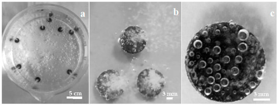
Figure 1.
Mg disks immersed in solution during carbonate coating: top views of (a) beaker with several Mg disks. (b) higher detail image, showing the gas column emanating from each disk, (c) one disk after 1 h immersion.
Mg disks are left immersed for different times, from 15 min up to 1 week (144 h), in order to study the evolution of the surface by carbonate solution coating. The evolution of Mg disks is illustrated in the photographs in Figure 2, taken after immersion at increasing immersion times. The initial disks have a metallic shine (Figure 2a). The first effect after immersion is the loss of the metallic shine, observed almost immediately, and the darkening of the surface in various shades of gray while degasification of the carbonated water takes place (Figure 2b). Visual inspection of the disk reveals the gradual homogenization of the gray surface of the Mg disks with increasing immersion time during the first hour: after 1 h (Figure 2c), the original cutting lines on the surface of the metal are hardly noticeable. After more than one hour of immersion, surface modification becomes slower, as well as the evolution of gas bubbles. Leaving the disks in solution for longer times, from 1 day to 1 week, causes the development of irregular depositions with a lighter color, clearly observable over most of the disk surface after 1 week of immersion (Figure 2d).
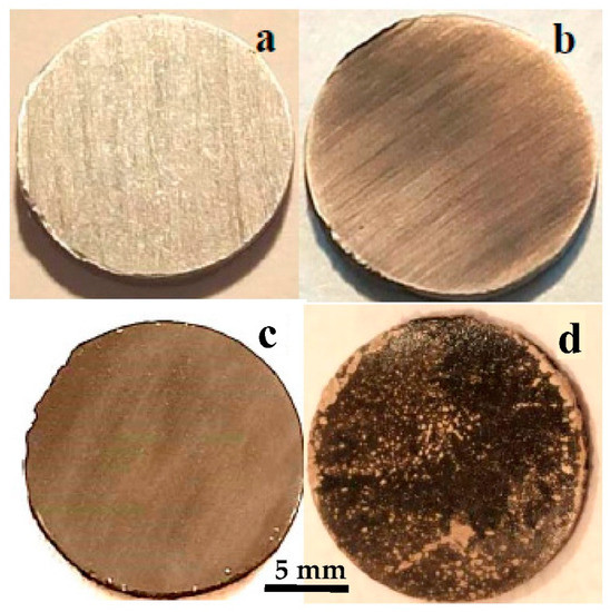
Figure 2.
Optical images showing the evolution with carbonatation time of Mg disks: (a) before immersion, and after (b) 15 min, (c) 1 h, (d) 1 week immersion times.
3.2. XRD, FTIR and Raman
XRD study of disks immersed in carbonated water revealed the formation of crystalline phases at the surface. Figure 3 shows the evolution of the XRD pattern for the bare Mg disk (Figure 3a) after one hour (Figure 3b). The XRD pattern after 1 h presents prominent Mg peaks, marked with ‘m’ in Figure 3a, and a strong additional feature at ~30 deg, corresponding to the main peak of calcite calcium carbonate -(014)-, accompanied by a doublet in the 47–49 deg region, characteristic of the second most intense feature of calcium carbonate -(018) and (116)-. Increased immersion times to 1 day (Figure 3c) results in the increase of the intensity of the main carbonate peaks relative to the metal peaks, which are still clearly observed. After one week, the metal peaks cannot be noticed in the XRD pattern, and instead, additional minor peaks, marked with ‘*’, appear in the pattern (Figure 3d) that can be indexed to aragonite, another allotrope of calcium carbonate (CaCO3) with orthorhombic symmetry. The relative intensity of the aragonite peaks is small, so the quantity of aragonite can be estimated at about one order of magnitude below that of calcite, as the main crystalline phase at the disk’s surface. The mechanistic crystallization of the coating along the surface by attaching oriented particles is discussed below in the manuscript (Section 3.5), explaining the two-dimensional growth of calcite coating, not in height, until completely coating the Mg surface. The magnesium content in the lattice of the calcite phase was determined using the method in ref [31], giving values of Mg presence between 1–2 mol%.
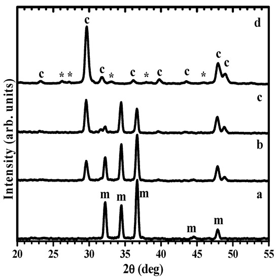
Figure 3.
XRD patterns showing the evolution with carbonatation time of Mg disks: (a) before immersion, and after (b) 1 h, (c) 1 day, (d) 1 week immersion times (c: calcite; *: aragonite; m: Mg).
The samples immersed less than 1h were additionally investigated by vibrational spectroscopy in order to study the presence of amorphous or disordered phases and ascertain the deposition of chemical species on the surface of Mg during the first hour of immersion in carbonated solution, previous to the crystallization of calcite observed in the XRD analysis.
The FTIR spectra of samples immersed for 1 h (Figure 4) displays the characteristic vibrations of the carbonate group in well -ordered, crystalline calcite, with a sharp peak at 713 cm−1 (υ4-symmetric CO3 bending) as well as the carbonate group vibrations at 873 cm−1 (υ2-asymmetric CO3 bending) and 1083 cm−1 (υ1-symmetric CO3 stretching) [32,33,34]. The sharp peak at 1796 is assigned to the υ1 + υ4 overtone. The FTIR spectra for 30 min immersion time exhibit weak υ4 and (υ1 + υ4) bands, with a clear decrease in the relative intensity between the υ4 and the υ2 bands, which indicates the predominance of disordered carbonate. The strong υ2 absorption band at ~866 cm−1 and the split peak at 1420 and 1475 cm−1 in the FT-IR spectra (Figure 4) have been described as characteristic of amorphous calcium carbonate (ACC) [35]. There are two main ACC absorptions around 1450 cm−1, as compared to a single absorption for the crystalline forms calcite and aragonite. The splitting is related to the υ3-asymmetric CO3 stretching around the carbonates. The vaterite allotrope of calcium carbonate, not detected in the XRD pattern, also has split FTIR peaks at ~1420–1490 cm−1 [36] but exhibits another distinctive peak at ~750 cm−1, not present in the spectra of treated Mg. Stable ACC, in contrast to the calcite and aragonite crystalline forms, does not present a sharp peak at 713 cm−1 [37]. Thus the absence of a peak at 713 cm−1 indicates that well -ordered calcite and/or aragonite are not present after 15 min immersion, only the presence of ACC can be determined from the FTIR analysis.
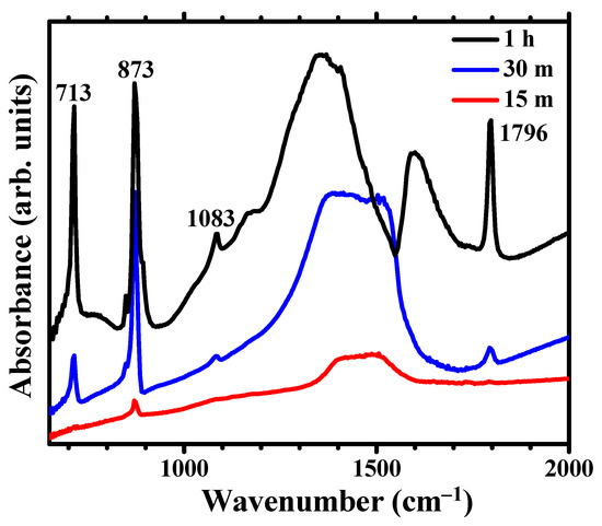
Figure 4.
FTIR spectra showing the evolution for immersion times in carbonated water of 15 min, 30 min and 1h.
The Raman spectra of Mg immersed for 1 h (Figure 5) have a strong, sharp feature at ~1086 cm−1. This band corresponds to the A1g mode of the CO3 polyhedra. Additional weaker features at ~711 cm−1, ~1433 and ~1746 cm−1 are assigned to internal Eg modes from the oscillations of the CO3 polyhedra in calcite calcium carbonate [38]. Raman results confirm XRD results, namely that after one -hour immersion, the coating is formed by crystalline calcite CaCO3. The Raman spectra after 30 min (Figure 5) also present a strong A1g mode of CO3 groups in CaCO3, as well as the secondary Eg modes. An additional weak band is observed at ~3650 cm−1. This band corresponds to OH group stretching and indicates the presence of hydroxyl groups along the CO3 polyhedra. The Raman spectra after 15 min present a weak carbonate peak and the hydroxyl band at 3648 cm−1 but do not show the calcite modes, therefore indicating the presence of disordered hydroxy carbonates.
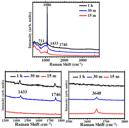
Figure 5.
Raman spectra showing the evolution for immersion times in carbonated water of 15 min, 30 min and 1h and details of the spectral regions of the Eg modes of calcite at 1300–1800 cm−1 and of OH stretching at 3500–3800 cm−1.
The analysis by vibrational spectroscopy exhibits distinctive features indicating the deposition of disordered carbonate phases, ACC and hydroxycarbonates, after 15 min immersion, as the result of Mg immersion in carbonated water.
3.3. SEM and EDS
The morphological evolution during the carbonatation treatment was investigated by SEM. Figure 6 shows micrographs from the samples immersed for 5 min (Figure 6a), 15 min (Figure 6b) and 30 min (Figure 6c,d). The sample immersed for 5 m exhibits the formation of a layer of nanoparticles covering the disk surface. These nanoparticles have typical sizes in the 20–30 nm, shown in the higher resolution image inside Figure 6a. The nanoparticle size may be correlated with an apparent equilibrium size for disordered nuclei grown in solution that are deposited on Mg in the first stage of carbonatation coating. The sample immersed for 15 min (Figure 6b) exhibits the formation of a second and more porous layer of nanoparticle aggregates. The aggregates tend to grow significantly into slightly elongated structures, sized in the hundreds of nms (inset in Figure 6b), leaving small areas of the inner nanoparticle layer still exposed, such as the darker gray area marked with an arrow in Figure 6b. This stage of carbonatation can be correlated with the observation by vibrational spectroscopy of the presence of ACC in the samples immersed for 15 min. The observed nanoparticles correspond with the formation of disordered phases. Figure 6c,d shows micrographs at different magnifications from the samples immersed for 30 min, taken in the top view from the center of the disks. Mg samples immersed for 30 min present rounded secondary aggregates, sized around 500 nm, which cover the whole disk surface and tend to coalesce into a dense layer. The aggregates are composed of much smaller elements, and the constituent primary nanoparticles, with sizes below 50 nm, can be identified at higher magnification images (inset in Figure 6d). At this stage, no faceted crystals can be observed, only short-range order phases. According to Raman and FT-IR, the observed nanoparticle aggregates correspond to amorphous carbonates.
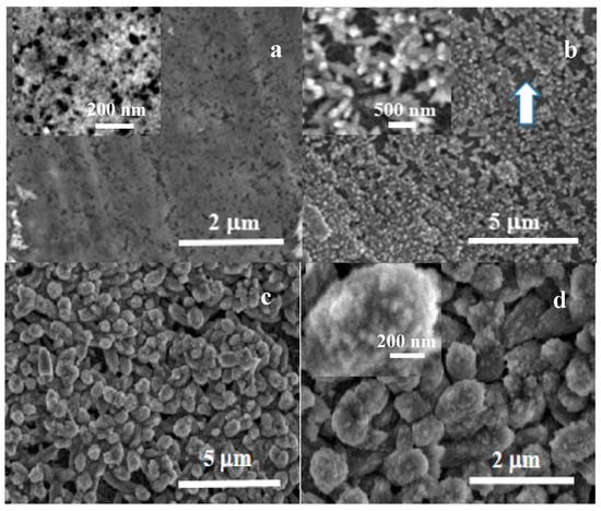
Figure 6.
SEM micrographs showing the evolution with carbonatation time of Mg disks after (a) 5 min, (b) 15 min, and (c,d) 30 min immersion times.
Figure 7 shows the surface morphology after carbonate coating for 1 h. Faceted calcite crystals, sized up to a few microns, can be observed forming aggregates of intertwined crystals. The surface of the crystals exhibits a patched ‘mosaic-like’ surface texture instead of being completely flat. The observed texture can be attributed to the growth of calcite crystals by the incorporation of amorphous carbonate nanoparticles from the solution on the preexisting crystal. A growth mechanism described previously as ‘crystallization by oriented nanoparticle attachment’ [39,40]. Table 1 displays the results of the elemental compositional analysis for bare Mg disks after immersion in carbonated water.
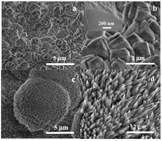
Figure 7.
SEM micrographs at different magnifications of Mg disks after (a,b) 1 h and (c,d) 1 -week immersion, showing rhombohedral calcite crystals (a,b) with a nanocrystalline mosaic pattern visible on the facets of growing calcite crystals (inset in (b)) and colonies of aragonite needle-like crystallites.

Table 1.
EDS compositional analysis after immersion treatment for 1 h.
Lateral growth is induced by the preferential nucleation and precipitation-deposition of amorphous carbonates at the areas of the Mg surface that are still exposed to oxidation. Crystallization and crystal growth thus permit the lateral growth and the coalescence of the calcite crystals layer after about 1 h immersion.
It is worth mentioning that the formation of brucite -magnesium hydroxide- crystals are not observed by any microstructural analysis during carbonatation. However, hydroxide is the natural corrosion product of Mg in an aqueous solution. Therefore, we must assume that the rapid deposition of amorphous nuclei from the solution inhibits the growth of a brucite corrosion layer, while hydroxyl groups are embedded in disordered hydroxycarbonate hydrated phases that are immersed in the carbonated solution and gradually transform into calcium carbonate by dehydroxylation and dehydration reactions.
Longer immersion times result in the observation by XRD of aragonite, another allotropic form of calcium carbonate. The study by SEM of samples immersed for one week revealed the formation of distinct morphologies other than the ordered calcite layer.
Figure 7c,d shows SEM micrographs of the semi-spherical aragonite colonies observed in a sample immersed for 1 week. These colonies have sizes in the tens to fifty microns (Figure 7c) and are composed of distinctive sharp-tipped needle-like crystals (Figure 7d) described previously as typical of aragonite [41]. The non-faceted, non-plate morphology shows no preferred orientation, forming non-compact depositions protruding from the compact calcite layer.
3.4. AFM
Figure 8 displays the tri-dimensional (Figure 8a) and the bi-dimensional (Figure 8b) AFM images of a bare Mg disk, scanned over an area of (5 µm × 5 µm), presented in so-called “enhanced contrast”, together with a typical profile-line (Figure 8c) that is a plot of a line scan collected along the scanning direction, marked to guide the eye by the red line in Figure 8b. The bare disk exhibits a succession of folds and valleys, arranged preferentially along one direction and probably formed during the cutting of the disks. However, the surface is flat, as can be observed from the line scan in Figure 8c, which shows that the surface features are located in a vertical range of ~80 nm (see the vertical scale of the surface profile, from −40 to +40 nm). The root mean square (RMS) roughness of the image presented in Figure 8b is 18.5 nm, while the average roughness value equals 14.1 nm.
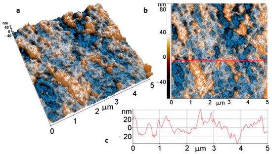
Figure 8.
Tri-dimensional (a) and bi-dimensional (b) AFM images and line profile (c) of bare Mg.
Figure 9 shows AFM images of the Mg disk after immersion for 15 min in carbonated solution at (8 µm × 8 µm) scale. Figure 9a,b display a compact layer of ACC resulting from carbonatation, forming the massive agglomeration of material that covers the Mg surface and a top layer of rounded protruding aggregates of a few hundred nm in diameter, such as the particle marked between the two red arrows in Figure 9c (~190 nm diameter). The layer shown in the 3D AFM image (Figure 9a) has increased values of roughness (Table 2), for example, Rq = 328.7 nm, while the peak-to-valley parameter, on the whole area, is Rpv ~1.93 µm, estimated based on the 2D AFM image in Figure 9b, therefore about 25 times higher than that of the bare Mg surface (Figure 8).
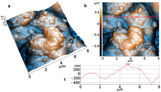
Figure 9.
Tri-dimensional (a), bi-dimensional (b) AFM images taken on areas of 8 µm × 8 µm and AFM line profile (c) of Mg after immersion for 15 min, along the scanning direction marked to guide the eye by the red line in (b).
Table 2.
Roughness parameters (Rq, Ra, Rpv) evolution with immersion time.
AFM images of the Mg disk after 1h immersion (Figure 10), scanned over an area of (8 µm × 8 µm), present a completely different morphology, consisting of stacked faceted crystallites of hundreds of nm overlapped in the form of steps and terraces (stairs-like). As suggested by the 3D image from Figure 10a and the linescan from Figure 10c, the spatial arrangement of the faceted crystallites leads to a stepped surface, as proved by the increased values of the roughness parameters: Rq = 509.6 nm, and Rpv = 3.69 µm.
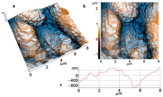
Figure 10.
Tri-dimensional (a) and bi-dimensional (b) AFM images and line profile (c) of Mg surface after 1h immersion.
Further on, for an immersion time of 1 day, the AFM images in Figure 11, also scanned over an area of (8 µm × 8 µm), show much larger faceted crystals, with dimensions of a few microns (see Figure 11a,b). The coating preserves the compact morphology, but a finer surface texture is suggested by the aspect of some exposed crystal facets. However, at the (8 µm × 8 µm) scale, the roughness parameters are similar to the values obtained from the sample immersed for 1 h in Figure 10, as follows: Rq = 478.1 nm, and Rpv = 3.21 µm (Figure 11c).
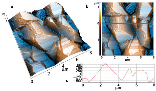
Figure 11.
Tri-dimensional (a), bi-dimensional (b) AFM images taken on areas of: 8 µm × 8 µm; and AFM line profile (c) of Mg after 1 -day immersion.
Figure 12 shows the measured contact angles of the Mg disks before and after the carbonate coating treatment. The bare disks exhibit contact angles of ~60 deg. After immersion for 30 min, the contact angle increase to values ~80 deg, and a maximum contact angle of ~130 deg was measured for samples treated in carbonated water for 1 h.
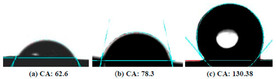
Figure 12.
Contact angle images for droplets of water on Mg disks: (a) before immersion, (b) after 30 min, (c) after 1 h immersion time.
The increase in contact angle can be attributed to the texture of the coating, as evidenced by the AFM measurements, with the development of faceted surfaces and clear-cut steps of hundreds of nanometers depth between adjacent calcite crystallites. We attribute the observed hydrophobicity of the coated disks to the observed evolution of rugosity in the calcite layer.
3.5. Coating Formation Stages
The formation mechanism of the calcite coating layer on Mg immersed in a carbonated aqueous solution containing HCO3−/CO2 and Ca2+ involves a process with several stages.
3.5.1. Surface Conversion to Hydroxycarbonates
The results demonstrate that carbonatation coating inhibits the formation of a magnesium hydroxide layer. This is the first coating stage, namely the rapid deposition from the solution, supersaturated in bicarbonate ions, of carbonates groups that combine with hydroxyl groups on the surface of Mg. Gradually, the formation of stable, non-soluble hydroxycarbonates stabilizes the Mg surface, while soluble OH− groups enter the solution.
We can resume this stage as surface conversion to hydroxycarbonates. Our explanation of the substitution of hydroxyl groups with carbonates is related to the locally increased pH associated with the oxidized Mg surface, according to the hydroxylation reaction (1), which favours the decomposition of bicarbonates into carbonates groups and hydroxyl substitution by carbonates at the surface:
Mg0 + 2H2O ↔ Mg(OH)2 + H2
xMg(OH)2 + yHCO3− ↔ Mgx(CO3)y(OH)2(x−y) + yH2O+ yOH−
The chemical Equation (2) inhibits the formation of a hydroxide layer promoting the nucleation of amorphous hydroxycarbonate hydrates, according to the Raman and FTIR results. The first stage is key for the formation of the carbonate coating, not only by impeding the formation of a hydroxide layer but also because hydroxycarbonate hydrates are a propitious surface for the deposition of calcium carbonate.
This coating stage presents the advantage of full coverage of the Mg surface, explained because the nucleation of carbonate and deposition is favored at the surface of Mg wherever hydroxide groups have been formed, and their substitution with non-soluble carbonates is promoted. Once lateral growth is complete, the growth of the coating is hampered and limited to nanoparticle attachment on growing calcite crystals.
The pH values of the solution measured during immersion evidenced a gradual increase in time toward more alkaline values (Figure 13). However, measurements of the pH of the solution with time in the absence of Mg also revealed a similar increase of the pH values (Figure 13), attributed to reaction (4) of dissolved hydrogen carbonate ions in carbonated water, accompanied by the evolution of CO2. Therefore, the main cause of the pH increase can be attributed to the free evolution of CO2 at atmospheric pressure. A further increase in pH may occur associated with the release of hydrogen at the metal surface according to reaction (1) and the subsequent release of hydroxide ions into the solution following reaction (2), leading to higher pH values at the Mg surface. However, the effect is relatively small in the bulk solution.
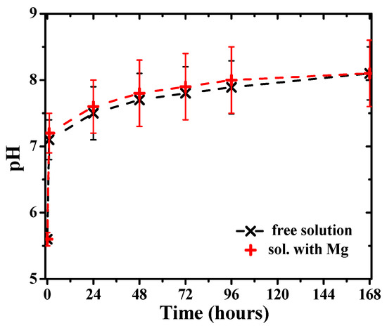
Figure 13.
pH evolution of the carbonated water solution in the presence of Mg disks and without them (free solution).
3.5.2. Carbonatation
The second stage of the coating formation is the formation of calcium carbonate, according to reaction (3)
Ca2+(Mg2+) + HCO3− ↔ Ca2+ (Mg2+) + CO32− + H+ ↔ Ca(Mg)CO3↓ + H+
Precipitation of carbonates from carbonated aqueous solution is strongly dependent on factors such as pH, temperature and solution composition. Calcium carbonate solubility increases with CO2 content in the solution, so precipitation of carbonate groups continues while CO2(g) is released into the atmosphere from the carbonating solution. The release of hydroxyls at the Mg surface due to the exchange of OH− by CO32− also shifts the equilibrium in reaction (3) towards the precipitation at the surface of Ca(Mg)CO3 magnesian calcite. We can resume this stage as precipitation of calcium carbonate or carbonatation. Carbonatation takes place by multiple nucleations of ACC nanoparticles and lateral growth onto the Mg surface until the formation of the ACC calcium carbonate layer is observed by SEM and AFM. This coating stage leads to the complete coverage of the Mg surface with ACC. The presence of Mg2+ greatly increases ACC stability [42], facilitating the deposition of ACC clusters.
3.5.3. Crystallization and Lateral Growth
The third stage is the crystallization of calcite and lateral growth through the attachment of calcium carbonate nanoparticles until the formation of a compact crystalline film coating the Mg disk. The process of transforming ACC into calcite takes place at the same time as ACC nuclei continue to be deposited from the solution, incorporating into growing calcite crystals until full protective coverage is formed and the calcite bi-dimensional growth comes to an end due to the coalescence of the growing crystals. We can name this stage crystallization and lateral growth.
When the coverage of the disk by calcite crystals is complete, the deposition of additional carbonates from the saturated solution results in non-homogeneous, irregular deposits that cannot be considered a constituent part of the calcite coating layer, forming loosely attached deposits on top of the calcite layer, particularly aragonite colonies. We can name this last stage excessive growth (in height, so three-dimensional excessive growth). The four stages are illustrated in Figure 14.
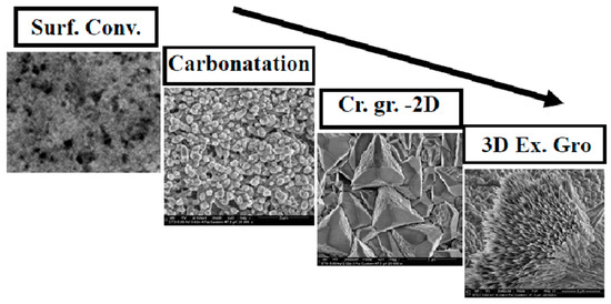
Figure 14.
Flux diagram illustrating the identified stages of carbonate coating.
4. Conclusions
Carbonate deposition from carbonated water at atmospheric pressure and room temperature can be a safe and technically simple technique highly efficient for surface modification of biomedical Mg and alloys by rapid deposition of carbonate clusters and nanoparticles in non-equilibrium conditions from a saturated carbonated aqueous solution containing calcium ions.
The coating of Mg by a compact crystalline layer of magnesian calcite has been presented. The mechanism of calcite formation involves the rapid deposition of carbonates groups that substitute hydroxyl groups on the surface of Mg, a key step for the formation of the coating, as non-soluble hydroxycarbonates inhibit the formation of Mg(OH)2 at the Mg surface, impeding the growth of a hydroxide layer resulting from the natural oxidation of Mg in water, hydroxide anions being replaced rapidly by carbonate groups at the oxidized metal surface. We have named this stage surface conversion to hydroxycarbonates. The substitution of soluble hydroxides with insoluble carbonates is promoted by the increased pH associated with the oxidation of the Mg surface in an aqueous solution.
Carbonatation or deposition of a surface layer of amorphous calcium carbonate nanoparticles from the solution, due to reduced solubility when gaseous CO2(g) is released, takes place after approximately 15 min of immersion in carbonated water. After 30 min of immersion, crystallization of calcite is demonstrated and growth by nanoparticle attachment due to the incorporation of amorphous carbonate from the solution, which seems to be the precursor for the crystallization of calcite, leading to the formation of a continuous layer of euhedral calcite crystals that cover the whole disk surface after one hour of immersion. SEM and AFM observations confirm that the calcite coating is continuous and that lateral growth of the calcite nuclei leads to bi-dimensional coalescence to a polycrystalline coating layer. The full surface coverage of the disk, by the formation of a dense coating of intersecting crystals, results in a characteristic texture of crystalline steps between neighboring calcite crystals that confers hydrophobicity to the calcite coating.
We conclude that carbonate films grown by green chemistry on magnesium have a high potential to be used as a non-toxic protective barrier to modulate the physicochemical properties of the magnesium surface, for example, in the physiological environment, with possible application in biodegradable implants, in where biocompatibility assessment is required.
Author Contributions
Conceptualization and methodology J.M.C.M. and M.P.; formal analysis and investigation, J.M.C.M., M.P., M.A. and I.C.G.; writing—original draft preparation, review and editing J.M.C.M., M.A. and M.P.; project administration and funding acquisition, J.M.C.M. All authors have read and agreed to the published version of the manuscript.
Funding
This research was funded by the Executive Unit for the Financing of Higher Education, Research, Development, and Innovation (UEFISCDI) Exploratory Research Project PN-III-P4-ID-PCE-2020-0992 (PCE-234/2021).
Institutional Review Board Statement
Not applicable.
Data Availability Statement
The data presented in this study are available on request from the corresponding author.
Acknowledgments
The paper was carried out within the research program “Science of Surfaces and Thin Layers” of the “Ilie Murgulescu” Institute of Physical Chemistry. The support of the Romanian Government that allowed for the acquisition of the research infrastructure under POSCCE O 2.2.1 project INFRANANOCHEM—No. 19/01.03.2009 9 is gratefully acknowledged.
Conflicts of Interest
The authors declare no conflict of interest. The funders had no role in the design of the study; in the collection, analyses, or interpretation of data; in the writing of the manuscript; or in the decision to publish the results.
References
- Sheikh, Z.; Najeeb, S.; Khurshid, Z.; Verma, V.; Rashid, H.; Glogauer, M. Biodegradable Materials for Bone Repair and Tissue Engineering Applications. Materials 2015, 8, 5744–5794. [Google Scholar] [CrossRef] [PubMed]
- Chen, J.; Tan, L.; Yu, X.; Etim, I.P.; Ibrahim, M.; Yang, K. Mechanical properties of magnesium alloys for medical application: A review. J. Mech. Behav. Biomed. Mater. 2018, 87, 68–79. [Google Scholar] [CrossRef] [PubMed]
- Schuchardt, J.P.; Hahn, A. Intestinal Absorption and Factors Influencing Bioavailability of Magnesium—An Update. Curr. Nutr. Food Sci. 2017, 13, 260–278. [Google Scholar] [CrossRef] [PubMed]
- Herber, V.; Okutan, B.; Antonoglou, G.; Sommer, N.G.; Payer, M. Bioresorbable Magnesium-Based Alloys as Novel Biomaterials in Oral Bone Regeneration: General Review and Clinical Perspectives. J. Clin. Med. 2021, 10, 1842. [Google Scholar] [CrossRef] [PubMed]
- Lin, X.; Tan, L.; Zhang, Q.; Yang, K.; Hu, Z.; Qiu, J.; Cai, Y. The in vitro degradation process and biocompatibility of a ZK60 magnesium alloy with a forsterite-containin,g micro-arc oxidation coating. Acta Biomater. 2013, 9, 8631–8642. [Google Scholar] [CrossRef]
- Song, G. Control of biodegradation of biocompatable magnesium alloys. Corros. Sci. 2007, 49, 1696–1701. [Google Scholar] [CrossRef]
- Geng, F.; Tan, L.; Jin, X.; Yang, J.; Yang, K. The preparation, cytocompatibility, and in vitro biodegradation study of pure β-TCP on magnesium. J. Mater. Sci. 2009, 20, 1149–1157. [Google Scholar] [CrossRef]
- Wen, C.; Guan, S.; Peng, L.; Ren, C.; Wang, X.; Hu, Z. Characterization and degradation behavior of AZ31 alloy surface modified by bone-like hydroxyapatite for implant applications. Appl. Surf. Sci. 2009, 255, 6433–6438. [Google Scholar] [CrossRef]
- Song, Y.; Zhang, S.; Li, J.; Zhao, C.; Zhang, X. Electrodeposition of Ca–P coatings on biodegradable Mg alloy: In vitro biomineralization behavior. Acta Biomater. 2010, 6, 1736–1742. [Google Scholar] [CrossRef]
- Habibovic, P.; Barrere, F.; Blitterswijk, C.A.; Groot, K.; Layrolle, P. Biomimetic hydroxyapatite coating on metal implants. J. Am. Ceram. Soc. 2002, 85, 517–522. [Google Scholar] [CrossRef]
- Cui, W.; Beniash, E.; Gawalt, E.; Xu, Z.; Sfeir, C. Biomimetic coating of magnesium alloy for enhanced corrosion resistance and calcium phosphate deposition. Acta Biomater. 2013, 9, 8650–8659. [Google Scholar] [CrossRef] [PubMed]
- Chiu, K.Y.; Wong, M.H.; Cheng, F.T.; Man, H.C. Characterization and corrosion studies of fluoride conversion coating on degradable Mg implants. Surf. Coat. Technol. 2007, 202, 590–598. [Google Scholar] [CrossRef]
- Yan, T.; Tan, L.; Xiong, D.; Liu, X.; Zhang, B.; Yang, K. Fluoride treatment and in vitro corrosion behavior of an AZ31B magnesium alloy. Mater. Sci. Eng. C 2010, 30, 740–748. [Google Scholar] [CrossRef]
- Gu, X.N.; Zheng, W.; Cheng, Y.; Zheng, Y.F. A study on alkaline heat treated Mg–Ca alloy for the control of the biocorrosion rate. Acta Biomater. 2009, 5, 2790–2799. [Google Scholar] [CrossRef]
- Brennan, S.T.; Lowenstein, T.K.; Horita, J. Seawater chemistry and the advent of biocalcification. Geology 2004, 32, 473–476. [Google Scholar] [CrossRef]
- Ivanov, V.; Stabnikov, V. Calcite/aragonite-biocoated artificial coral reefs for marine parks. AIMS Environ. Sci. 2017, 4, 586–595. [Google Scholar] [CrossRef]
- Liu, Y.; Jiang, T.; Zhou, Y.; Zhang, Z.; Wang, Z.; Tong, H.; Shen, X.; Wang, Y. Evaluation of the attachment, proliferation, and differentiation of osteoblast on a calcium carbonate coating on titanium surface. Mater. Sci. Eng. C 2011, 31, 1055–1061. [Google Scholar] [CrossRef]
- Al-Abdullat, Y.; Tsutsumi, S.; Nakajima, N.; Ohta, M.; Kuwahara, H.; Ikeuchi, K. Surface modification of magnesium by NaHCO3 and corrosion behavior in Hank’s solution for new biomaterial applications. Mater. Trans. 2001, 42, 1777–1780. [Google Scholar] [CrossRef]
- Sathyaraj, P.M.; Ravichandran, K.; Narayanan, T.S.N.S. Improving the corrosion resistance and bioactivity of magnesium by a carbonate conversion-polycaprolactone duplex coating approach. New J. Chem. 2020, 44, 4772–4785. [Google Scholar]
- Jia, S.; Guo, Y.; Zai, W.; Su, Y.; Yuan, S.; Yu, X.; Xu, Y.; Li, G. Preparation and characterization of a composite coating composed of polycaprolactone (PCL) and amorphous calcium carbonate (ACC) particles for enhancing corrosion resistance of magnesium implants. Prog. Org. Coat. 2019, 136, 105225. [Google Scholar] [CrossRef]
- Uan, J.Y.; Yu, B.L.; Pan, X.L. Morphological and Microstructural Characterization of the Aragonitic CaCO3/Mg,Al-Hydrotalcite Coating on AZ91 Alloy to Protect against Corrosion. Met. Mater. Trans. A 2008, 39A, 3233–3245. [Google Scholar] [CrossRef]
- Yu, B.L.; Pan, X.L.; Uan, J.Y. Enhancement of corrosion resistance of Mg-9 wt.% Al-1 wt.% Zn alloy by a calcite (CaCO3) conversion hard coating. Corros. Sci. 2010, 52, 1874–1878. [Google Scholar] [CrossRef]
- Zuleta, A.A.; Correa, E.; Villada, C.; Sepúlveda, M.; Castaño, J.G.; Echeverría, F. Comparative study of different environmentally friendly (Chromium-free) methods for surface modification of pure magnesium. Surf. Coat. Technol. 2011, 205, 5254–5259. [Google Scholar] [CrossRef]
- Prabhu, D.B.; Gopalakrishnan, P.; Ravi, K.R. Morphological studies on the development of chemical conversion coating on surface of Mge4Zn alloy and its corrosion and bio mineralisation behaviour in simulated body fluid. J. Alloy. Compd. 2020, 812, 152146. [Google Scholar] [CrossRef]
- Lin, J.K.; Uan, J.Y.; Wu, C.P.; Huang, H.H. Direct growth of oriented Mg–Fe layered double hydroxide (LDH) on pure Mg substrates and in vitro corrosion and cell adhesion testing of LDH-coated Mg samples. J. Mater. Chem. 2011, 21, 5011–5020. [Google Scholar] [CrossRef]
- Guo, L.; Wu, W.; Zhou, Y.; Zhang, F.; Zeng, R.; Zeng, J. Layered double hydroxide coatings on magnesium alloys: A review. J. Mater. Sci. Technol. 2018, 34, 1455–1466. [Google Scholar] [CrossRef]
- Wang, Y.; Liu, B.; Zhao, X.; Zhang, X.; Miao, Y.; Yang, N.; Yang, B.; Zhang, L.; Kuang, W.; Li, J.; et al. Turning a native or corroded Mg alloy surface into an anti-corrosion coating in excited CO2. Nat. Commun. 2018, 9, 4058. [Google Scholar] [CrossRef]
- Cao, X.; Ren, Q.; Yang, Y.; Hou, X.; Yan, Y.; Hu, J.; Deng, H.; Yu, D.; Lan, W.; Pan, F. A new environmentally-friendly route to in situ form a high-corrosion-resistant nesquehonite film on pure magnesium. RSC Adv. 2020, 10, 35480–35489. [Google Scholar] [CrossRef]
- Jiang, P.; Hou, R.; Zhu, S.; Guan, S. A robust calcium carbonate (CaCO3) coating on biomedical MgZnCa alloy for promising corrosion protection. Corros. Sci. 2022, 198, 110124. [Google Scholar] [CrossRef]
- Popa, M.; Stefan, L.M.; Prelipcean, A.M.; Drob, S.I.; Anastasescu, M.; Calderon Moreno, J.M. Inhibition of Mg corrosion in physiological fluids by carbonate coating. Corros. Sci. 2022, in press. [CrossRef]
- Fahad, M.; Saeed, S. Determination and estimation of magnesium content in the single phase magnesium-calcite [Ca(1−x)MgxCO3(s)] using electron probe micro-analysis (EPMA) and X-ray diffraction (XRD). Geosci. J. 2018, 22, 303–312. [Google Scholar] [CrossRef]
- Chu, D.H.; Vinoba, M.; Bhagiyalakshmi, M.; Baek, I.H.; Nam, S.C.; Yoon, Y.; Kim, S.H.; Jeong, S.K. CO2 mineralization into different polymorphs of CaCO3 using an aqueous-CO2 system. RSC Adv. 2013, 3, 21722–21729. [Google Scholar] [CrossRef]
- Khouzani, M.F.; Chevrier, D.M.; Güttlein, P.; Hauser, K.; Zhang, P.; Hedinc, N.; Gebauer, D. Disordered amorphous calcium carbonate from direct precipitation. CrystEngComm 2015, 17, 4842–4849. [Google Scholar] [CrossRef]
- Gunasekaran, S.; Anbalagan, G.; Pandi, S. Raman and infrared spectra of carbonates of calcite structure. J. Raman Spectrosc. 2006, 37, 892–899. [Google Scholar] [CrossRef]
- Addadi, L.; Raz, S.; Weiner, S. Taking Advantage of Disorder: Amorphous Calcium Carbonate and Its Roles in Biomineralization. Adv. Mater. 2003, 15, 959–970. [Google Scholar] [CrossRef]
- Ma, Y.; Feng, Q. A crucial process: Organic matrix and magnesium ion control of amorphous calcium carbonate crystallization on β-chitin film. CrystEngComm 2015, 17, 32–39. [Google Scholar] [CrossRef]
- Ismaiel-Saraya, M.; Rokbaa, H. Formation and Stabilization of Vaterite Calcium Carbonate by Using Natural Polysaccharide. Adv. Nanoparticles 2017, 6, 158–182. [Google Scholar] [CrossRef]
- Dufresne, W.J.B.; Rufledt, C.J.; Marshall, C.P. Raman spectroscopy of the eight natural carbonate minerals of calcite structure. J. Raman Spectrosc. 2018, 49, 1999–2007. [Google Scholar] [CrossRef]
- Nishino, Y.; Oaki, Y.; Imai, H. Magnesium-Mediated Nanocrystalline Mosaics of Calcite. Cryst. Growth Des. 2009, 9, 223–226. [Google Scholar] [CrossRef]
- de Yoreo, J.J.; Gilbert, P.U.P.A.; Sommerdijk, N.A.J.M.; Penn, R.L.; Whitelam, S.; Joester, D.; Zhang, H.; Rimer, J.D.; Navrotsky, A.; Banfield, J.F.; et al. Crystallization by particle attachment in synthetic, biogenic, and geologic environments. Science 2015, 349, 6247. [Google Scholar] [CrossRef]
- Wang, L.; Sondi, I.; Matijević, E. Preparation of Uniform Needle-Like Aragonite Particles by Homogeneous Precipitation. J. Colloid Interface Sci. 1999, 218, 545–553. [Google Scholar] [CrossRef] [PubMed]
- Loste, E.; Wilson, R.M.; Seshadri, R.; Meldrum, F.C. The role of magnesium in stabilising amorphous calcium carbonate and controlling calcite morphologies. J. Cryst. Growth 2003, 254, 206–218. [Google Scholar] [CrossRef]


Publisher’s Note: MDPI stays neutral with regard to jurisdictional claims in published maps and institutional affiliations. |
© 2022 by the authors. Licensee MDPI, Basel, Switzerland. This article is an open access article distributed under the terms and conditions of the Creative Commons Attribution (CC BY) license (https://creativecommons.org/licenses/by/4.0/).