Rapid prototyping (RP) is a growing technology in maxillofacial trauma and will have a significant role in the surgical planning and reconstruction of such defects in the future. Although stereolithographic biomodels have been available for many years, RP offers an economic method of biomodel fabrication.[
1] Further advantages in orbital reconstruction include ability for exact preadaption of a titanium implant to the fracture configuration[
1,
2,
3,
4](
Figure 1) leading to a reduction in treatment time, tissue trauma, and restoration of orbital form.[
1,
5]
Hoelzle et al[
6] were among the first to document the benefits of intraoperative scanning. It has since been used by some authors with the aim of eliminating malposition of implants and the need for revision surgery in midface trauma.[
7,
8]
This article evaluates the treatment protocols and clinical outcome of orbital floor fractures reconstructed with the aid of both technologies.
Methods
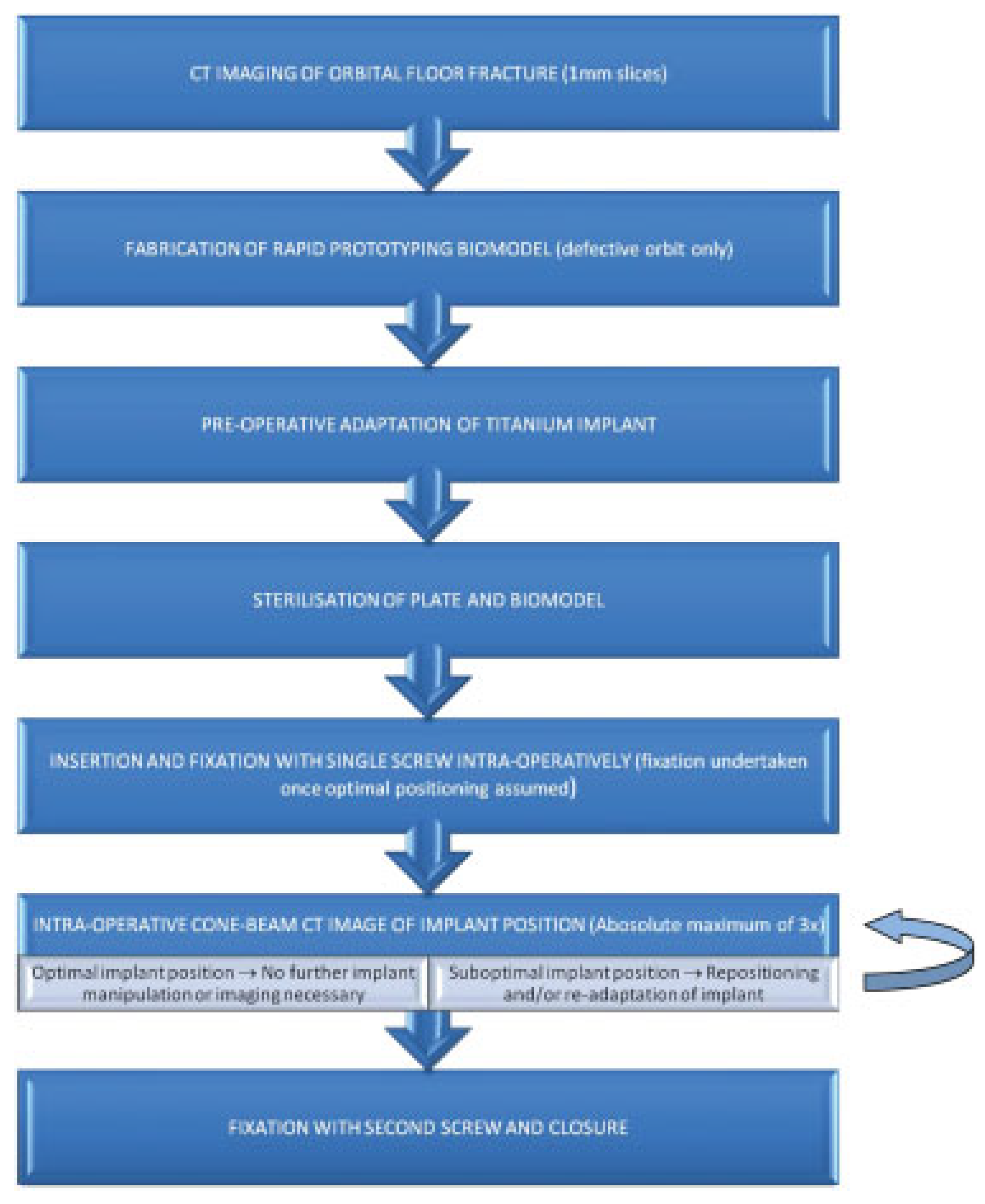
The treatment protocol (
Figure 2) was the same used by an earlier case report by Lim et al.[
1] Patients who sustained pure orbital floor fractures not involving the zygomatic complex, orbital rim, and/or the medial orbital wall were identified over a 12-month period. Orbital floor defects greater than 1 cm
2 was the parameter required for operative intervention. Computed tomography (CT) imaging and subjective assessment of enophthalmos, diplopia, and infraorbital paresthesia were recorded if present. Those patients who did not have RP were not included in this series.
For each patient, a RP biomodel was fabricated using the patient’s CT data. Only the defective anatomy was used for modeling the orbital defect which allowed adequate access and evaluation of implant adaptation to the fracture. The biomodels were designed using the three-dimensional (3D) Slicer platform[
9] (
www.slicer.org) and built with the UP!3d printer (
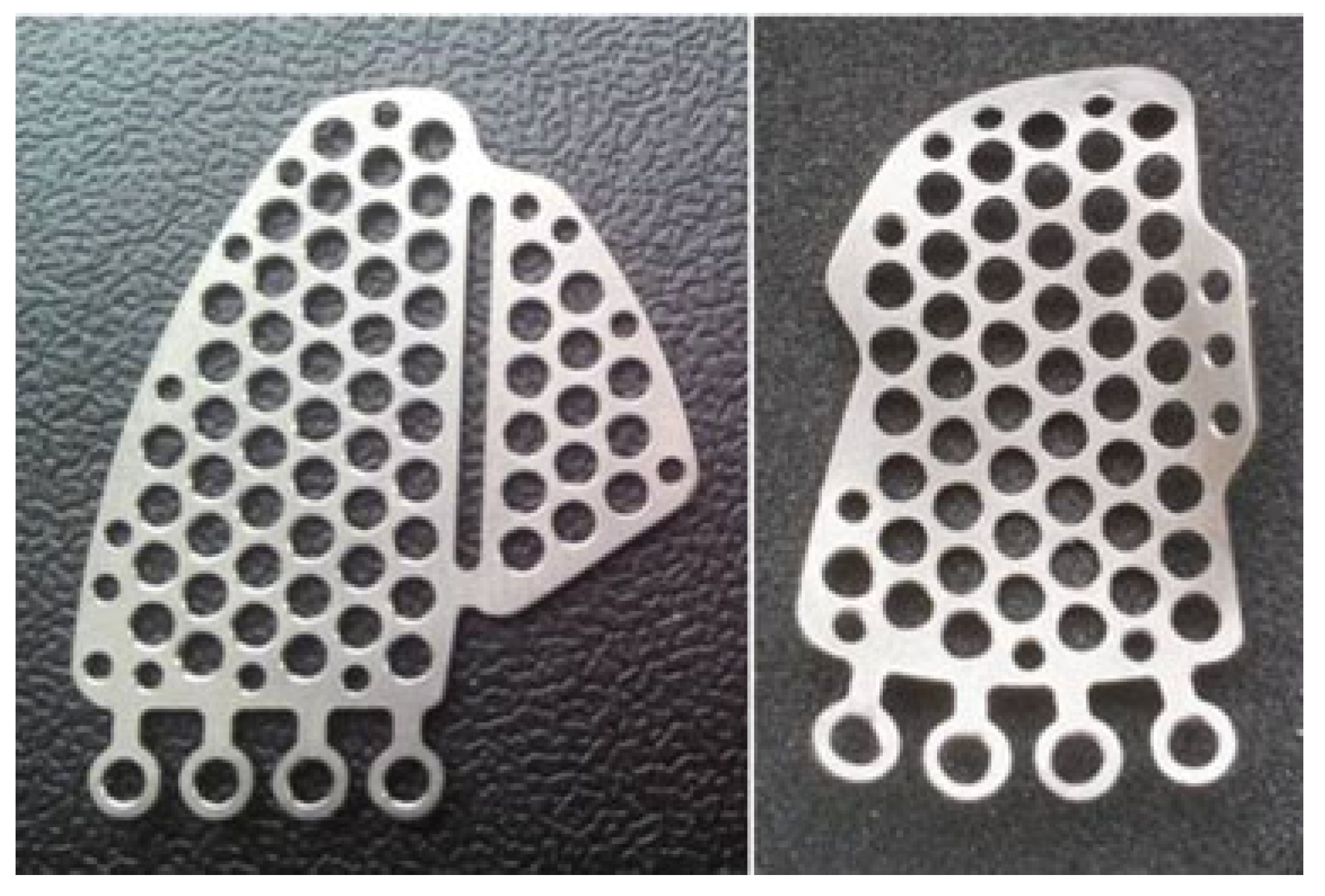
www.pp3dp.com). The implants were either Synthes (Synthes, West Chester, Pennsylvania) Matrix MIDFACE Preformed Orbital Plates or “in-house” fabricated titanium implants manufactured in a ISO certified (ISO 9001) bioengineering facility in our district health board (
Figure 3).
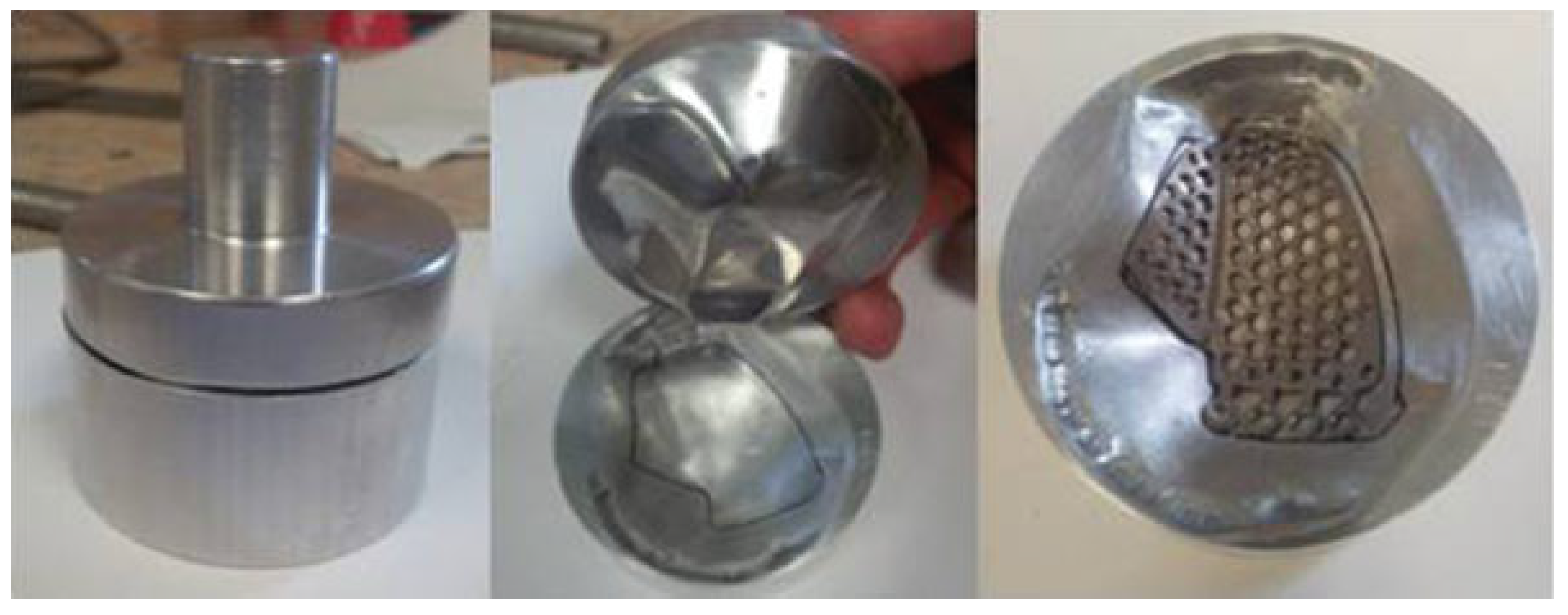
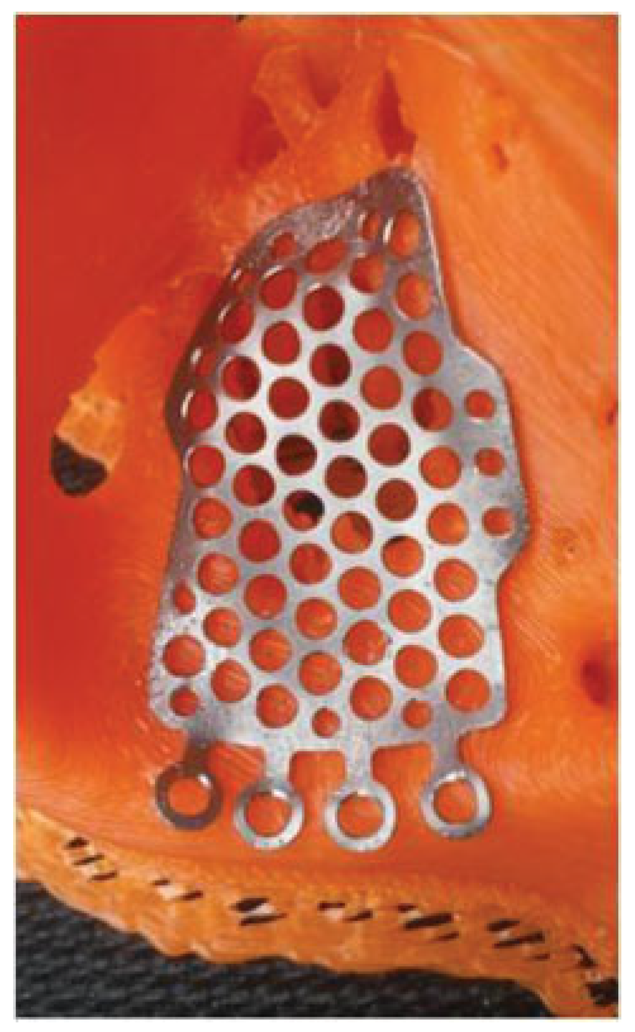
These were 0.5-mm-thick B-265 grade 2 sheet titanium alloy certified by ASTM International (American Society for Testing and Materials, West Conshohocken, PA) which was cut to one of several standard designs for orbital floor defects and further molded with a stainless steel press (
Figure 4).
The plates were further manipulated and if necessary trimmed according to the size of the defect (
Figure 5). Both the biomodel and the titanium plate were sterilized before the procedure, the plate was treated and polished to remove surface impurities and any sharp edges that may cause unnecessary tissue injury.
A transconjunctival or subtarsal approach as described by Ellis and Zide[
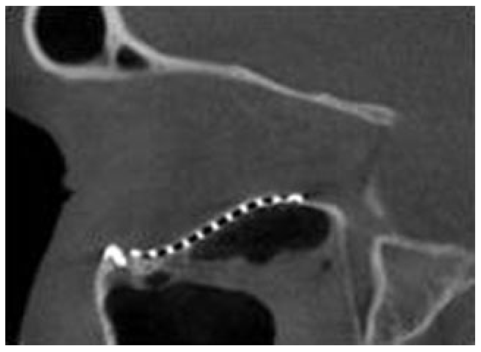
10] was used to access the orbital floor and subperiosteal dissection was undertaken to expose the fracture and its margins. The time was recorded from the moment the operator handled the implant until it was secured with the first screw. An intraoperative CT scan (O-arm, Medtronics, Minneapolis, MN) was used to evaluate the position of the implant and if not positioned optimally, was adjusted and rescanned with an absolute maximum of three scans per patient. The time taken for readjustment was also recorded and totaled to give the “duration of plate placement.” The parameters evaluated were the position of the plate over the posterior ledge, the medial and lateral margins of the fracture (
Figure 6), and the anatomical contour in an anteroposterior dimension in regard to restoring the posterior bulge (
Figure 7). When an optimal position of the implant was achieved, a forced duction test was undertaken to ensure that the globe was free and a second screw was used for additional fixation. The surgical wounds were then closed. The number of intraoperative CTscans needed was also noted. Intraoperative imaging was occasionally unavailable due to time constraints and facility availability. In these cases, a postoperative cone beam CT (i-CAT, Imaging Sciences International, Hatfield, PA) was used postoperatively within 24 hours to evaluate the implant position.
All patients were followed up for at least 6 weeks at the time of writing and the parameters assessed were presence of diplopia, infraorbital paresthesia, enophthalmos, and restoration of orbital form.
Results
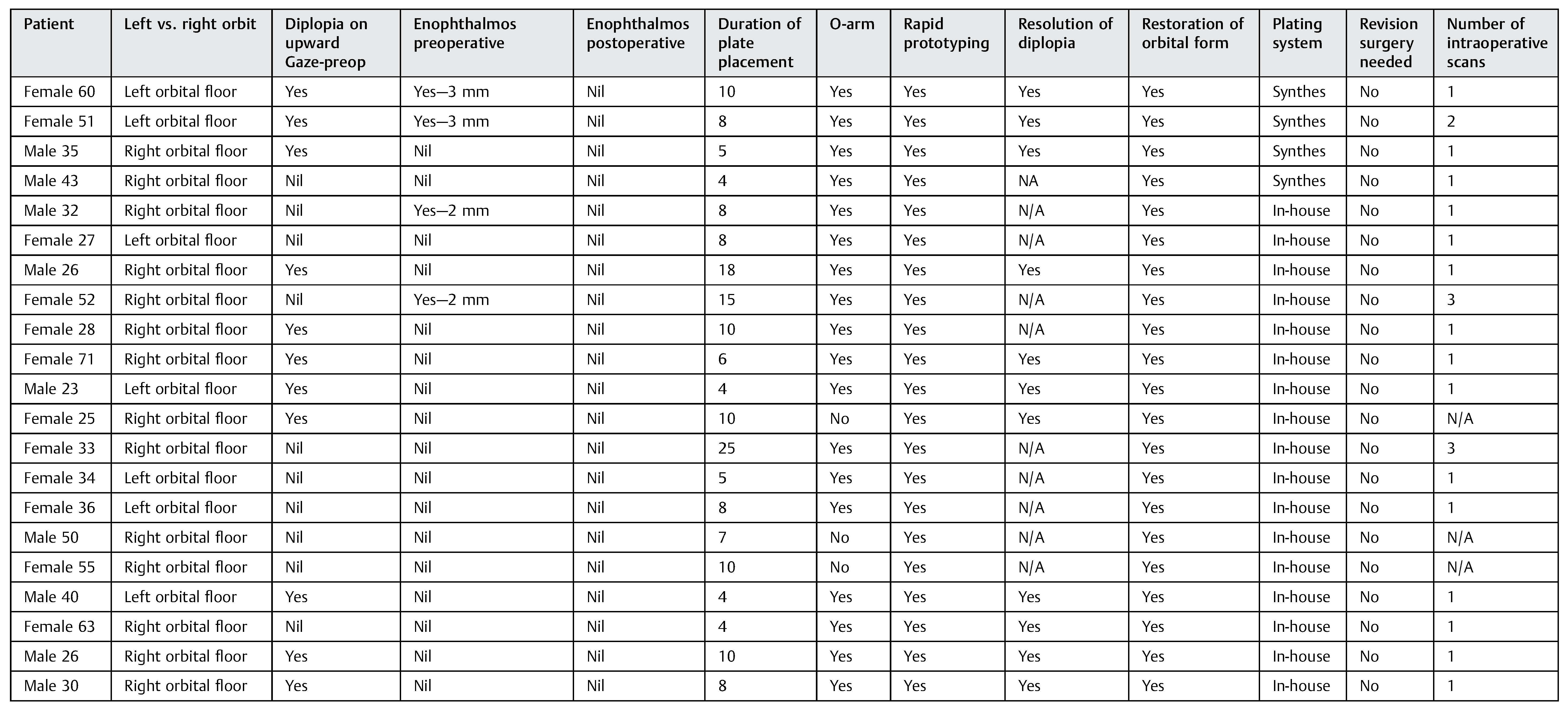
A total of 21 patients were evaluated over a 12-month period (
Table 1). All 21 patients used a RP biomodel and 18 patients underwent intraoperative CT evaluation. None of these patients needed revision surgery.
The time taken for implant positioning and fixation ranged from 4 to 25 minutes (
Figure 8). Orbital floor form was assessed radiographically after implant insertion and in all cases found to be flush with the posterior ledge. Furthermore, the reconstructed posterior bulge “key area” was present in all cases.
Enophthalmos correction was assessed with O-arm and cone beam 3D images and a subjective clinical assessment was made postoperatively. This resolved in those patients who presented with this. Clinical examination confirmed resolution of diplopia in patients who initially presented with this symptom.
Discussion
RP is increasingly used in surgical diagnosis and treatment planning. An accurate 3D model allows visualization of the surgical defect and its surrounding anatomy giving the operator an intimate knowledge of the fracture configuration once examined. Preadapting an implant for reconstruction of the orbital floor has several advantages. The first allows accurate reconstruction of the surgical defect with ideal orbital floor form reducing the risk of implant malposition and the need for revision surgery. A significant reduction in implant positioning time leads to a reduction in tissue trauma, operator fatigue, and stress. Finally, RP is a cost-effective method which can be readily accessed.[
1]
Reconstruction of orbital floor defects has had high complication rates previously. Hoelzle et al[
6] found that 15% of a series of patients who underwent repair of orbitozygomatic complex fractures required revision when intraoperative CT scanning was used. Complications such as plate malposition and entrapment of soft tissue have been well documented particularly in the deep orbit. Posterior landmarks are often difficult to visualize and re-establishing orbital contours with correct projection of the posterior bulge can be difficult. The plate may also encroach into the orbital apex. A classic complication is an inferiorly positioned orbital plate below the posterior ledge. In this series, optimal anatomic contour was re-established in all patients when RP was used and adaptation to fracture margins was optimal. Furthermore, the number of intraoperative CT scans needed to confirm implant position was only one scan in the majority of cases. Importantly, no patients in this series utilizing RP needed revision surgery.
Implant placement time appeared to be short when a biomodel was used. After soft tissue dissection around the fracture was completed, the time for implant placement ranged from 4 to 25 minutes (
Figure 8). In the two cases which needed three intraoperative scans, it was apparent that the implant was either not adapted adequately preoperative or was inadvertently manipulated just before insertion. This was only recognized when checked against the biomodel after difficulty with adaptation to the fractured orbit during the procedure. The patient who needed two scans was one of the first treated using this technology and was a part of the learning experience.
A legitimate concern is radiation exposure to patients. Some studies have quantified this from various model simulation tests. Zhang et al showed the radiation dose of the Oarm in 3D scan acquisition mode was approximately half the radiation dose of a 64-slice CT when using polymethylmethacrylate body phantoms CT.[
11] Lange et al (from personal communication with Schouten, 2011) calculated that the radiation exposure from a single O-arm CT scan of the posterior thoracolumbar region varied from 3 mSv for a “small patient” setting to 8 mSv for the large patient setting.[
12] However, official reports of O-arm radiation dose to the head range between 0.48mSv to 0.78mSv.[
13] Postoperative i-CAT scans have been documented to be in the range of 0.068 to 1.073 mSv.[
14] Although intraoperative CT seems to expose the patient to a higher dosage of radiation in comparison to an i-CAT, this may still be justified given the reduction in the need for revision surgery associated with this series.
Turnaround time for the production of RP biomodels at Christchurch Hospital is usually less than 4 hours. In a report by Kozakiewicz et al, the production time for one model previously noted was between 4 to 8 hours.[
3] Fabrication can occur in less than 2 hours if requested. Time for preadaptation was also similar at around 30 minutes for all cases. As noted in our previous report,[
1] our printer is less than 1,500 NZ dollars and each model uses less than 10 NZ dollars worth of material.
Conclusion
RP with prebent implants accurately re-establishes orbital anatomy decreasing the risk for implant malpositioning complications. When optimally preadapted to a RP biomodel, a titanium implant once fixated will not need further repositioning as confirmed by our experience with intraoperative imaging. Even if repositioning is needed, intraoperative imaging will prevent the need for revision surgery with a separate procedure as any malpositioning can be immediately corrected. When both RP and intraoperative imaging was used, no revision surgery was necessary and exact anatomical configuration was restored. Although only a small case series, this article highlights the significant advantages that RP and intraoperative imaging offer when used together in orbital reconstruction.


