The treatment of fractures has been based on the three basic principles, namely reduction, fixation, and immobilization with the objective to reestablish the occlusion and mastica- tory function. There has been a constant improvement in the materials and design and application of plates. The modern systems are designed to provide better handling character- istics and higher stability and to overcome the drawbacks of the preceding systems.
Michelet et al. [
1] and later Champy et al. [
2] did pioneer work on the theoretical basis of miniplate fixation technique.
Miniplate osteosynthesis has revolutionized fracture treat- ment over the last two decades. Through his experiments, Champy [
2] proposed an ideal line for osteosynthesis along which these plates had to be fixed [
1]. According to this concept, the fracture in the interforaminal region requires two plates due to high torsional forces existing in the region. This results in more hardware being used.
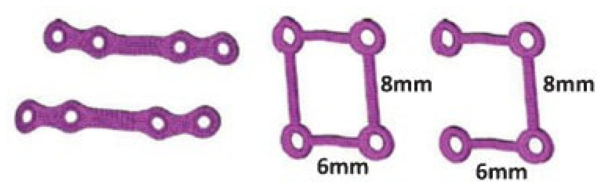
The 3D plate design that was introduced later by Farmand has two horizontal struts connected by vertical struts simu- lating the ideal requirement of plate according to Champy in the interforaminal region. The basic concept of three-dimen- sional (3D) fixation is “a geometrically closed quadrangular plate secured with bone screws creates stability in three dimensions” [
3] (p. 40).
Finite element analysis can be used to simulate the in vivo conditions for testing these designs in vitro as stress analysis helps us to analyze how hardware behaves within cortical and cancellous bone under masticatory load [
4].
We sought to propose an ideal plating design for fractures running through the mental foramen by comparing three plating designs: two four-hole miniplates, 2 × 2-hole 3D plates, and modified a 2 × 2-hole 3D plate with the posterior strut removed.
Materials and Methods
Data of the mandible from a healthy 25-year-old man with complete dentition were acquired using a light speed volume- computed multislice scanner (General Electric (GE) Healthcare, Cleveland, OH) with a slice thickness of 0.625 mm in Digital imaging for Communications in Medicine (DICOM) format further imported into Mimics 8.11 (Materialise, Leuven, Flemish Brabant) to convert the scans into a 3D Initial Graphics Exchange Specification (IGES) format for importation into any finite element analysis (FEA) or computer-aided design (CAD) program. The model was meshed using the Hypermesh 9.0 software (Altair Engineering, Troy, MI) (
Figure 1).
The dimensions of the miniplates, 3D plates, and screws were obtained from Stryker (Leibinger, Freiburg, Baden-Wurttemberg, Germany) (
Figure 2). The thicknesses of the miniplate and 3D plates were modeled as 1 mm and 0.6 mm, respectively, as obtained from Stryker. These physical models of the implants were converted into 3D CAD models using Solid- Works 2005 (Dassault systemes, Velizy-Villacoublay, Paris), which was also meshed using Hypermesh 9.0.
The meshed mandible with the plates and screws in this study consisted of approximately one lakh nodes and six lakhs elements. Finite element analysis and postprocessing of the results was done in ANSYS 12.1 (Analysis Systems Inc., Redondo Beach, CA). All the materials in this study have been modeled as elastic and isotropic.
The inputs for this finite element study consisted of the properties of the plate and the mandible and the shape of the fracture. The fracture line was designed as passing through the mental foramen to simulate such a clinical situation with the line angulated 15 degrees to the occlusal plane and the buccal plate. An interfragmentary gap of 0.05 mm mimicked the fracture.
The results from the two test conditions are compared by the amount of Von Mises stresses generated around the plates and bone and to study the mobility that is generated between the fracture fragments.
Material Properties
The material properties of mandible and the plates and screws were given to the model (
Table 1).
Boundary Condition
The boundary condition in the test is restriction of movement in all directions during mastication at both the condyles. The clinical scenario simulated is a molar clench ipsilateral to the fracture. All the models were tested for stability in two ways. In the first test, the bite force is simulated by restraining the condyles from displacement in all directions at the point of contact of the bite and then applying muscle force vectors. The mandible is subjected to forces produced by the muscles of mastication and by the reaction forces acting through the teeth and the temporomandibular joints (
Figure 3).
Table 2 gives the 3D muscular force vectors that defined the muscle attachment directions [
5,
6].
In the second test, a bite force of 500 N was applied on the premolar and molar region ipsilateral to the fracture after the condyles were restricted from movement in all directions (
Figure 4).
Results
For performance comparisons, Von Mises stresses and the gap distance or separation of the fracture fragments were chosen.
Von Mises Stress
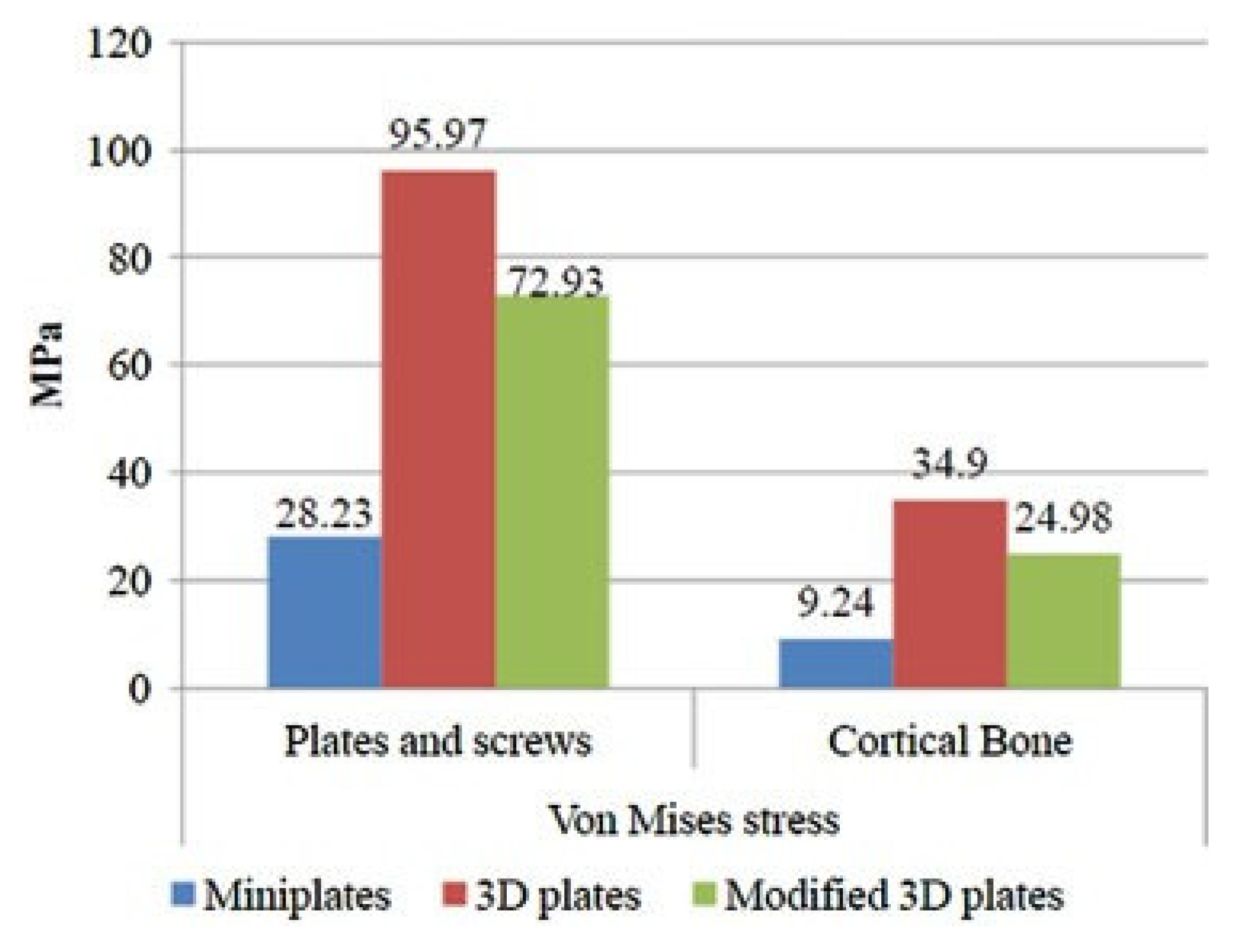
Von Mises stresses were measured, both in the bone and in the hardware. Figure 8 gives the comparative data of the measurements among the three models when tested by first method. Figure 10 gives the comparative data of the same measurements when tested by the second method.
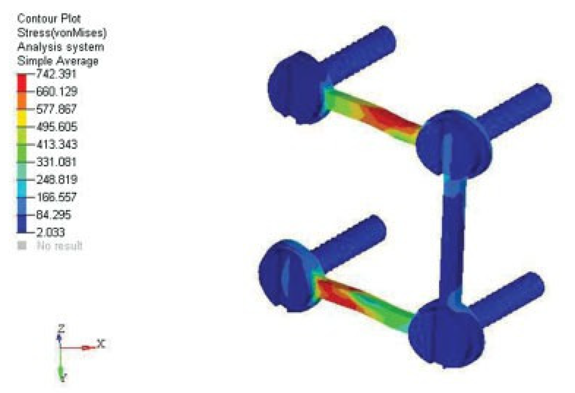
In the first test, the stress in the bone in the model plated with modified 3D plates was approximately three times more than the stress observed with miniplates but less when compared with the model that was plated with unmodified 3D plates. The stress observed in the model plated with unmodified 3D plates when compared with the miniplates was approximately four times more. Nevertheless in all the three models the stresses did not exceed the ultimate yield strength of bone. The stresses observed in the plates and screws in modified and unmodified 3D plate configuration were almost similar in magnitude and approximately three times greater than that observed in the miniplates, but they did not exceed the static yield limit of titanium (
Figure 5).
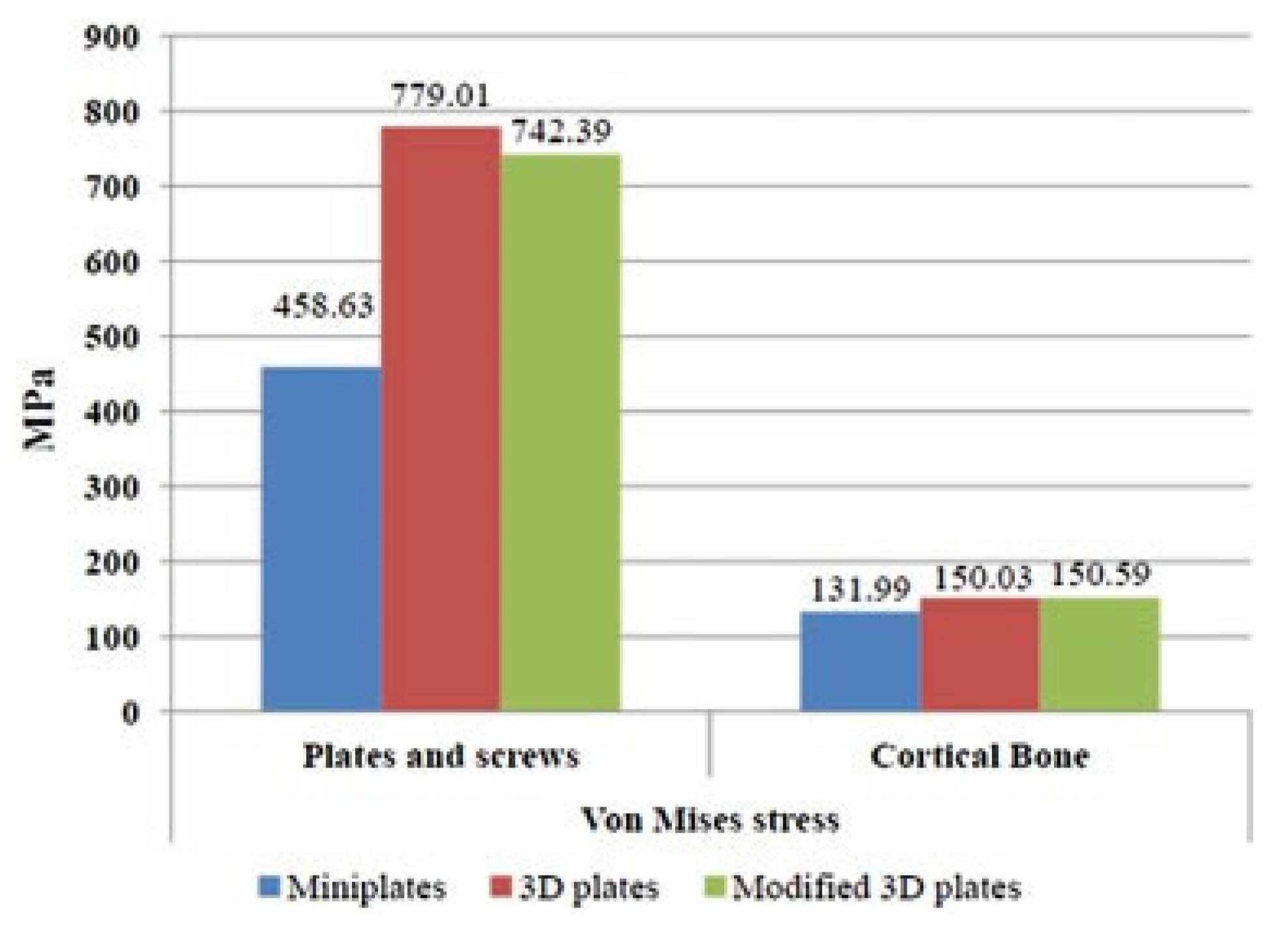
In the second test, the stresses were almost in the same range in all the three models and did not exceed the yield strength of bone. The stresses on the plates and screws did not exceed the yield limit of titanium in all the three categories (
Figure 6).
Gap or Fracture Mobility
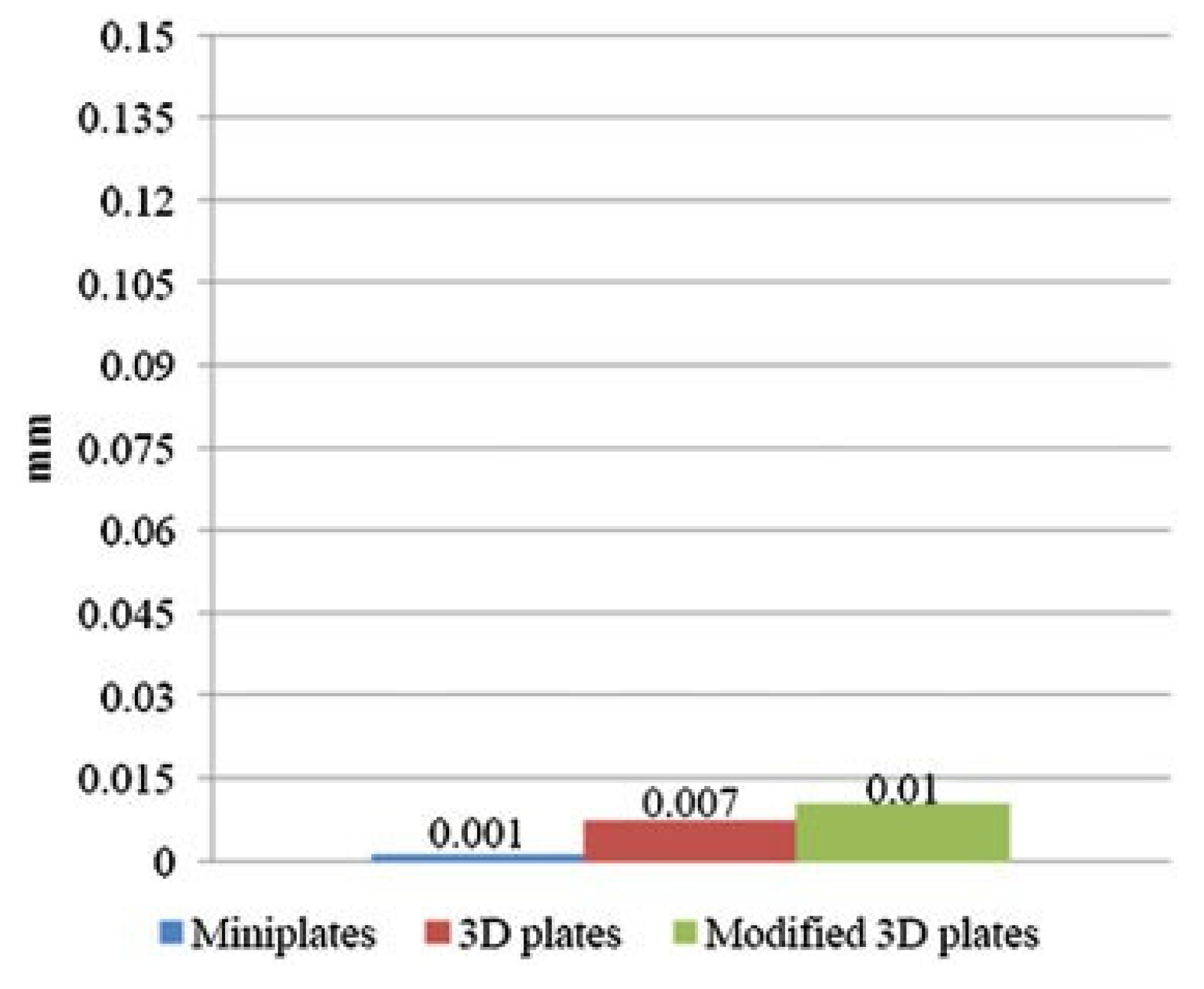
We measured gap or fraction mobility because it indicates the stability or rigidity of the fixed bone fragments. Figure 9 gives the comparative data of this measurement among the three models when tested by the first method. Figure 11 gives the comparative data of the same when tested by the second method.
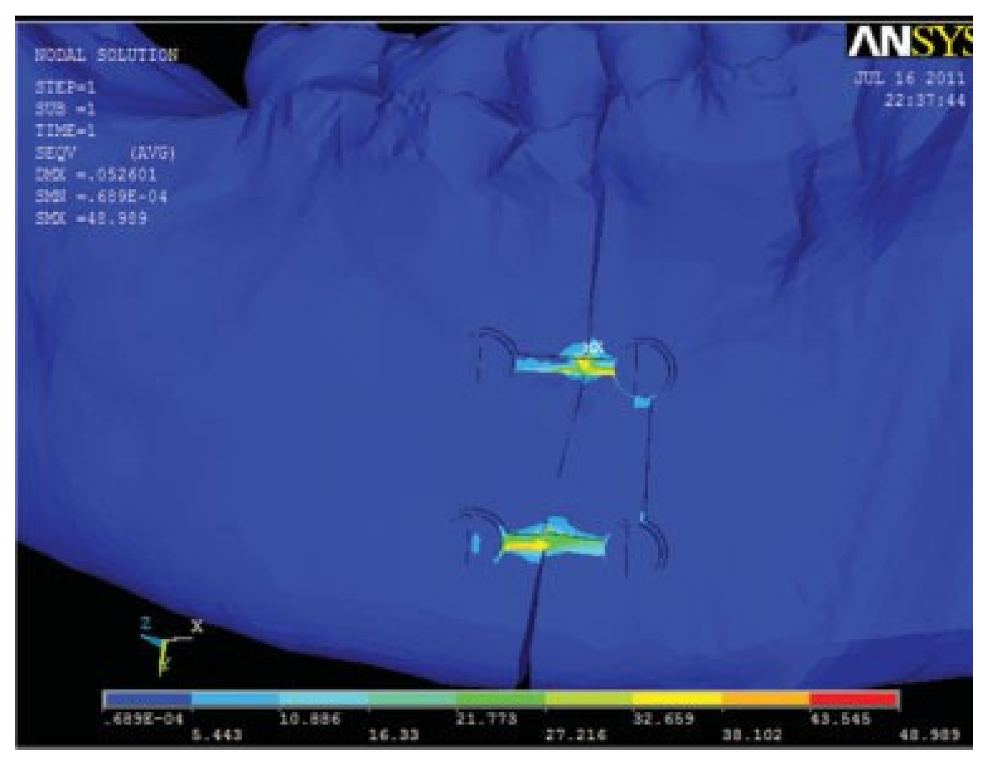
In the first test, the mobility in the model plated with modified 3D plates was ten times greater than that observed in the other two models. The calculated mobility in all the three models did not exceed 0.15 mm. The amount of mobility between the fracture fragments in model 3 in the first test is shown in
Figure 7. In the second test, in all three models the mobility was almost in the same range and did not exceed the designated 0.15 mm.
Figure 7.
Amount of mobility between the fracture fragments in model 3 in the first test. Scale factor in this picture is 144×.
Figure 7.
Amount of mobility between the fracture fragments in model 3 in the first test. Scale factor in this picture is 144×.
Figure 8.
Von Mises stress comparison between the three models in the first test.
Figure 8.
Von Mises stress comparison between the three models in the first test.
Figure 9.
Fracture mobility comparison between the three models in the first test.
Figure 9.
Fracture mobility comparison between the three models in the first test.
Figure 10.
Von Mises stress comparison between the three models in the second test.
Figure 10.
Von Mises stress comparison between the three models in the second test.
Figure 11.
Fracture mobility comparison between the three models in the second test.
Figure 11.
Fracture mobility comparison between the three models in the second test.
Discussion
The mandible is a complex anatomical structure with a composite makeup of cortical and cancellous structure with teeth embedded. The different forces acting at the muscles of mastication allow movement. The U-shaped bone has varied grain pattern that makes it difficult to be modeled. The use of 3D computerized tomographic data in DICOM for importation into any FEA program enables this modeling to be done at an accurate level.
Four things influence the accuracy of the finite element model: (1) geometric detail of the object to be modeled; (2.) the material properties; (3) the choice of the element type and number of nodes used; (4) the applied boundary conditions [
4]. In this study only the properties of dentin were modeled due to its high modulus of elasticity. The effect of dental pulp and cementum can be assumed to be negligible for stress analysis [
4]. The supraomohyoid muscles were also not included in the study as their influence in simulating the current clinical situation is negligent [
8]. The accuracy of FEA is influenced by the type and number of elements used. Increasing the number of elements in constructing the model will give us more details. The model in this study consisted of approximately one lakh nodes and six lakhs elements, which are quite satisfactory for any finite element study [
9]. In this study, the complex working of the temporomandibular joints were not considered as the condyles will be centered in their respective glenoid fossa during the unilateral molar clench [
10,
11].
Von Mises Stress
Von Mises stress is a representation of the general effective stress in a material and hence it was chosen [
12]. The maximum stress for cortical bone in tensile testing ranges from 92 to 188 MPa [
4], and the yield limit of that of titanium is found to be ~1000 MPa [
7]. Von Mises stress generated in the cortical bone surrounding the screws is an important measure because stresses beyond the ultimate strength of cortical bone can lead to loosening of the hardware and can cause screw pullout.
Gap Distance or Fracture Mobility
The upper limit of relative movement of the fragments was kept at 150 μm (0.15 mm) [
4]. When interfragmentary motion exceeds this range, nonunion can result. This was an in vitro study having all the limitations that are inherent in any in vitro study. An exact clinical situation cannot be simulated because of the impossibility of modeling such a finite element model.
Conclusion
In both the tests, the miniplates generated the least amount of stresses on the bone, plates, and screws and also generated the least amount of mobility along the fracture fragments, though the unmodified and the 3D plates also withstood all the stresses. The modified 3D plate showed less stress and fracture mobility than the unmodified 3D plate. But the difference between the two is not statistically significant, concluding that the modified 3D plate is equally efficient as its unmodified counterpart. Thus the removal of one vertical strut (posterior) in a 3D plate does not change the stability of the plate, and the modified 3D plates present a novel alternative to miniplates in the mental foramen region. An unmodified 3D plate cannot be used in the region because of the intervening mental nerve.
According to the Roux principle, “Maximum strength in the bone is to be achieved with a minimum quantity of the material” [
13] (p. 1834). The modified 3D plate provides relatively less hardware and achieves the required criteria to be an adequate method of immobilizing the bone fragments for osteosynthesis. Further study on clinical use and ease of handling and adaptability will shed light on this design of 3D plate.


