Next Article in Journal
Revision Surgery with Refixation After Mandibular Fractures
Previous Article in Journal
Patterns of Midface and Mandible Fractures in a Government Hospital
 
 
Craniomaxillofacial Trauma & Reconstruction is published by MDPI from Volume 18 Issue 1 (2025). Previous articles were published by another publisher in Open Access under a CC-BY (or CC-BY-NC-ND) licence, and they are hosted by MDPI on mdpi.com as a courtesy and upon agreement with Sage.
Article

Improving Cranial Vault Remodeling for Unilateral Coronal Craniosynostosis—Introducing Automated Surgical Planning

by
Emilie Robertson
1,2,*,
Pierre Boulanger
3,
Peter Kwan
1,
Gorman Louie
1 and
Daniel Aalto
2,4
1
Division of Plastic Surgery, University of Alberta, 8440 112 Street, Edmonton, AB T6G 2B7, Canada
2
Institute for Reconstructive Sciences in Medicine, Misericordia Hospital, Edmonton, AB, Canada
3
Department of Computing Sciences, University of Alberta, Edmonton, AB, Canada
4
Department of Rehabilitation Sciences, Division of Communication Sciences and Disorders, University of Alberta, Edmonton, AB, Canada
*
Author to whom correspondence should be addressed.
Craniomaxillofac. Trauma Reconstr. 2024, 17(3), 203-213; https://doi.org/10.1177/19433875231178912
Submission received: 1 November 2022 / Revised: 1 December 2022 / Accepted: 1 January 2023 / Published: 16 June 2023

Abstract

:
Study Design: Cranial vault remodeling (CVR) for unicoronal synostosis is challenging due to the asymmetric nature of the deformity. Computer-automated surgical planning has demonstrated success in reducing the subjectivity of decision making in CVR in symmetric subtypes. This proof of concept study presents a novel method using Boolean functions and image registration to automatically suggest surgical steps in asymmetric craniosynostosis. Objective: The objective of this study is to introduce automated surgical planning into a CVR virtual workflow for an asymmetric craniosynostosis subtype. Methods: Virtual workflows were developed using Geomagic Freeform Plus software. Hausdorff distances and color maps were used to compare reconstruction models to the preoperative model and a control skull. Reconstruction models were rated as high or low performing based on similarity to the normal skull and the amount of advancement of the frontal bone (FB) and supra-orbital bar (SOB). Fifteen partially and fully automated workflow iterations were carried out. Results: FB and SOB advancement ranged from 3.08 to 10.48 mm, and −1.75 to 7.78 mm, respectively. Regarding distance from a normal skull, models ranged from .85 to 5.49 mm at the FB and 5.40 to 10.84 mm at the SOB. An advancement of 8.43 mm at the FB and 7.73 mm at the SOB was achieved in the highest performing model, and it differed to a comparative normal skull by .02 mm at the FB and .48 mm at the SOB. Conclusions: This is the first known attempt at developing an automated virtual surgical workflow for CVR in asymmetric craniosynostosis. Key regions of interest were outlined using Boolean operations, and surgical steps were suggested using image registration. These techniques improved post-operative skull morphology

Background

Craniosynostosis is a relatively common birth defect affecting up to 1 in 1000 children. Left untreated, craniosynostosis can affect normal brain growth and development, can cause visual impairment, and can have a significant psychosocial impact on the child [1]. Unicoronal synostosis (UCS) is a common subtype of craniosynostosis that is especially difficult to treat due to the asymmetrical nature of the deformity. Cranial vault reconstruction (CVR) is a primary method to surgically correct UCS, where the goals of surgery are to expand the intracranial volume, reduce the risk of abnormal brain growth, and to normalize head shape and appearance [2].
The use of virtual surgical planning (VSP) has been increasing for craniosynostosis reconstruction. VSP has been shown to reduce intra-operative procedure length [3,4,5]. Virtual technologies have demonstrated particular utility for complex craniofacial cases [6,7]. Time spent deciding where to make osteotomies and in what configuration to plate bone segments is shifted from the operating room to the preplanning virtual environment. Efforts using VSP in CVR have used normal skulls as a template to guide surgical osteotomies and plating [8,9,10]. Having a reference skull reduces the subjectivity of surgical decision making. While studies have produced aesthetic results using this technique, planning times and cost are prohibitive to its use, limiting this technology to few tertiary centers [7,11]. Introducing automation in virtual planning is an attractive option to reduce the guesswork in surgical decision making, and to improve time and cost efficiency. Objectivity and accessibility are key design criteria in the development of a CVR workflow. Minimizing surgeon involvement in the surgical decisionmaking process reduces the degree of guesswork. A method for automatic CVR planning that meets these design elements may increase the availability of advanced technologies in the surgical planning environment.
Preliminary attempts at automating this process have demonstrated success in a symmetrical craniosynostosis phenotype [12,13,14]. Porras et al [12] introduced a transformation model that automatically generated a surgical plan for fronto-orbital advancement (FOA) in metopic craniosynostosis in 4 hours. The algorithm was improved to include overcorrection and planning times reduced to under 30 seconds [15]. Expert surgeons agreed on the usefulness of the proposed computer-generated surgical plans. The workflow does not allow for bone exchange, limiting its use to the correction of metopic craniosynostosis. The workflow utilizes the software CranioPlan which is available on an open source platform and requires a moderate degree of computer literacy to navigate.
Using computer algorithms to generate surgical plans has the potential to reduce the subjectivity, planning duration, and cost of virtual surgical planning. Previous methods of achieving this are mathematically advanced and have not been applied to asymmetric craniosynostosis. The first objective of this study was to develop a manual virtual surgical workflow for an FOA for UCS using the in-house software at the study institution. The second objective was to automate components of the workflow to reduce surgeon involvement in the planning process, creating a partially automated workflow. The overall goal was to build the conceptual framework for the development of a fully automated computer algorithm for UCS surgery.

Methods

The University of Alberta ethics institution review board approved this study (Pro00085524). An iterative design process was used to develop virtual workflows in this study using Geomagic Freeform Plus software (Version 2017). In-house workflow development adhered to the accessibility and cost-effective design criteria as the costs of outsourcing development were avoided. Based on available imaging, a three-month-old female with right-sided UCS and an age- and sex-matched normal skull were used as the index case pair in this single case feasibility study. In part 1, the initial virtual workflow was developed and did not include automated components. This “manual workflow” served as the template, into which automated steps were introduced in part 2. This study represents the first attempt at virtual planning using in-house software for CVR at the study institution, and therefore the manual workflow was a necessary first step in the development of an automated workflow.

Part I: Manual Workflow

CT scans were retrieved using a local radiology database after ethics review board approval (Pro85524). The UCS skull and matched normal skull were registered using a previously published workflow [16], and the corresponding stereolithography (STL) files were imported into Geomagic Freeform Plus (3D Systems, Rock Hill, South Carolina, USA). Key steps in the manual workflow are isolating the frontal bones (FBs) and supraorbital bar (SOB) regions of interest (ROI) and manipulating them to approximate a normal head shape. This software allows bending, rotation, and translation of isolated bone segments. The manual workflow steps are outlined in Figure 1. This represents an example of an FOA using the patient’s existing frontal bones to create the neo-forehead—a method commonly employed at the study institution. Input from a pediatric craniomaxillofacial surgeon was obtained throughout development to assess the fidelity of the virtual surgical workflow.
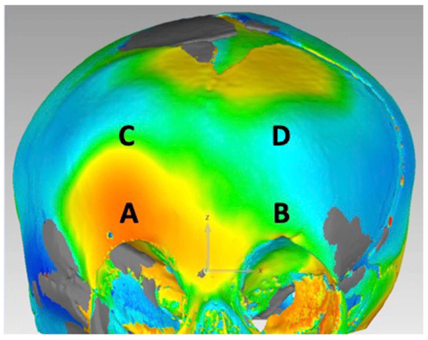
The reconstruction model using the manual VSP workflow was analyzed using Geomagic Control (Version 2015.3.1.0). Maximum Hausdorff surface distances were calculated at 4 points along the frontal bones and supraorbital bar and compared to the control skull model (Figure 2). The root mean squared error (RMSE) of the maximum surface distances at each point was calculated. The same calculations were made for the pre-operative skull model. A smaller RMSE represents a model that is closer shape to a normal reference skull and therefore a successful reconstruction. In addition, color maps were generated in Geomagic Control to qualitatively assess the improvement in skull morphology at the frontal bones and superior orbital bar.

Part II: Automated Workflow

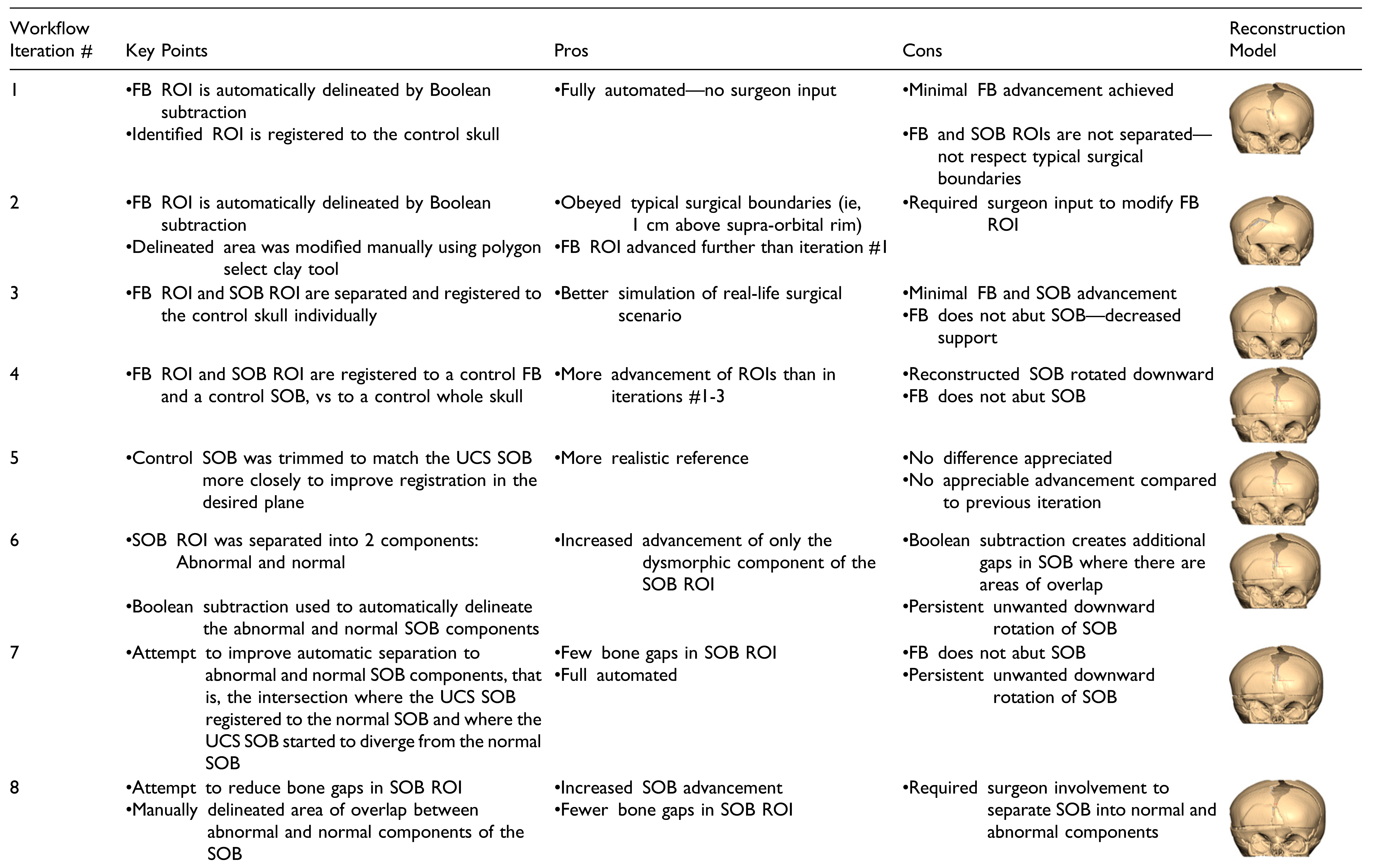
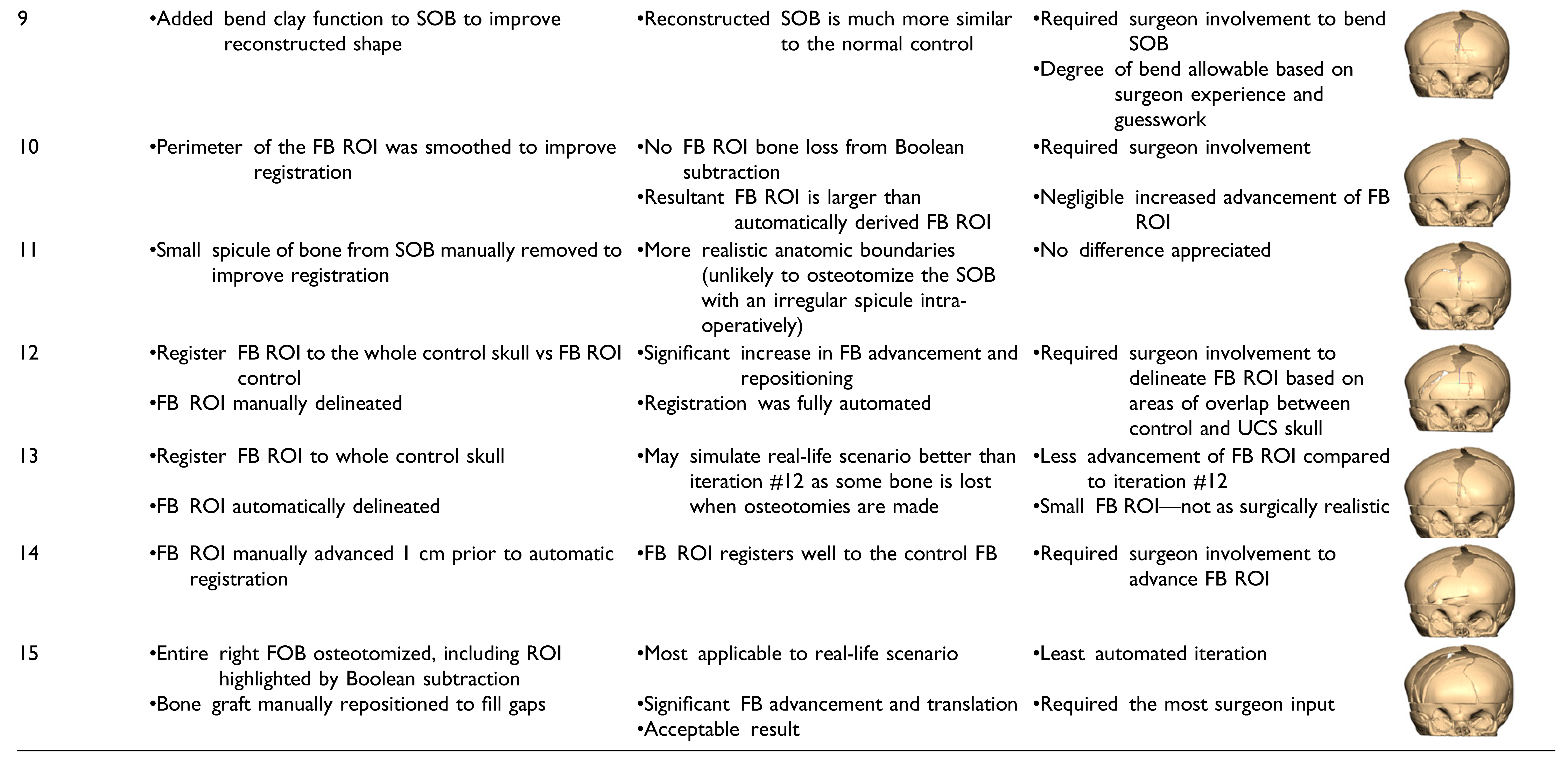
Fifteen iterations of a partially automated workflow were carried out. Automated steps were introduced into the manual workflow by using techniques such as Boolean operations on polygons and object registration. All the fifteen automated workflow it-erations varied in the surgeon involvement required. There are iterations that follow a rigid algorithm design requiring zero input from the surgeon, and others that follow a semi-rigid paradigm and require a degree of surgeon guidance in the planning degree of process. The key changes, pros, and cons of each iteration are summarized in Table 1.
To assess the amount of advancement of the SOB and FB using the partially automated workflows, Hausdorff surface distances were automatically calculated in 3D Slicer (Version 10.2) between the reconstruction models and the pre-operative UCS skull. The same method was used to calculate distances between the reconstruction models and the normal control skull, to assess the similarity between the reconstruction model and normal skull morphology. Skulls that had a large surface distance value in comparison to the pre-operative skull and small surface distance values in comparison to the normal skull were considered successful reconstructions. In addition, color maps for all skull reconstruction models were generated using the Shape Population Viewer module to qualitatively assess the skull morphology.

Regions of Interest

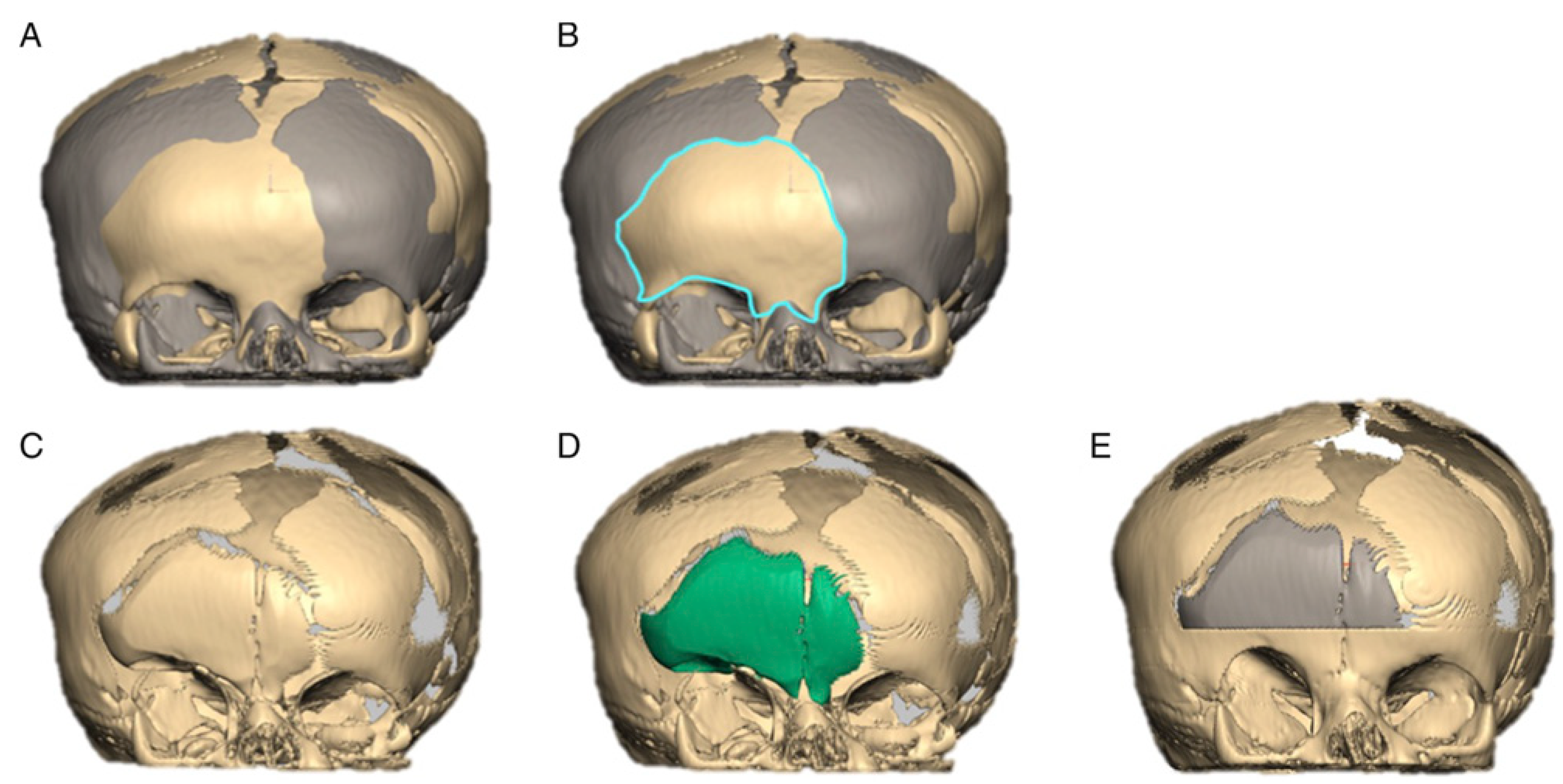
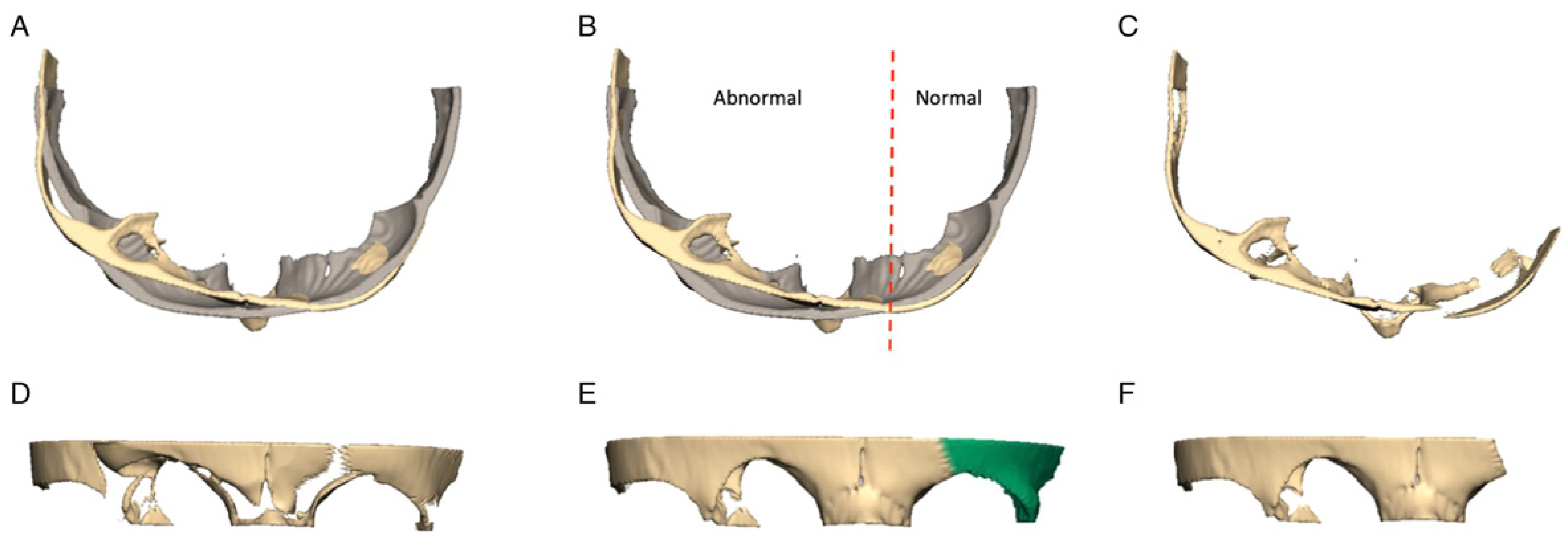
The key concept behind introducing automation into the virtual workflow for FOA is the use of Boolean functions and registration of key ROIs to reshape a UCS skull. The ROIs for an FOA are the SOB and the frontal bones (FBs). A Boolean subtraction function was used in this study by taking advantage of the fact that a UCS skull and a normal skull that are registered to each other will overlap in areas of less deformity. Intuitively, areas of the UCS skull that are less dysmorphic will line up well with a normal skull reference. On the other hand, in areas like the flattened frontal bone on the synostotic side of the UCS skull, the skulls will only overlap in areas surrounding the dysmorphic bone, forming a perimeter around the area of flattening. This perimeter is used to automatically delineate the area that requires surgical advancement. An example of how a Boolean subtraction function was used to automate the identification of a frontal bone ROI is shown in Figure 3. Once identified, this piece is registered to the control skull to determine its optimal position. The registration function in Freeform Plus (Version 2017) automatically positions an ROI in relation to the reference skull by minimizing the surface distances between each model. The piece is automatically translated and rotated in all planes to find the best fit to the normal skull. The same Boolean subtraction function can be applied to the SOB ROI—automatically highlighting the portion that requires advancement and reshaping and to what degree (Figure 4).

Results

Part I: Manual Workflow

The RMSE of the maximum surface distance values for the pre-operative UCS skull was 3.3 mm, and the value for the model reconstructed using the manual virtual workflow was smaller at 1.4 mm (Table 2). Color maps demonstrated that the reconstructed forehead was also more symmetrical than pre-operatively. This demonstrated that it was possible to virtually improve the forehead shape in a UCS skull using the stepwise virtual design outlined in Figure 1.

Part II: Automated Workflow

The results for the amount of advancement achieved in the 15 reconstruction models compared to the preoperative UCS skull model are listed in Table 3. The model with the largest surface distance compared to the preoperative model at the FB was #14, with advancement of 10.5 mm. The model with the largest surface distance compared to the pre-operative model at the SOB was #11, with a maximum advancement of 7.9 mm. The models that achieved the smallest degree of advancement for the FB and SOB were #11 (3.1 mm) and #3 (−1.8 mm), respectively.
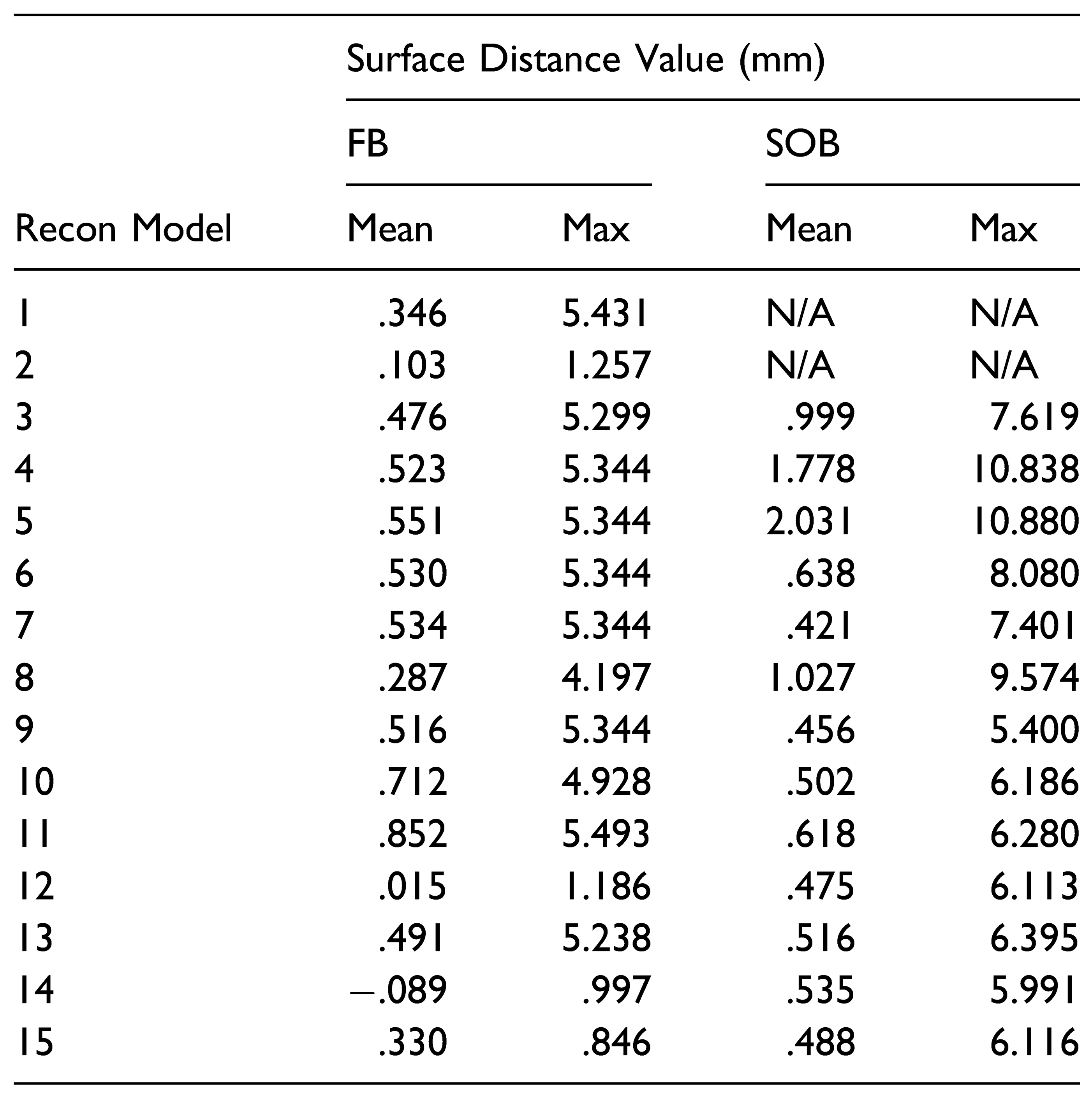
The results for the 15 reconstruction models compared to the control skull model are listed in Table 4. For the normal skull comparison, how close the overall shape approximates a normal skull is important and therefore the average surface distance values were also reported. For the maximum degree of surgical advancement, only the maximum surface distance values are reported.
The reconstruction models with the smallest mean surface distances compared to a control skull at the FB were #12 (.015 mm), #14 (−.089 mm), and #2 (.103 mm). The reconstruction models with the smallest mean surface distances compared to a control skull at the SOB were #7 (.421 mm), #9 (.456 mm), and #12 (.475 mm). These models achieved the closest FB and SOB shape to a control skull.
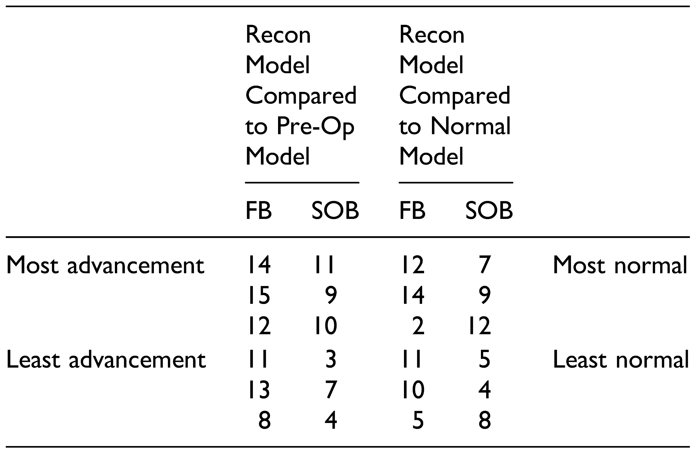
Model #12 was the highest overall performer, and models #5 and #8 were the lowest overall performers. Model #12 was the only model that achieved advancement and normality in both ROIs, whereas models #5 and #8 achieved poor advancement and poor normality in both ROIs (Table 5).

Discussion

An in-house manual VSP workflow was developed using Geomagic Freeform Plus. The workflow was used to simulate an FOA in a three-month-old female with UCS. The skull model reconstructed using the workflow had a forehead that was closer in shape to a normal skull, demonstrated by smaller RMSE values, and was more symmetrical based on a qualitative color map assessment. The benefit of the manual workflow is that a surgical team can simulate an operation multiple times virtually without any consequence to the patient. The downsides are that all the steps are still dictated by subjective decisions made by a surgeon or surgical designer. This guesswork has been attributed to unreliable results and a large variation between surgeons regarding reconstruction outcomes in CVR [11]. To reduce this subjectivity, Boolean operations on polygons and 3D model registration were introduced to create a partially automated workflow for an FOA procedure that had a reduced the need for surgeon involvement to guide the planning process.
Boolean operations on polygons are popular methods for designing solid objects. Typically primitive shapes are introduced, and new objects and 3D models can be created by using the 3 types of Boolean functions: union, subtraction, and intersection [17]. Boolean operations have been used previously in VSP, particularly for a surgical guide and splint design [18,19,20,21]. Similar to this study, Wang et al [22] used Boolean subtraction to outline the surgical region of interest to create an aesthetically pleasing toe-to-thumb transfer. This is the first study that uses Boolean operations to outline surgical ROIs in virtual cranial vault remodeling. A subtraction function worked well to identify the frontal bone area requiring advancement. This might be of particular benefit in surgical planning when deciding whether to perform a unilateral vs a bilateral FOA. If the frontal bone ROI did not cross midline, the argument could be made to attempt a unilateral FOA.
The same automation techniques were applied to the SOB. However, the results were less consistent and of limited utility. The superior and inferior rotation of the SOB was not controlled in the automated workflow when registering it to a normal reference. As a result, a large distance could refer to a large downward rotation, limited anterior translation, and therefore not correlate to a clinically improved SOB. Limiting planes of motion for specific surgical maneuvers such as SOB advancement for a virtual FOA would be an important component of an automated workflow.
Iterations of the automated workflow that followed a partially automated paradigm produced better results. Fully automated iterations produced reconstruction models that had a suboptimal forehead shape and did not simulate typical surgical boundaries, such as the cranial edge of the supra-orbital bar. However, several iterations that resulted in successfully advanced ROIs and improved forehead shape had a combination of manual and automated steps. In iteration #15, for example, the FB ROI was automatically outlined using a Boolean operation. Then, the FB osteotomy was manually designed to incorporate this area but adhered to a triangular configuration that mimics how frontal bones are typically osteotomized at the study institution. The result was a reconstruction model that had significant advancement of the ROIs and approximated a normal skull shape, while suggesting steps that are surgically realistic. This contrasts with iteration #12 that produced a high performing model based on the outlined criteria. While the reconstruction model in this iteration produced a skull that approximated a normal reference and achieved a large degree of advancement of the ROIs, the design of the osteotomy would likely result in noticeable contour abnormalities on the patient’s forehead. The benefits of a procedure like the one described for iteration #15 are that the surgeon has additional control over the design of the osteotomy with the benefit of automatically derived suggestions on where to position the bone fragments. This highlights the important concept that automated surgical planning can successfully reduce the subjectivity of surgical decision making and result in reconstruction models that are mathematically superior to the preoperative models. However, clinician input is still crucial to refine a plan and ensure its feasibility. In addition, involvement in the planning process is an important component of surgical training. Computer automation can be viewed as a helpful adjunct to traditional surgeonbased planning. Using automation to reduce the guesswork in surgical planning in conjunction with human input may increase the uptake of new technology, especially in initial phases. Even in highly sophisticated computation models, there are steps that require human input [14].
The presented workflows can be carried out using fundamental computing functions that are widely available in many software programs. In addition, these functions are easily automated, and the demonstration of their potential in surgical planning is optimistic for the development of a fully automated planning algorithm. The workflow uses comparative normal skulls as the reference model, a resource that most institutions have access to. While statistical shape models allow for accurate registration and analysis, their development requires expertise in medical imaging and analysis [23]. Although there are downsides to a simplified approach to automating surgical planning, it affords a degree of flexibility that can be applied to surgical planning for asymmetric craniosynostosis. Automatically outlining ROIs has the potential to reduce the guesswork associated with CVR and may be valuable to surgical teams.
The automatic delineation of an ROI can have a number of applications. This information can be used simply to refine or confirm a pre-determined surgical FOA plan. It can also be used to virtually plan an entire operation. In the latter scenario, it would be possible to print surgical cutting and plating guides to translate the virtual plan to the operating room with increased precision—a technique that has demonstrated to be beneficial [3,4,5,6,7,8,9,10,11].

Limitations

There are limitations of the presented workflows. Firstly, proprietary software was used and may be a deterrent to their widespread use. However, Boolean operations are common and available in open-source software programs, such as 3D Slicer (Version 4.10.2). It is possible that the concept can be applied in programs that are more accessible.
There is also no biomechanical information regarding the properties of infant bone in either the manual or automated orkflow. The challenge of introducing bone bending in automated CVR algorithms has only recently been introduced [14]. In the proposed workflow, the degree to which bones can bend before fracturing is based on visual judgment and surgeon experience. Additional components key to the planning process for an FOA, such as bone growth and the potential for relapse, also rely on surgeon’s judgment and are not automated in the outlined paradigm.
One limitation with pre-operative imaging in infants relates to the rapid growth of the craniofacial skeleton at this age. Due to this, imaging used for surgical planning should ideally be obtained within 1 month of surgery to best match the size of the calvarium at the time of surgery.
Lastly, the automated workflow relies on the successful registration of a UCS and a normal skull. Using age- and sex-matched skulls to achieve this has been done frequently with success [11,24,25]. This relies on the availability of a library of normal skull CT scans. Some institutions may not have such a repository of CT information available, or some skulls may be difficult to match for other reasons such as the degree of deformity. In these circumstances, the presented workflow may be of limited use. One method to improve the registration accuracy in these scenarios would be to use statistical shape modeling as opposed to matched skulls [26,27].

Conclusions

This study presents a conceptual basis and pilot data for an alternative method to develop automated surgical workflow algorithms for cranial vault remodeling. This is the first study to use Boolean operations on polygons and registration to suggest surgical steps for cranial vault remodeling. It is also the first known attempt at automating surgery for an asymmetric craniosynostosis subtype. The automated workflow has the potential to reduce the guesswork involved in surgical decision making for cranial vault remodeling by highlighting key regions of interest in an infant skull and suggesting possible reconstruction models. The benefit of the proposed workflow lies in its simplicity— employing techniques that are simple to understand, use, and are widely available through various software programs. A simple approach to automated surgical planning has limitations but may result in more clinician uptake than more sophisticated methods.

Funding

The author(s) disclosed receipt of the following financial support for the research, authorship, and/or publication of this article: This work was supported by the Covenant Health Research Center Seed Grant [#13949].

Authors’ Notes

Presented virtually at Canadian Society of Plastic Surgeons (CSPS) Annual Meeting 2021.

Declaration of Conflicting Interests

The author(s) declared no potential conflicts of interest with respect to the research, authorship, and/or publication of this article.

References

  1. Tahiri, Y.; Bartlett, S.P.; Gilardino, M.S. Evidence-based medicine: Nonsyndromic craniosynostosis. Plast Reconstr Surg. 2017, 140(1), 177e–191e. [Google Scholar] [CrossRef] [PubMed]
  2. Alford, J.; Derderian, C.A.; Smartt, J.M. Surgical Treatment of Nonsyndromic Unicoronal Craniosynostosis. J Craniofac Surg. 2018, 29(5), 1199–1207. [Google Scholar] [CrossRef] [PubMed]
  3. Khechoyan, D.Y.; Saber, N.R.; Burge, J.; et al. Surgical outcomes in craniosynostosis reconstruction: The use of prefabricated templates in cranial vault remodelling. J Plast Reconstr Aesthet Surg. 2014, 67(1), 9–16. [Google Scholar] [CrossRef] [PubMed]
  4. Msallem, B.; Beiglboeck, F.; Honigmann, P.; Jaquie´ry, C.; Thieringer, F. Craniofacial Reconstruction by a Cost-Efficient Template-Based Process Using 3D Printing. Plast Reconstr Surg Glob Open. 2017, 5(11), e1582. [Google Scholar] [CrossRef]
  5. Xia, J.J.; Phillips, C.V.; Gateno, J.; et al. Cost-effectiveness analysis for computer-aided surgical simulation in complex cranio-maxillofacial surgery. J Oral Maxillofac Surg. 2006, 64(12), 1780–1784. [Google Scholar] [CrossRef]
  6. Fisher, M.; Medina, M.; Bojovic, B.; Ahn, E.; Dorafshar, A. Indications for computer-aided design and manufacturing in congenital craniofacial reconstruction. Craniomaxillofac Trauma Reconstr. 2016, 9(03), 235–241. [Google Scholar] [CrossRef]
  7. LoPresti, M.; Daniels, B.; Buchanan, E.P.; Monson, L.; Lam, S. Virtual surgical planning and 3D printing in repeat calvarial vault reconstruction for craniosynostosis: technical note. J Neurosurg Pediatr. 2017, 19, 490–494, Published online April 2017. [Google Scholar] [CrossRef]
  8. Burge, J.; Saber, N.R.; Looi, T.; et al. Application of CAD/CAM prefabricated age-matched templates in cranio-orbital remodeling in craniosynostosis. J Craniofac Surg. 2011, 22(5), 1810–1813. [Google Scholar] [CrossRef]
  9. Delye, H.; Clijmans, T.; Mommaerts, M.Y.; Sloten, J.V.; Goffin, J. Creating a normative database of age-specific 3D geometrical data, bone density, and bone thickness of the developing skull: a pilot study. J Neurosurg Pediatr. 2015, 16, 687–702, Published online December. [Google Scholar] [CrossRef]
  10. Marcus, J.R.; Domeshek, L.F.; Loyd, A.M.; et al. Use of a threedimensional, normative database of pediatric craniofacial morphology for modern anthropometric analysis. Plast Reconstr Surg. 2009, 124(6), 2076–2084. [Google Scholar] [CrossRef]
  11. Soleman, J.; Thieringer, F.; Beinemann, J.; Kunz, C.; Guzman, R. Computer-assisted virtual planning and surgical template fabrication for frontoorbital advancement. Neurosurg Focus. 2015, 38, E5–E5. [Google Scholar] [CrossRef] [PubMed]
  12. Porras, A.R.; Zukic, D.; Equobahrie, A.; Rogers, G.F.; Linguraru, M.G. Personalized Optimal Planning for the Surgical Correction of Metopic Craniosynostosis. In Clinical Image-Based Procedures. Translational Research in Medical Imaging; Shekhar, R., Wesarg, S., González Ballester, M.Á., et al., Eds.; Springer International Publishing: New York, NY, USA, 2016; Volume 9958, pp. 60–67. [Google Scholar]
  13. Porras, A.R.; Paniagua, B.; Enquobahrie, A.; et al. Locally Affine Diffeomorphic Surface Registration for Planning of Metopic Craniosynostosis Surgery. In Medical Image Computing and Computer-Assisted Intervention—MICCAI 2017; Descoteaux, M., Maier-Hein, L., Franz, A., Jannin, P., Collins, D.L., Duchesne, S., Eds.; Springer International Publishing: New York, NY, USA, 2017; Volume 10434, pp. 479–487. [Google Scholar]
  14. Porras, A.R.; Paniagua, B.; Ensel, S.; et al. Locally affine diffeomorphic surface registration and its application to surgical planning of fronto-orbital advancement. IEEE Trans Med Imaging. 2018, 37(7), 1690–1700. [Google Scholar] [CrossRef] [PubMed]
  15. García-Mato, D.; Porras, A.R.; Ochandiano, S.; et al. Effectiveness of automatic planning of fronto-orbital advancement for the surgical correction of metopic craniosynostosis. Plast Reconstr Surg Glob Open. 2021, 9(11), e3937. [Google Scholar] [CrossRef] [PubMed]
  16. Robertson, E.; Kwan, P.; Louie, G.; Boulanger, P.; Aalto, D. Testretest validation of a cranial deformity index in unilateral coronal craniosynostosis. Computer Methods in Biomechanics and Biomedical Engineering 2020, 21, 1–13, Published online July. [Google Scholar] [CrossRef]
  17. Masuda, H. Topological operators and boolean operations for complex-based nonmanifold geometric models. Comput Aided Des. 1993, 25(2), 119–129. [Google Scholar] [CrossRef]
  18. Charton, J.; Laurentjoye, M.; Kim, Y. 3D Boolean operations in virtual surgical planning. Int J Comput Assist Radiol Surg. 2017, 12(10), 1697–1709. [Google Scholar] [CrossRef]
  19. Chen, X.; Li, X.; Xu, L.; Sun, Y.; Politis, C.; Egger, J. Development of a computer-aided design software for dental splint in orthognathic surgery. Sci Rep. 2016, 6(1), 38867. [Google Scholar] [CrossRef]
  20. Lin, Y.; Zhang, S.; Chen, X.; Wang, C.; Qu, Y.L.; Lu, X. A novel method in the design and fabrication of dental splints based on 3D simulation and rapid prototyping technology. Int J Adv Manuf Technol 2006, 28(9–10), 919–922. [Google Scholar] [CrossRef]
  21. Zhan, Q.; Chen, X. In: Zhang Q, ed. Boolean combinations of implicit functions for model clipping in computer-assisted surgical planning. PLoS One 2016, 11(1), e0145987. [Google Scholar] [CrossRef]
  22. Wang, L.; Tian, G.; Wang, M.; Yang, G. Analysis of the morphologic differences of the second toe and digits of the hand, and evaluation of potential surgical intervention to minimize the differences using computer-aided design technology. Plast Reconstr Surg. 2014, 134(6), 902e–912e. [Google Scholar] [CrossRef]
  23. Porras,, A.R.; Tu, L.; Tsering., D.; et al. Quantification of head shape from three-dimensional photography for presurgical and postsurgical evaluation of craniosynostosis. Plast Reconstr Surg 2019, 144(6), 1051e–1060e. [Google Scholar] [CrossRef] [PubMed]
  24. Chim, H.; Wetjen, N.; Mardini, S. Virtual surgical planning in craniofacial surgery. Semin Plast Surg. 2014, 28(03), 150–158. [Google Scholar] [CrossRef] [PubMed]
  25. Dangi, S.; Shah, H.; Porras, A.R.; et al. Robust head CT image registration pipeline for craniosynostosis skull correction surgery. Healthc Technol Lett. 2017, 4(5), 174–178. [Google Scholar] [CrossRef] [PubMed]
  26. Mendoza, C.S.; Safdar, N.; Okada, K.; Myers, E.; Rogers, G.F.; Linguraru, M.G. Personalized assessment of craniosynostosis via statistical shape modeling. Med Image Anal. 2014, 18(4), 635–646. [Google Scholar] [CrossRef]
  27. Saber, N.R.; Phillips, J.; Looi, T.; et al. Generation of normative pediatric skull models for use in cranial vault remodeling procedures. Childs Nerv Syst. 2012, 28(3), 405–410. [Google Scholar] [CrossRef]
Figure 1. Virtual workflow for a unilateral FOA procedure in a patient with UCS is shown. This is one example of how the bone components can be manipulated to approximate a normal head shape. A) An STL skull is imported into Geomagic Freeform Plus software. B) The SOB ROI is delineated. C) The FB ROI is delineated. D) The FB and SOB ROIs are isolated to allow their individual manipulation. E) The FB ROI is removed simulating the FB osteotomy. F) The SOB is removed simulating the SOB osteotomy. G) The SOB ROI is reshaped using a bending tool. H) The SOB ROI is repositioned on the skull. I) The FB ROIs are rotated and exchanged from left to right and vice versa. J) The virtual surgery is finished and the reconstructed skull model is complete.
Cmtr 17 00032 g001
Figure 2. Points A and B represent the right and left SOBs of the skull model, and points C and D represent the right and left frontal bones, respectively. These represent the 4 points where maximum Hausdorff surface distance measurements were taken to analyze the shape of the virtually reconstructed skull. The warm hues in the color map denote areas in the pre-operative skull model that were advanced more than areas in cooler hues. In the model below, it is clear that the right frontal bone on the synostotic side was advanced more than the left frontal bone, to achieve a more symmetric forehead shape.
Cmtr 17 00032 g002
Figure 3. A Boolean subtraction function can be used to automatically delineate the FB ROI in the UCS skull. In panel A, the grey skull is the UCS skull and the beige skull is the matched normal skull. The right frontal bone area on the UCS skull is not visible, due to the flattened and retropositioned frontal bones on the synostotic side. Panel B highlights the area in blue that is automatically calculated as the frontal bone ROI using a Boolean subtraction operation, taking advantage of intersecting areas between the 2 skulls. Panel C shows the UCS skull, now in beige, with the frontal bone ROI isolated. The normal skull model was subtracted from the UCS skull to highlight the region that is flattened in the UCS skull. Panel D shows the frontal bone ROI highlighted in green. Panel E demonstrates how the ROI can be modified to respect surgical boundaries and maintain a separate ROI for the supra-orbital bar.
Cmtr 17 00032 g003
Figure 4. A Boolean subtraction function can be used to automatically delineate the component of the SOB ROI in the UCS skull that requires reshaping and advancement. A) The UCS SOB (beige) and the control SOB (grey) are registered and shown from a bird’s eye view. B) The intersection between where the UCS and normal SOB overlap and begin to diverge is demonstrated. This is what will be automatically highlighted with the Boolean subtraction function. C) The control SOB is subtracted from the UCS SOB using a Boolean function. D) This image demonstrates the problematic resulting UCS SOB with the various areas of missing bone where areas overlapped. E) The “normal” part of the SOB ROI is highlighted in green and subtracted from the UCS SOB to reduce the amount of bone loss. F) Only the SOB component that requires advancement and reshaping is isolated.
Cmtr 17 00032 g004
Table 1. A summary of the iterative design process is outlined. Key points, pros, and cons of the changes introduced in each iteration are explained.
Cmtr 17 00032 i001aCmtr 17 00032 i001b
Table 2. Summary of maximum Hausdorff surface distances between the pre-operative UCS skull model and a control skull, and the post-operative reconstruction UCS model and a control skull. A negative value indicates a skull point on the UCS model that is positioned more posterior than the control skull.
Cmtr 17 00032 i002
Table 3. Maximum surface distance values between the FB and SOB of the reconstruction UCS model compared to the preoperative UCS model.
Cmtr 17 00032 i003
Table 4. Maximum and mean surface distance values between the FB and SOB of the reconstruction UCS model compared to the control skull model.
Cmtr 17 00032 i004
Table 5. Highest- and the lowest-performing moÞls are presented. Overall high performance was determined by highest degree of advancement and/or high degree of normalcy in both ROIs. Overall low performance was determined by lowest degree of advancement and/or low degree of normalcy in both ROIs.
Cmtr 17 00032 i005