Abstract
The carotid-cavernous fistula (CCF) is a rare complication in patients victimized by craniofacial trauma. It involves multidisciplinary medical action. Owing to its potential complications, it is essential that maxillofacial surgery and neurosurgery specialists diagnose this condition so that appropriate treatment can be performed. The authors present a report of a case 11 years after the surgery.
Carotid-cavernous fistula (CCF) is a rare condition [1] and may occur spontaneously or, more frequently, in patients victimized by craniofacial or merely facial trauma (75% of cases) [2].
Hunter [1], in 1757, was the first physician to report the arteriovenous fistula. Benjamin Travers, in 1809, described the first case of unilateral pulsatile exophthalmos, probably resulting from a CCF [1,3].
This condition may appear in a way that simulates conjunctivitis, unilateral glaucoma, or even Graves disease.4
CCF occurs due to abnormal communication between the carotid artery (CA) and the cavernous sinus (CS) [1,2,5], and this complication is associated with 0.17 to 0.27% cases of craniofacial fracture [5,6]. It may result in severe complications such as (1) amaurosis fugax, (2) significant epistaxis, and (3) subarachnoid hemorrhage [5].
Anatomical Considerations
The sphenoidal sinus (SS) is the anatomical structural reference, as its upper limit is the CS. Craniofacial fractures frequently include the SS area.
The CS is bilateral and extends from the superior orbital fissure (SOF) to the apex of the petrous portion of the temporal bone,1 and as bone limits sphenoidal body and wings (lesser and greater), sella turcica tuberculum and dorsum, carotid crest, and clinoid processes [4].
The venous plexus, which drains into the CS, originates in the ocular globe and orbit, via the SOF, through the superior and inferior orbital veins (SOV and IOV, respectively), the latter being connected to the facial vein [4].
On the CS lateral limit, it is possible to identify the passage of the following cranial nerves (CN): oculomotor (III), trochlear (IV), ophthalmic (V1), and maxillary (V2) [1,4,6]. On the medial limit of the CS, it is possible to identify the passage of the internal carotid artery (ICA) and, laterally to it, the abducens nerve (VI) route [4,7]. This strict relationship explains why this CN is the most frequently injured nerve in cases of CCF [7].
Physiopathology
Craniofacial traumas and/or fractures that involve the sphenoidal bone can result in various degrees of injury to the ICA, which, if ruptured close to the carotid siphon, spills arterial blood and causes significant increase in CS pressure. This results in retrograde venous flow [6] or circulatory stasis due to congestion of SOV and IOV drainage—the latter connected to the facial vein [4]—toward the CS, which then results in pulsatile exophthalmos [6,7] with ringing in the orbital region and hemorrhage [5], ophthalmoplegia, diplo-pia, extraocular chemosis, aches in the frontotemporal region, and impairment of the CN III, IV, V1, and VI. From the ophthalmologic standpoint, this orbital and ocular venous stasis causes circulatory suffering of the optical nerve (CN II) and retina, translating into papilledema, venous engorgement, choroidal and retinal folds, and retinal capillary disease (ischemia, edema, and hemorrhage) [4].

Table 1.
Classification of carotid-cavernous fistula.
Table 1.
Classification of carotid-cavernous fistula.
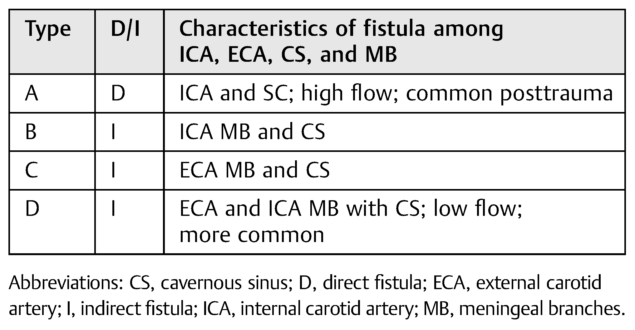 |
In general, CCF may be classified [3]:
- Pathogenically: spontaneous (rupture of an aneurysm) or traumatic
- Hemodynamically: high or low flow
- Angiographically: direct or dural fistula
In 1985, Barrow and colleagues proposed that CCF be classified according to the arterial supply for such communications [4] (Table 1).
Case Report
A 47-year-old black, female patient reports a car accident in which she was not wearing a seatbelt. She presented facial injuries involving the left labial commissure and the masseteric region on the same side, significant facial edema. and panfacial fracture (Figure 1).
A computed tomography (CT) was performed in a fourchannel spiral CT scanner (Toshiba Asteion 4; Toshiba, Tokyo, Japan) with axial, coronal, and sagittal views. Multiple frac-tures were identified on the face (Figure 2 and Figure 3) and on the left side of the SS region (Figure 4).
Thus, the possibility of CCF-type vascular complication was discussed with the neurosurgery team. Three-dimensional (3D) facial reconstruction was performed, using bone grafting and titanium (Ti) plates to obtain stable internal fixation of the facial skeleton (Figure 5). Treatment progressed well up to the 15th postoperative day (POD), when signs and symptoms of CCF began, and the patient had to be treated for it.
Discussion
CCF hardly ever takes place immediately after trauma [5,6]. In addition, it is associated with a series of signs and symptoms such as the classical CCF Dandy triad [4,5], which is characterized by pulsatile exophthalmos, hum, and vein dilation with chemosis.
CCF may result from direct orbital trauma and/or from fractures in the skull base.
In this case report, the authors present a case of panfacial fracture in a patient who, on the 15th POD, developed diplopia, ptosis, epiphora, pulsatile exophthalmos, and complaints of ringing in the orbital region. All signs and symptoms took place in the orbital region on the left side (Figure 6). Preoperative CT evaluation revealed the extension of the fractures at the base of the skull in the SS region. That made it possible to predict the occurrence of CCF.
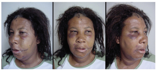
Figure 1.
Patient’s photos after hospital admission.
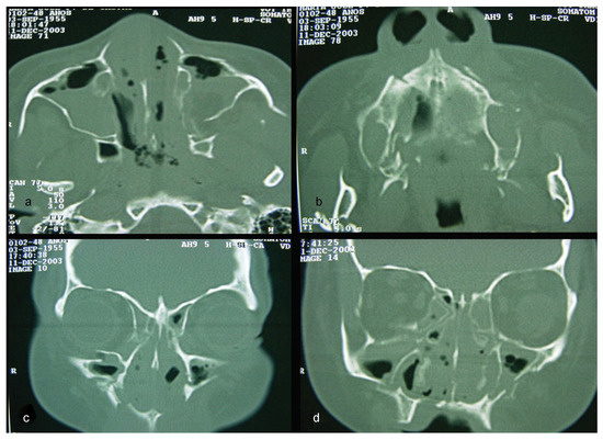
Figure 2.
(a–d) CT windows displaying multiple fractures in the middle third of the face or midface.
Differential diagnosis for CCF includes SOF syndrome (SOFS) with lesions on CN III, IV, V2, and VI; orbital apex syndrome, which includes the same lesions as SOFS in addition to lesions on the optic nerve (CN II); and cavernous sinus thrombosis (CST) [8].
Diagnostic confirmation is done using angiography [4,7]. Currently, cerebral digital subtraction angiography is used as the gold standard.
Examination of the patient showed normal results on the right side (Figure 7). The left side displayed significant alterations (Figure 8). It showed Type A CCF.
Endovascular treatment options to occlude Type A CCF include transarterial embolization, transvenous embolization, CA tying, fistula clipping, and exposure [8,9].
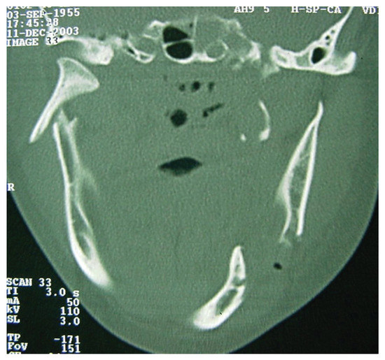
Figure 3.
CT windows displaying multiple fractures in the lower third of the face or mandibular region.
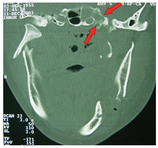
Figure 4.
CT windows with arrows highlighting fractures to the sphenoidal sinus.
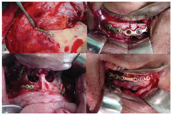
Figure 5.
(a–d) Stages of three-dimensional reconstruction of the face, using stable skeleton fixation by means of titanium plates and screws.
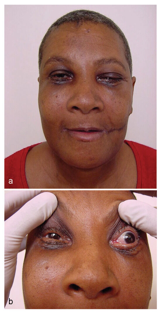
Figure 6.
(a, b) Patient’s appearance on the 15th postoperative day, start of carotid-cavernous fistula signs and symptoms.
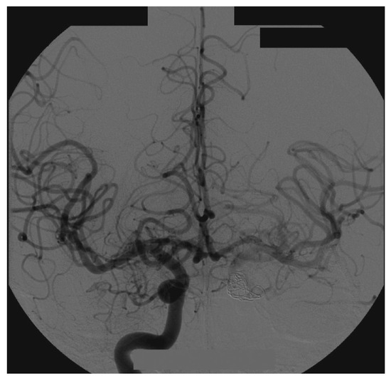
Figure 7.
Right side angiography, with coronal and normal views.
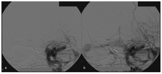
Figure 8.
(a, b) Left side angiography, with coronal view, showing congestion toward the left orbit.
In this case, the right femoral artery was punctured for the bilateral carotid and vertebral angiography. Type A CCF was treated by embolization of the left traumatic cavernous aneurism using a Tracker Excel 14 microcatheter (Boston Scientific Corporation, Neurovascular Division, Freemont, CA) and a TS 14 microguide (Micro Therapeutics, Irvine, CA) to selectively catheterize the CS on the left side, by depositing nine detachable GDC microcoils (Boston Scientific Corporation) associated with a detachable balloon (Figure 9) inside it.
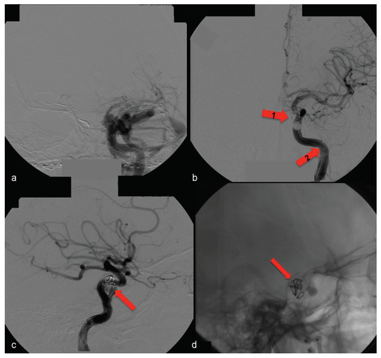
Figure 9.
(a) Left side angiography, with coronal view, showing congestion toward the left orbit. (b) The same coronal view with occluded fistula— arrow no. 1 highlights the activated balloon and arrow no. 2 highlights the microcatheter. (c, d) Left side angiography, with sagittal view showing the detachable microcoils used for permanent carotid-cavernous fistula occlusion (arrows).
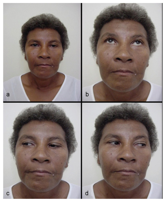
Figure 10.
(a–d) Patient 1 year postsurgery, with good appearance, normal ocular movements, and no other problems.
Thus, full occlusion of the arteriovenous fistula was achieved.
At the 1-year postsurgery control, no return of signals or symptoms was observed (Figure 10).
Currently, 11 years after the surgery, the patient does not present residual deformities (Figure 11), has good structural results (Figure 12), and has no complaints regarding CCF.
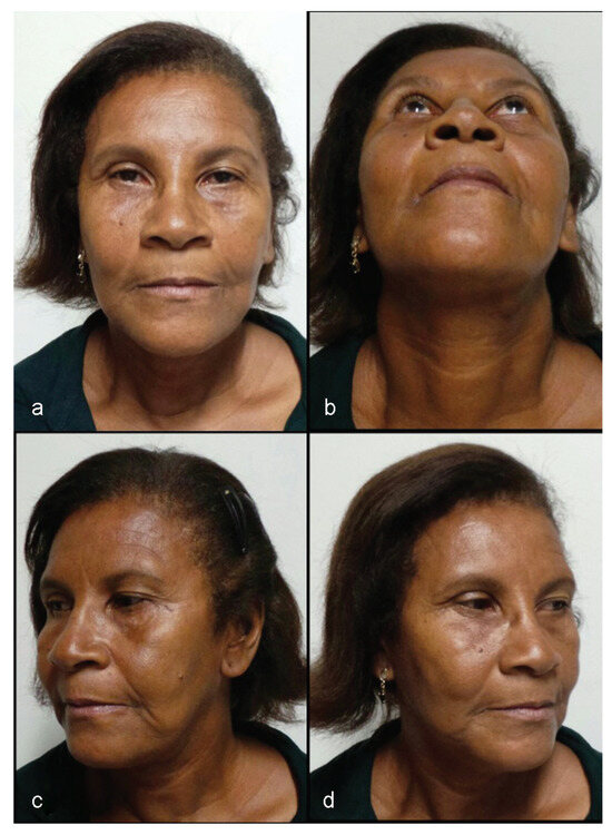
Figure 11.
(a–d) Patient 11 years postsurgery, with no residual deformity.
CT exams for control of microcoil positioning (Figure 13) have shown no alterations.
Conclusion
CCF, although rare, is a severe complication for patients victimized by craniofacial trauma. It may occur both in trauma to the midface and in mandibular fractures. Precise diagnosis is required for the correct treatment of this complication.
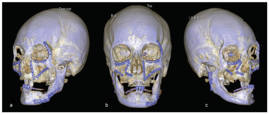
Figure 12.
(a–c) Eleven years postsurgery examination. Three-dimensional reconstruction showing good structural results.
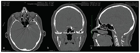
Figure 13.
Eleven years postsurgery examination. CT highlighting the position of detachable microcoils used to treat carotid-cavernous fistula on the left side. (a) CT in axial view; (b) CT in coronal view; (c) CT in sagittal view.
References
- Crowe, W.W.; Kelly, J.M. Ocular manifestations of carotid-cavernous sinus fistula following traumatic facial injury. Oral Surg Oral Med Oral Pathol 1956, 9, 917–927. [Google Scholar] [CrossRef] [PubMed]
- Wallick, K., IV; Davidson, P.; Shockley, L. Traumatic carotid cavernous sinus fistula following a gunshot wound to the face. J Emerg Med 1997, 15, 23–29. [Google Scholar] [CrossRef] [PubMed]
- Walls, R.D.; Helmy, E.S.; Timmis, D.P. Carotid-cavernous sinus fistula accompanying an isolated mandibular fracture. J Oral Maxillofac Surg 1989, 47, 1215–1221. [Google Scholar] [CrossRef] [PubMed]
- Vilela, M.A.P. Carotid-cavernous fistula. Rev Bras Oftalmol 2013, 72, 70–75. [Google Scholar] [CrossRef]
- Kim, J.W.; Kim, S.J.; Kim, M.R. Traumatic carotid-cavernous sinus fistula accompanying abducens nerve (VI) palsy in blowout fractures: Missed diagnosis of ‘white-eyed shunt’. Int J Oral Maxillofac Surg 2013, 42, 470–473. [Google Scholar] [CrossRef] [PubMed]
- Nocini, P.; Lo Muzio, L.; Cortelazzi, R.; Barbaglio, A. Cavernous sinuscarotid fistula: A complication of maxillofacial injury. Int J Oral Maxillofac Surg 1995, 24, 276–278. [Google Scholar] [CrossRef] [PubMed]
- Niamtu, J., III.; Campbell, R.L. Carotid cavernous fistula. J Oral Maxillofac Surg 1982, 40, 52–56. [Google Scholar] [CrossRef] [PubMed]
- Chang, C.M.; Cheng, C.S. Late intracranial haemorrhage and subsequent carotid-cavernous sinus fistula after fracture of the facial bones. Br J Oral Maxillofac Surg 2013, 51, e296–e298. [Google Scholar] [CrossRef] [PubMed]
- Gemmete, J.J.; Chaudhary, N.; Pandey, A.; Ansari, S. Treatment of carotid cavernous fistulas. Curr Treat Options Neurol 2010, 12, 43–53. [Google Scholar] [CrossRef] [PubMed]
© 2016 by the author. The Author(s) 2016.