1. Introduction
Continuous fiber reinforced thermoplastic matrix composite materials, with high fiber volume fractions, are of great interest in the area of structural composites due to potential benefits, including material cost, manufacturability and recyclability. However, processing fiber reinforced materials requires tooling to give form while the manufacturing process is in-progress. During the manufacture of composite materials, the matrix material must be in a state where it can flow freely to fully coat (wet out) the fiber reinforcement and form the desired structural shape. Tooling is used to control the shape of the composite material until the matrix becomes rigid. For thermoplastic matrix composites, with higher temperatures and pressures often required for consolidation than those required for thermoset matrix composites, tooling can become an even greater challenge.
Many applications of composite materials are dominated by the need for enhanced flexural performance rather than simply by in-plane properties. In metallic structures the generation of flexural performance is often addressed using T or I-beam section stiffeners on the surface of a metal sheet. However, with the relatively thin laminates typically used with composite materials, it is more common to utilize a lightweight continuous core which offers more support to the thin composite facesheets. As such, sandwich panels created with a composite laminate on each side of a lightweight core can require tooling of even greater complexity.
1.1. Sandwich Panels
Sandwich panels are often used to increase the flexural stiffness of a composite structure by increasing the area moment of inertia while not dramatically increasing the weight of the structure. Composite sandwich panels gain flexural stiffness and retain low mass by separating laminated composite facings with a lightweight core that resists the shear component of the load. The bending moments are transferred from the facesheets to the core via shear at the interface between the facesheet and the core implying that the core/facesheet bond, in addition to the shear properties of the core itself, is an important aspect of the structural performance of a sandwich structure.
A sandwich panel consists of 2 major subcomponents, the top and bottom composite facings, or facesheets, and the core, as indicated in
Figure 1. In practice, composite sandwich panels also incorporate some form of edge closures, or closeouts, as well as hardpoints. The properties of the composite facesheets do add to the bending stiffness but are not the primary component responsible for the through-thickness compression or shear stiffness of the sandwich panel. Increasing the core thickness increases the distance between the facings increasing the moment of inertia and the resulting bending stiffness. Compression and shear stiffnesses of a composite sandwich panel are primarily controlled by the core. Edge closures are used to protect the core and, in certain cases, add to the stiffness of the sandwich panel increasing the bending, compressive and shear stiffness [
1]. In addition, edge closures and hard points are used to transfer loads into, and out of, the sandwich structure.
1.2. Truss Core Sandwich Panels
Truss, or lattice core structures have an advantage of a reduced material weight with a strength and stiffness comparable to many foam and honeycomb cores. Therefore, using a lattice structure as a core offers the potential of a reduced weight sandwich panel, while still maintaining a high compression strength and flexural stiffness [
2,
3]. A lattice core used in a sandwich panel replaces the typical honeycomb or foam core and can take advantage of various truss geometries and material configurations. While the lattice structure can be produced from a thin isotropic material [
4], or even via additive manufacture of unreinforced or short fiber reinforced polymers [
5], placing continuous fiber reinforcement within the lattice of the core promises an increase in performance with a decrease in weight of the resulting truss core sandwich panels. Lattice cores, also often described as corrugated cores, can be created with the corrugations in a single direction, such as those that may be pultruded from fiber reinforced composites for civil infrastructure applications [
6]. However, bi-directional corrugated lattice cores, with continuous fiber reinforcement, result in significantly greater manufacturing complexity. Such lattice cores have predefined shapes, including, tetrahedral [
7], kagome [
8], pyramidal [
9,
10], and Navtruss [
11].
The pyramidal core geometry has been manufactured with a 3D printing approach and a continuous fiber reinforcement [
12], waterjet cut and then manually assembled [
13], and compression molded with a complex set of tooling [
14]. Two methods have been used to bond the core to the facings, a mechanical interlocking method called buried node joining [
10,
13] and adhesive bonding [
9,
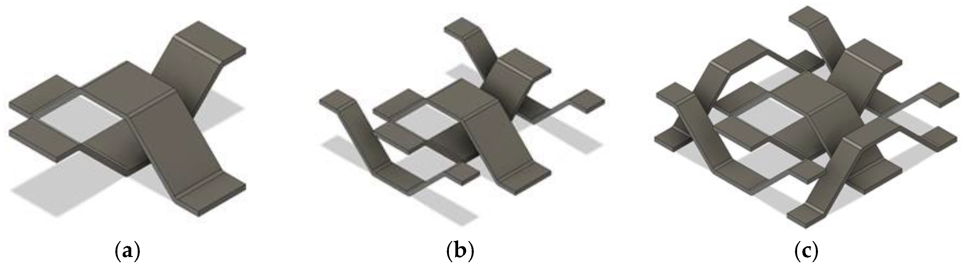
15]. Truss core sandwich panels manufactured with the buried node techniques performed better than panels made with just adhesive bonded joints due to a stronger joint at the truss core/facesheet interface but are more difficult to manufacture. The surface area to bond the core to the facings for pyramidal truss cores is relatively small, which can compromise the shear transfer between the facesheets and the core. Thus, in terms of load transfer between the facesheets and the core, the Navtruss geometry has a distinct advantage. Bi-directional Navtruss core structures are scalable, as shown in
Figure 2, and have been manufactured from carbon fiber reinforced epoxy prepregs using complex corrugated tooling, then cut, woven and bonded to the facings [
2]. The Navtruss cores produced for the current testing utilize a 2 strut core unit cell.
An additional advantage of this form of manufacture is that the facesheets and truss core can be made from the same material which simplifies the prospects of recycling as there is no need to separate the core from the facesheets as is necessary for conventional sandwich panels. To further facilitate recyclability, being able to produce such a truss core structure from a thermoplastic matrix composite would be a major step forward. Thus, while truss core sandwich panels can demonstrate significant increases in strength and stiffness vs. weight, construction cost, especially for bi-directional lattice cores, becomes a major consideration in the decision between honeycomb, foam, or truss cores, with honeycomb and foam cores currently being significantly less expensive to manufacture. Reducing the manufacturing complexity of truss core sandwich panels, especially from thermoplastic matrix composites, could greatly impact all aspects of the composites industry by reducing the weight and cost of sandwich panel structures, while improving the recyclability.
1.3. Direct Digital Manufacture of Continuous Fiber Reinforced Thermoplastic Composites
Current efforts are being made to use direct digital manufacturing techniques to manufacture continuous fiber reinforced thermoplastic composites [
16,
17,
18,
19]. Continuous fiber reinforced thermoplastic composites (CFRTC) offer enhanced recyclability to the user of composite material structures, but the manufacturing costs of CFRTC are still substantial. Numerous CFRTC manufacturing methods have been investigated, yet for the most part these manufacturing techniques require the use of complex tooling for the realization of continuous fiber reinforced composite structures. However, over the past decade several approaches that combine concepts of extrusion-based 3D printing, such as fused filament fabrication (FFF), and continuous fiber placement have been described. The current state of commercial continuous fiber reinforced composite manufacturing with FFF are the MARK TWO and MARK X from Markforged. These machines make use of a proprietary FFF filament that is co-extruded with a small fraction (14% by volume) of continuous fiber to add in-plane reinforcement to thermoplastic parts [
20]. The addition of continuous fiber reinforcement can substantially improve the strength and stiffness of the 3D printed thermoplastic part [
17,
18,
21].
While the use of extruded thermoplastic filament with small amounts of continuous fiber can be beneficial in reinforcing a plastic 3D printed component, the low fiber volume fractions do not result in the performance expected from traditional fiber reinforced composite laminates. For the automation of manufacture of high fiber fraction laminates, the use of robotic fiber placement systems [
22] has been demonstrated. With a multi-axis manufacturing machine, it is possible to place continuous fiber reinforced preimpregnated (prepreg) materials on multiple faces of a defined tool geometry. Further, such systems can place fiber along specified load paths, on the tool-defined surface, creating a tailored composite structure that can better take advantage of the potential of a continuous fiber reinforced composite. However, this approach limits the path control in-plane since the prepreg tape cannot readily shear to enable steering [
23].
To address these shortcomings, an approach using a commingled continuous fiber feedstock has been described [
24,
25,
26]. Commingled roving, or hybrid yarn, is a commercially available raw material that consists of fibers of a reinforcement and of a thermoplastic matrix material within the same tow. Commingled rovings are available with a variety of different reinforcement fibers including, carbon and glass fibers, and different thermoplastic matrix fibers such as Polyether ether ketone (PEEK), Nylon, and Polyethylene terephthalate (PET). The reinforcing fiber volume fraction of the commingled material is predetermined by the manufacturer but is generally in the range of 30% to 55%. Commingled feedstocks offer benefits in terms of volume fraction control, wetout and consistency over methods where the reinforcing fiber would flow through a separate heated low viscosity thermoplastic matrix material in some form of mixer head [
27,
28]. Rather than maintaining a molten source of the thermoplastic matrix material in a mixer head, the commingled feedstock is locally heated to enable matrix flow just prior to placement and consolidation. During processing of the commingled material tow shearing is possible because sliding of the reinforcing fiber is not restricted as it would be with a premanufactured fiber filled filament, or a prepreg tape [
26]. When using a commingled roving the thermoplastic matrix does not have to flow long distances to wet out the fibers, enabling more rapid rates of extrusion and improving fiber wet out. Improved positional fidelity in thermoplastic commingled tow steering on a tool surface has been accomplished through the application of controlled cooling to rigidize the thermoplastic material in desired portions of a preprogrammed path [
26,
29]. In conjunction with controlled cooling, efforts related to enhanced consolidation on the tool surface have resulted in thermoplastic matrix composites with fiber volume fractions greater than 50% and void fractions less than 3% without post processing [
30].
As an alternative to using these automated approaches to creating continuous fiber reinforced thermoplastics that are positioned and consolidated on essentially conventional tooling, there have been a limited number of demonstrations of placing, and rigidizing, composite strands in free space as an approach to reduce tooling requirements [
31,
32]. Those efforts utilized commingled feedstock, consolidated in a nozzle and cooled on exit, to generate rigidized composite rods used to demonstrate bonded pyramidal trusses.
More recently, an approach combining automated placement and local programmed cooling of commingled feedstock has demonstrated the potential to digitally manufacture a complete pyramidal truss core panel using off-the-tool surface consolidation [
33]. The principal challenge of this approach is related to tow consolidation and void removal, which must be accomplished as the tow exits the extrusion nozzle, without the aid of pressure generated between the nozzle and a tool surface. The current effort focuses on using prior developments as the basis for manufacturing Navtruss core sandwich panels to demonstrate placement and rigidization of the commingled tow on, and off the tool surface. This radically reduced tooling approach, as well as compression and shear performance of the resulting truss core panels are compared to specimens manufactured using more conventional compression molding of thermoplastic prepreg tapes. Thus, the goal of this work is to demonstrate how a new approach to the manufacture of continuous fiber reinforced thermoplastic composites, that can be applied to the construction of truss core sandwich panels, can remove the tooling constraint that has previously limited the manufacturing competitiveness of truss core structures.
2. Experimentation
Experiments were developed to demonstrate the ability of direct digital manufacture to produce high volume fraction continuous fiber composite structures using a combination of tow placement on and off-the-tool surface. In addition to demonstrating the potential to radically reduce the amount of tooling required to manufacture a Navtruss core sandwich panel, specimens were produced to evaluate the compression and shear modulus. Corresponding Navtruss core panels were fabricated from compression molded prepreg sheets as a basis for performance comparison.
2.1. Materials
The composite constituent materials used in the manufacture of the evaluation Navtruss panels were continuous E-glass fiber reinforcement and a Polyethylene terephthalate (PET) matrix material. Two different forms of these materials were used as the feedstock for the two different composite truss core panel manufacturing techniques employed, (i) commingled tow and (ii) prepreg tape. The commingled tow was Compofil -PET-70-R-2690N from Jushi [
34] which has an E-glass fiber content, by volume, of approximately 55%. The prepreg used was Polystrand 5843, unidirectional E-glass reinforced Polyethylene terephthalate (PET) with nominally 43% reinforcement by volume [
35]. When processed, differential scanning calorimetry (DSC) indicated that the PET matrix materials were similar, showing a glass transition temperature (T
g) of approximately 78 °C.
2.2. Digital Manufacture of Navtruss Test Panels: Equipment
A custom fabricated dual gantry automation platform, shown in
Figure 3, was developed to create Continuous Fiber Reinforced Thermoplastic Composite (CFRTC) structures using a commingled tow feedstock. The continuous fiber composite placement head is mounted to the primary gantry, while an extruder, mounted to the second gantry, can be used to 3D print neat thermoplastics using commercially available 3D printing filaments. The ability to use both the continuous fiber commingled roving and filament-based printing, in parallel, create a unique environment where tooling or support structures may be placed with neat thermoplastic and where continuous fiber reinforced composites can be manufactured with, and without, tooling.
While the end effector used with the neat thermoplastic filament is a lightly modified commercial 3D printer hot-end, the commingled tow extruder is custom developed and somewhat more complicated. This spring-loaded end effector, for consolidating commingled tow feedstock on a tooling surface, has been described previously in the literature [
30,
36]. The use of this spring-loaded end effector allows improved control of the consolidation force through a programmed compression of a spring of known spring constant. During preliminary trials of off-the-tool placement and rigidization it was discovered that further hardware development was necessary to increase the composite quality [
33]. Reducing the nozzle diameter and increasing the length, as shown in
Figure 4, allowed access to tighter spaces, such as corners or between previously placed fiber as has been discussed in relation to a 5-axis automation system and the positioning and consolidation of the commingled tow on more complex tool surfaces [
37].
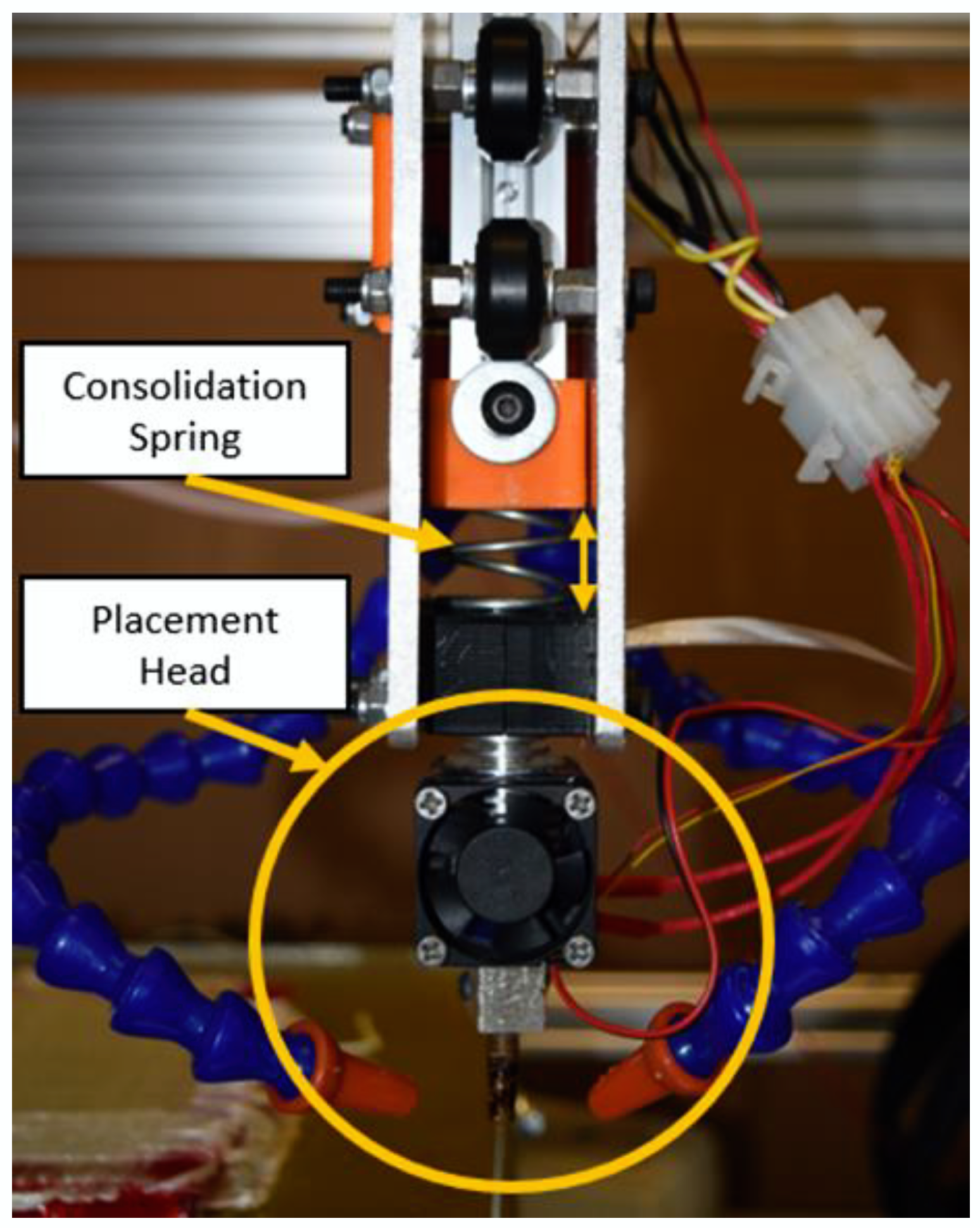
A computer-controlled cooling system was also developed to enable tight radius turns on a tool surface through local forced air cooling. In addition to allowing the automated manufacture of a fiber reinforced facesheet on the tooled surface, this ability to actuate the cooling air flow and locally improve the adhesion to the prior material is invaluable in the initiation of off-the-tool fiber paths. The spring-loaded extruder, extended nozzle and air-cooling flow direction devices are seen in
Figure 5.
2.3. Digital Manufacture of Navtruss Test Panels: Overview
The direct digital manufacture of an individual Navtruss core panel starts with a fiber reinforced facesheet placed and consolidated on the flat, heated, tool surface using the custom commingled tow placement end effector. This is followed by the deposition of a neat thermoplastic frame around the perimeter of the facesheet using the second gantry and the conventional 3D printer extruder. This thermoplastic frame serves the dual purpose of a truss core manufacturing aid and as an edge closeout, in concept, both protecting the truss core elements and enabling loads to be transferred in, and out, of the structural panel. Commingled tow is then tacked in specified positions on the top of the edge closeout and pulled across to a corresponding location on the opposite side. These tensioned tows become a form of built-in scaffolding that improves the ability to make changes in direction of the off-the-tool rigidized commingled tows that create the truss segments of the core. The placement of the core can be broken down into 4 steps, continuous fiber reinforced scaffolding in the ‘1’ direction, truss core in the ‘2’ direction, scaffolding in the ‘2’ direction then truss core in the ‘1’ direction. Once the Navtruss core portion is complete, the top facesheet is applied.
2.3.1. Bottom Facesheet Manufacturing
The bottom facesheet is a crossply laminate manufactured from commingled tow on the tool surface. The process has been previously described [
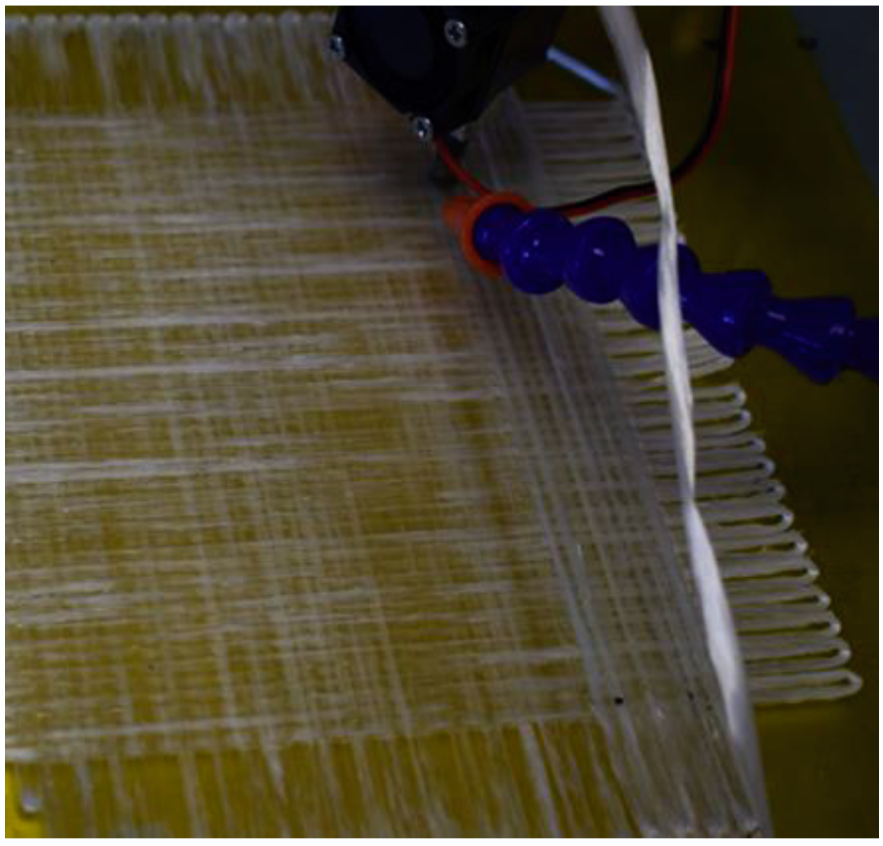
37]. The general approach is repeated here for completeness. With the commingled tow properly adhered to the substrate the composite placement head moves at 180 mm/min across the tool surface placing and consolidating the CFRTC strand as it moves. Once the placement head travels a distance equivalent to just more than the size of the required laminate (~160 mm in this case) the cooling airflow is triggered by the program enabling a 180° turn to be executed to begin the adjacent fiber path in the opposite direction. Once the placement head is moving back across the tool surface the cooling air is turned off to improve consolidation. The placement head then moves back and forth repeating the process until the first layer of the bottom facesheet is complete. When the first layer is complete the composite placement head starts placing the next lamina in a similar fashion but with a different fiber orientation, as shown in
Figure 6. During the placement of the second and the third lamina of the composite facesheet, the composite strands are being placed directly onto the previous continuous fiber reinforced/PET layer. The thermoplastic adheres to the previous layer quickly and, when cooled, the bond is strong enough to withstand the tensioning force within the nozzle and can be doubled back on itself, at the end of each pass. The bottom face sheet has a 3-ply stacking sequence of [0/90/0]
T.
2.3.2. Edge Close-Out Manufacture
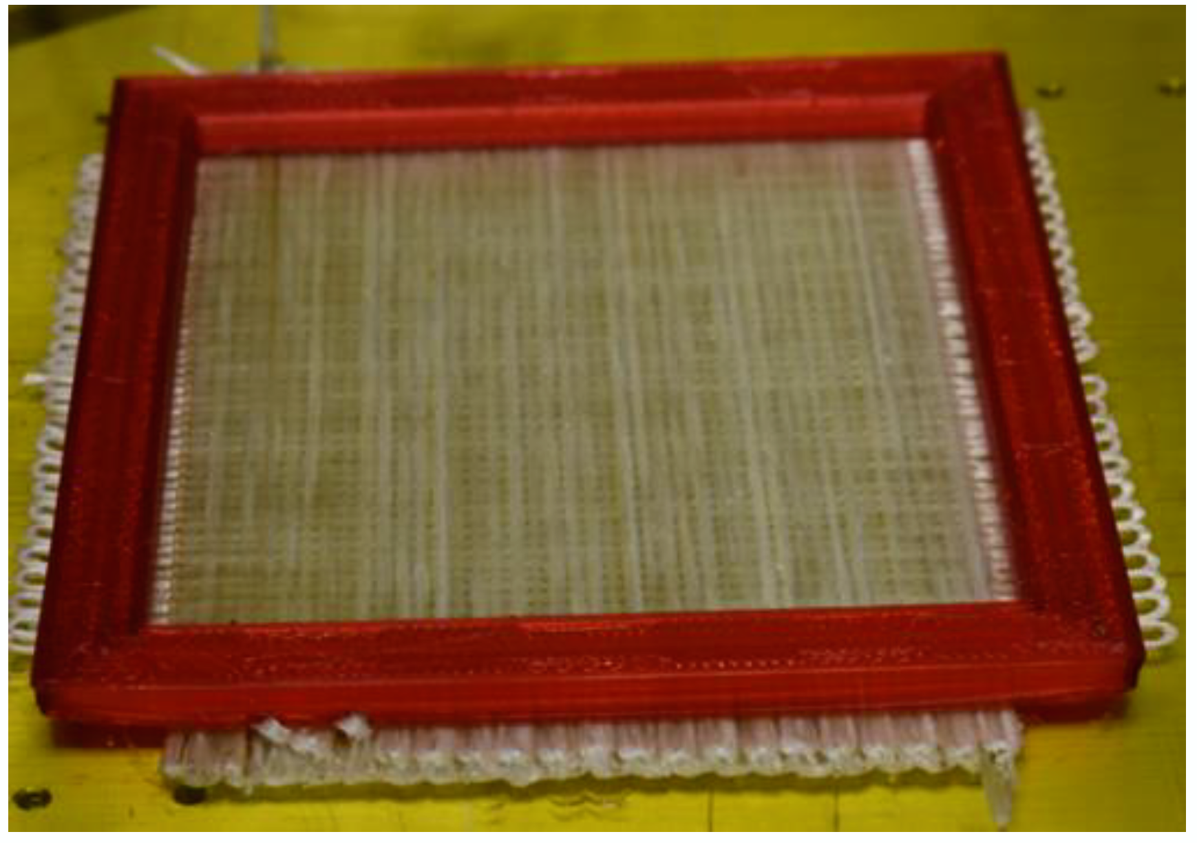
When the bottom face sheet is completed the fiber placement nozzle moves to a safe location and the neat thermoplastic placement head begins to print the edge closeout. The edge closeout is manufactured using a traditional FFF additive manufacturing approach, being built up layer by layer, resulting in the red edge closeout shown in
Figure 7.
After the neat thermoplastic PETG edge closure is manufactured, the bed is cooled to room temperature and the gantry for printing the neat thermoplastic is moved to a safe location for the remainder of the processing of the truss core sandwich panel. The composite placement gantry is activated and starts the digital manufacture of the Navtruss core.
2.3.3. Continuous Fiber Reinforced Thermoplastic Navtruss Core Manufacturing
One significant challenge in off-the-tool commingled tow positioning and rigidization is the issue of direction changes in free space. Even though the tow is rigidized as it exits the nozzle, the tension required to pull tow through the nozzle is great enough to flex the rigidized tow, losing positional fidelity. To counter this, commingled tow is tacked to one side of the edge closure and rigidized as it is pulled through the air to the opposite side of the edge closure where it is tacked in place. This rigidized, tensioned tow becomes integral scaffolding which allows direction changes of the truss core to be more accurately accomplished. The pattern of this scaffolding is dependent upon the type of truss core being created [
33]. For the Navtruss core used in this effort, the first set of scaffold tows are positioned in parallel pairs, 10 mm apart and separated from the next pair by 30 mm, as shown in
Figure 8.
The continuous fiber reinforced scaffolds in the ‘1’ direction must span the 120 mm between the two sides of the 10 mm high edge closure. To generate sufficient stiffness over this free span, four (4) fully processed strands of commingled tow are positioned on top of one another to create each scaffold. This minimizes the scaffold deflection that might be introduced as the tensioned commingled tow moves in the programmed motion necessary to create the truss segments.
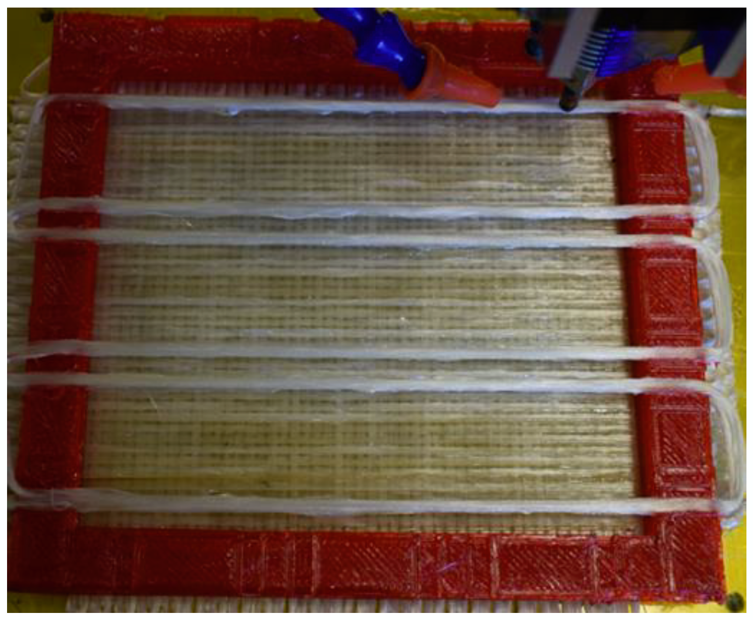
The generation of the truss core geometry requires point to point manufacture, from the lifting point at which the tow leaves the facesheet/tool surface to the top corners of the first scaffold tow, horizontally across to the second scaffold tow and then back to the pause point on the facesheet/tool surface, as shown schematically, in the G-Code path, in
Figure 9.
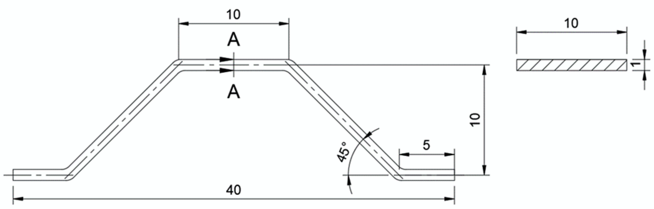
With the dimensions described, the truss segments have nominally 10 mm of horizontal length in contact with the lower facesheet and 10 mm across each scaffold pair which will ultimately be fused to the upper facesheet. The remainder of the 30 mm gap between scaffold pairs, combined with the 10 mm close-out height results in a nominal 45° truss angle transitioning from bottom to top facesheet. An individual truss core segment is shown in
Figure 10.
The two critical areas for manufacturing a single tow in the truss geometry are when the CFRTC strand is being placed onto the facesheet, the pause point, and when the CFRTC strand is being pulled off the bottom facesheet, the lifting point. At each of these points, local cooling is activated to rigidize the tow and fuse it to the lower facesheet, resulting in an ability to change direction without pulling some of the already positioned tow out of place. The composite placement head moves down from over the scaffolding, fusing the truss tow segment to the scaffold at the transition, until it reaches the pause point. At the pause point cooling is turned on and the placement head pauses for two seconds allowing the CFRTC strand to cool and adhere to the facesheet. With the strand fused to the facesheet at the pause point, the cooling is turned off to improve the consolidation against the facesheet as the tow moves to the lifting point. Then, before leaving the plane of the facesheet, local air cooling is once again applied to ensure a strong bond is achieved so that the tow consolidated against the facesheet is not peeled off. Because cooling was applied, the length of malleable composite in the newly placed tow is roughly only the radius of the nozzle, or 2 mm. This known nozzle radius is accommodated for in the G-code. In addition, as the placement head leaves the plane of the facesheet, where the commingled tow exits the nozzle at 90° and moves upward, the relative angle between the nozzle exit and the movement direction changes from 90° to 45°, as shown schematically in
Figure 11, and the cross-sectional geometry of the rigidized CFRTC strand changes to be more rod-like rather than flat and spread out. When the placement head moves over the composite scaffolding a bond is formed between the scaffolding and the CFRTC strand. After reaching an adequate height to go over the scaffolding the nozzle, again with the tow at an exit angle of 90°, moves across the scaffolding which tends to flatten and spread the tow. Finally, as the nozzle moves downward the relative tow exit angle changes from 90° to 135°, further spreading the tow, which decreases the center thickness and increases the width of the CFRTC strand.
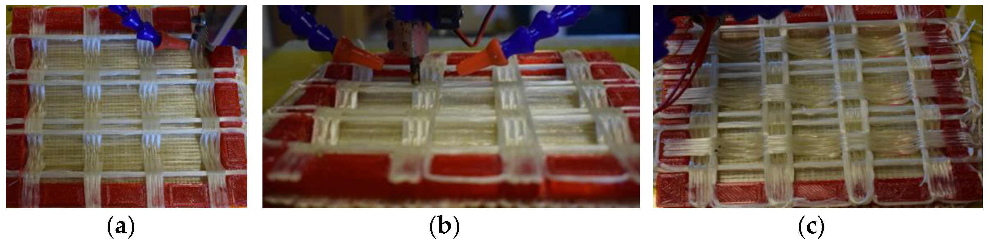
Thus, using a 3-axis system for the placement of the tow in the truss geometry results in a changing degree of consolidation and a cross-sectional geometry dependent on the position within the length of the truss segment. The resulting 3 tow wide truss core in the ‘2’ direction can be seen in
Figure 12a.
Once the ‘2’ direction truss segments are complete, scaffold tows are placed across the edge closure frame, in the ‘2’ direction as shown in
Figure 12b, immediately adjacent to the sides of the truss core segments. In this case, the free span is only 30 mm as the scaffold tows go from edge closure to the top of each truss segment. Thus, only 2 tows, stacked on top of each other, are necessary to generate sufficient scaffold stiffness in the ‘2’ direction.
Once this second set of scaffolding is complete, the Navtruss core can be completed by placing the truss segments in the ‘1’ direction following the same procedure described previously. The completed truss core, integrated with the lower facesheet and the edge close-out, is shown in
Figure 12c. The steps described in
Figure 11 and
Figure 12a–c show the constrained space within which the vertical moves must be accommodated. These close confines also demonstrate the need for the specially developed long reach nozzle, shown earlier in
Figure 4, to ensure consolidation of the portions of the truss segment against the lower facesheet without generating interference with the scaffolding or the truss core segments running in the opposite direction.
2.3.4. Top Facesheet Manufacture
Placing the top facesheet utilizes the same G-code as the bottom facesheet, but the Z height is adjusted to position the facesheet directly on top of the upper truss segments, fusing, and creating the core-to-facesheet bond as facesheet tows are positioned. The second layer at [90°], shown in
Figure 13, is placed at the same Z-position as the first upper facesheet layer [0°] and utilizes the consolidation spring of the end effector to allow the head to move up and down and follow the undulations of the first layer, yet apply a controlled consolidation force.
The spring-loaded end effector improves the ability to consolidate the lamina and decreases fluctuations in placement force while placing composite strands as part of the top facesheet. The effective stiffness of the first layer of the facesheet is a function of the distance between supports. The distance between the supports of the test panels is 30 mm in most locations and 140 mm in the others. The second layer is consolidated against the first and the third layer is consolidated onto the stiffer combination of the first and second plies. A completed, digitally manufactured specimen, with the outer edge closure removed in preparation for mechanical testing, is shown in
Figure 14.
Due to differences in the processing and consolidation of each of the three segments of the digitally manufactured Navtruss test panels, the consolidation quality, and therefore the fiber fraction and void fraction vary. The lower facesheet, consolidated against the heated tooling surface, had the most consistent properties. Segments, representative of the lower facesheet were measured to have a nominal fiber volume fraction of 52%, and a void content less than 5%, based on the composite constituent content evaluations consistent with ASTM D792, Standard Test Methods for Density and Specific Gravity (Relative Density) of Plastics by Displacement [
38] and ASTM D3171, Standard Test Methods for Constituent Content of Composite Materials [
39]. Truss core segments were not measured for fiber and void fractions as the tow geometry varied throughout and the individual tow position relative to an adjacent tow was somewhat inconsistent. However, it is important to note that the total number of E-glass reinforcing fibers is fixed, based on the TEX of the commingled feedstock. Finally, the upper facesheet was more poorly consolidated than the lower facesheet. No direct measurements of the fiber and void fractions of the upper facesheet were performed as the consolidation, and associated thickness, varied with position. So, while the fiber count in the upper and lower facesheets were identical, as was the total amount of thermoplastic matrix, the fiber fraction of the top facesheet is lower than that of the bottom facesheet and the void fraction is higher. For the compression and shear modulus testing, the properties of the facesheets play a small role, as the properties of the sandwich panel are dominated by the performance of the truss core segments and the strength of the bond to the facesheets. In future applications of truss core panels manufactured with radically reduce tooling, the quality of the top facesheet is expected to approach that of the lower facesheet as the facesheet thickness increases.
2.4. Compression Molded Baseline Navtruss Panel Manufacture
To create a baseline for comparison with the CFRTC Navtruss panel it was decided that panels would be produced by compression molding, a technique common in the literature [
2]. A set of aluminum dies, shown in
Figure 15, were manufactured with a geometry equivalent to that of truss segments of the CFRTC Navtruss design. The Navtruss core truss segments were then manufactured by compression molding seven (7) plies of a unidirectional thermoplastic glass fiber reinforced PET prepreg into a unidirectional laminate between the matched aluminum dies. This number of plies was chosen to match the amount of glass fiber reinforcement in the truss segments of the digitally manufactured panels, which was a known value, based on the TEX of the commingled feedstock. The compression molding was performed using a small laboratory hot press, with a platen size of 200 mm × 200 mm, that incorporates both heating and cooling control.
Chemlease 41-90EZ was applied to the aluminum matched dies to ensure proper release of the glass fiber/PET prepreg. The UD prepreg was cut into 76 mm × 152 mm strips with the fiber parallel to the long direction of the strip. The seven prepreg strips, layered on top of each other, were positioned in the middle of the die set and the platens where heated to 290 °C. Once at temperature, the dies were closed until the alignment pins engaged the alignment holes and 620 N of press force was applied to consolidate the fiber reinforced thermoplastic composite laminate. With the plies fused together, the mold and platens were slowly cooled under pressure. When the temperature dropped below 70 °C the pressure was removed, and further cooling was allowed to take place in air until a safe handling temperature was reached. The 76 mm × 152 mm laminates were then trimmed to length and cut to a nominal width of 10 mm using a high-speed water cooled saw to create the compression molded truss core segments. The edges of the segments were wet sanded to remove any defects introduced by the cutting process and then dried for one hour at 55 °C. The top and bottom facesheets were cut from a prefabricated E-glass/PET [0/90/0/90/0]T laminate with a nominal thickness of 1.4 mm. The facesheets were cut to 152 mm × 152 mm in preparation for the assembly of the Navtruss panel.
Representative sections of both the compression molded truss segments and the prefabricated facesheet material were measured to have a nominal fiber volume fraction of 45%, and a void content of 3% or lower, based on the composite constituent content evaluations consistent with ASTM D792, Standard Test Methods for Density and Specific Gravity (Relative Density) of Plastics by Displacement [
38] and ASTM D3171, Standard Test Methods for Constituent Content of Composite Materials [
39].
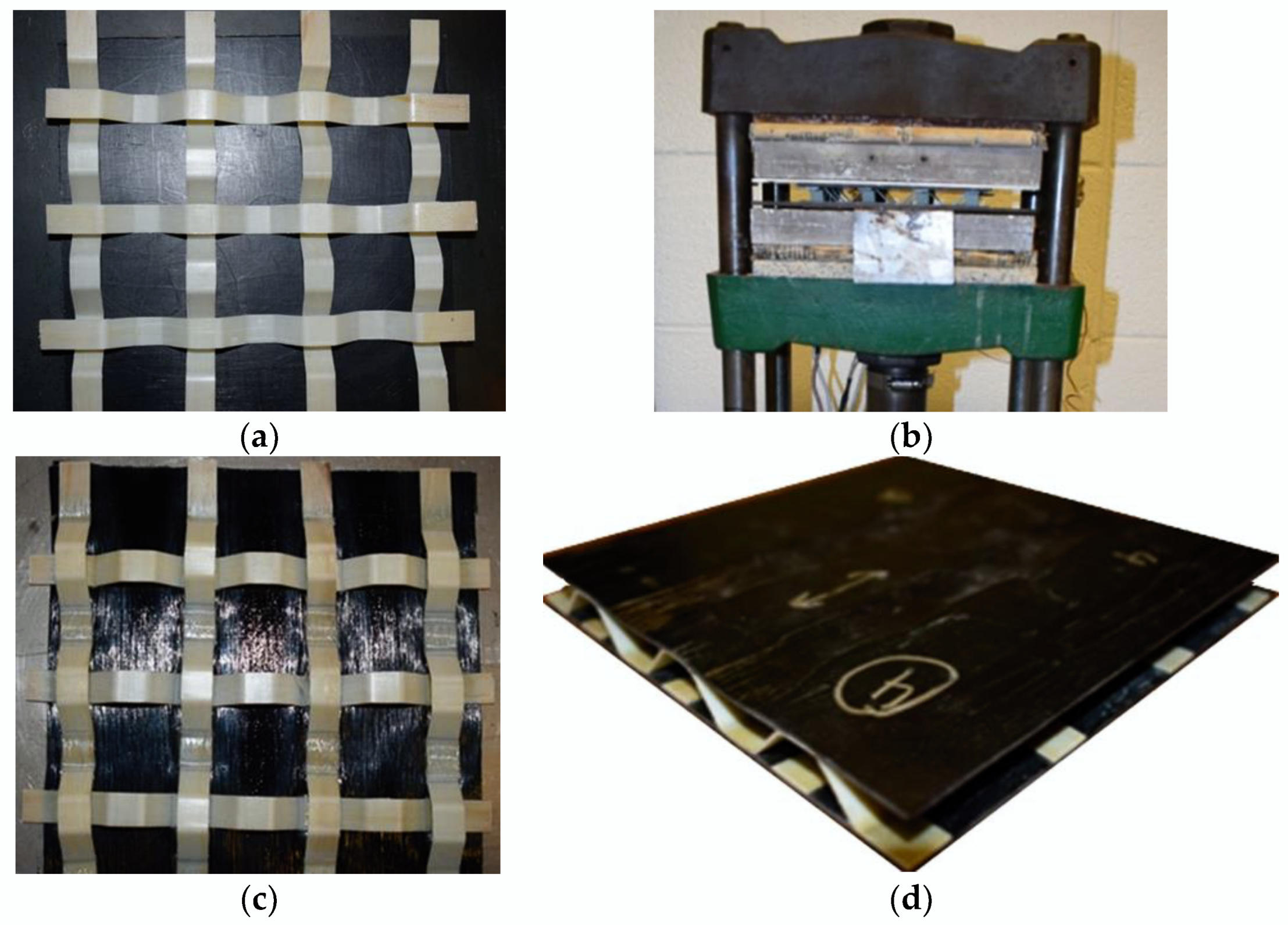
Using heat and a small amount of pressure, the truss core segments were fusion bonded by arranging the truss core segments, first on one facesheet, as in
Figure 16a. This was then placed, facesheet down, on the lower press platen. The lower platen, only, was heated to facilitate the fusion bond between the facesheet and the contacting regions of the truss core segments. The cold upper press platen was then engaged to apply a slight pressure, as shown in
Figure 16b. The applied pressure was just sufficient to push the core into the hot facesheet without crushing the core. Once the facesheet and core bond areas reached a sufficient bonding temperature the single-sided panel was cooled and removed from the press,
Figure 16c. This cooled half of the panel was then inverted and placed on the other facesheet. The heating process was repeated, with this second facesheet against the hot lower press platen and the previously joined facesheet in contact with the cool upper press platen. Maintaining this temperature gradient keeps the truss core stiff enough to support a consolidation force yet allows the core sections and facesheet in contact with the heated lower platen to fuse. Once the facesheets were joined to the truss core segments the sandwich panel was trimmed to its final size with a high-speed water-cooled saw and dried at 55 °C for one hour. The resulting baseline compression molded Navtruss core panel is shown in
Figure 16d.
3. Navtruss Core Sandwich Panel Performance Evalution
To evaluate the effects of manufacturing parameters and to determine some preliminary mechanical properties of the digitally manufactured Navtruss core panels, 4 digitally manufactured and 3 baseline compression molded specimens were produced. The 7 specimens were tested for modulus in both compression and shear.
3.1. Test Specimens
The details of the 7 test specimens are summarized in
Table 1. The compression molded specimens, CM1–CM3 were manufactured using identical parameters while, each of the digitally manufactured specimens, DM1–DM4, had a slight change incorporated into the processing. The process variations in DM1–DM4 were: DM2–DM4 followed the procedure outlined in the previous section on digital Navtruss manufacturing, incorporating localized cooling only at the transition points, in an effort to improve consolidation in all other locations. For DM1, cooling was active throughout the complete manufacture, including during the manufacture of the facesheets. Specimens DM3 and DM4 used 4-layer facesheets versus the 3-layer facesheets of DM1 and DM2. DM1–DM3 used a placement nozzle temperature of 290 °C, while DM4 was manufactured with a placement nozzle temperature of 310 °C, to better understand the effects of enhanced matrix flow.
The designed Navtruss core thickness was 11 mm for all specimens. For both groups of specimens there was a decrease in core thickness when manufactured. Compression molded specimens had the largest thickness variation from the designed thickness, with an average core thickness of only 8.31 mm, while the digitally manufactured specimens had an average core thickness of 9.78 mm. In the compression molded core, these differences in the thickness occurred from the process of joining the truss core segments to the facesheet. In the digitally manufactured specimens, the reduction in the core thickness was from a combination of the variation in tow consolidation on the lower facesheet and across the scaffolding, as well as from the operation of consolidation the top facesheet on the truss core.
The facesheets of the compression molded specimens were pre-consolidated plates, resulting in top and bottom facesheets that were nominally 1.4 mm thick. However, the digitally manufactured specimens had notable thickness variations between the top and bottom facesheet, with the thinner bottom facesheet consolidated against the tool surface and the top facesheet only consolidated against the core itself. The thickness for the digitally manufactured 2-layer bottom facesheet of specimens DM1 and DM2 was nominally 1.3 mm with a nominal top 2 laminae thickness of 1.7 mm. Correspondingly, the thickness for the digitally manufactured 3-layer bottom facesheet of specimens DM3 and DM4 was nominally 1.6 mm with a nominal top 3 laminae thickness of 1.9 mm.
3.2. Structural Evaluation
To investigate the effects of the process variations and the structural potential that the direct digital manufacturing approach for a Navtruss core sandwich panel offers, core compression and shear modulus were measured for each of the specimens. Testing followed ASTM C365, Standard Test Method for Flatwise Compressive Properties of Sandwich Cores [
40] and ASTM C273, Standard Test Method for Shear Properties of Sandwich Core Materials [
41] and was performed to evaluate and compare the moduli of the direct digitally manufactured and of the baseline Navtruss core sandwich panels. To accommodate the test protocols, the regions that included the neat thermoplastic edge closures of the digitally manufactured panels were trimmed away, leaving the exposed truss core.
3.2.1. Compression Modulus
The core compression modulus of each Navtruss sandwich panel was measured, based on ASTM C365 [
40]. Core compression modulus translates to the stiffness of the core which requires recording the load applied through the thickness and the corresponding displacement.
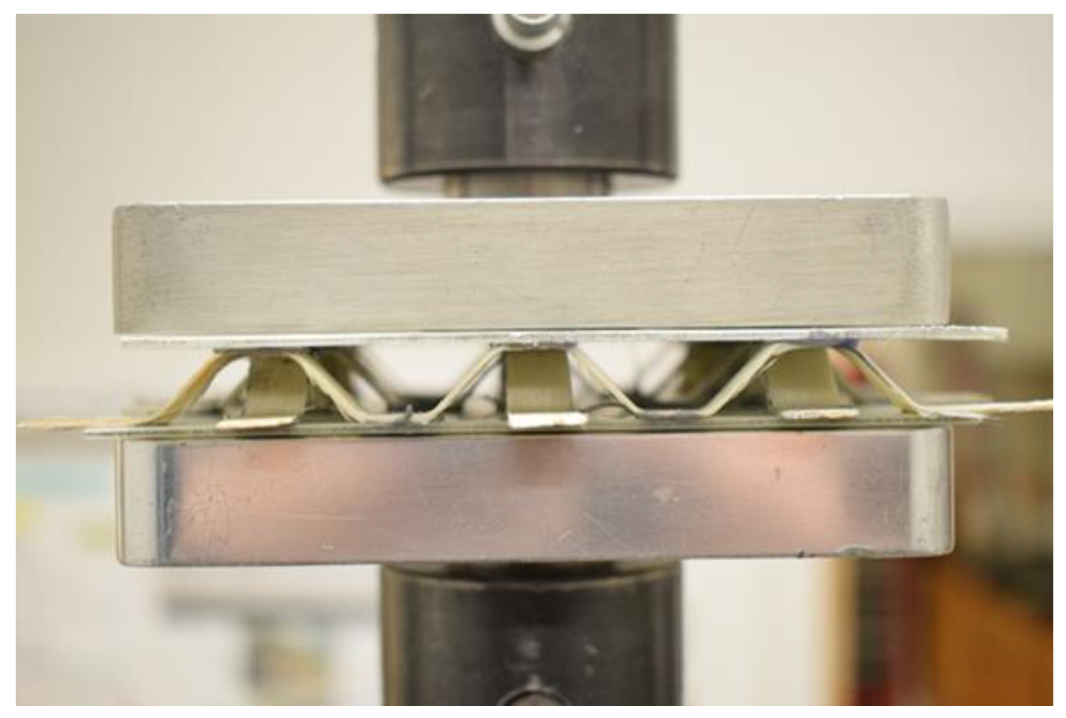
Figure 17 shows the testing configuration with a compression molded specimen placed between the compression plates of the testing apparatus.
For the Navtruss geometry a single cell size of the core is large compared to traditional honeycomb core structures. Since ASTM C365 specifies specimen size based on a minimum of 9 “cells”, a test panel of approximately 140 mm × 140 mm was required. A load of 4.45 kN was applied at a loading rate of 0.51 mm/min followed by specimen unloading. Each specimen was loaded 5 times as a measure of repeatability. The method of ASTM C365 was followed to determine the compression modulus from the measured loads and displacements.
3.2.2. Shear Modulus
The core shear modulus of the Navtruss sandwich panels was measured, based on ASTM C273 [
41]. In this procedure, core shear modulus is found using the linear region of the load vs. displacement curve. The core shear modulus experiment requires that the sandwich panel specimens are bonded to relatively stiff plates, and that these plates are subsequently loaded, transferring shear into the facesheets of the truss core specimens. The relative facesheet displacement was based on the testing machine crosshead displacement.
The Navtruss sandwich panel specimens where bonded to 3.18 mm thick aluminum plates using Loctite EA9394, an epoxy paste adhesive. The adhesive was cured at room temperature for 24 h and then post cured at 60 °C for one hour. The sample alignment between the plates was important because variations in plate alignment with the test fixturing would result in an uneven application of pressure during the tests.
The shear tests were performed in the elastic range by loading to 2.67 kN at a crosshead displacement rate of 0.51 mm/min and then unloading. Each specimen was tested 5 times to generate statistical information. A section of a truss core panel is positioned in the desired shear configuration in
Figure 18a to demonstrate the mode of loading. However, as indicated, the complete panels of nominally 140 mm × 140 mm included aluminum plates bonded to each composite facesheet, as shown in
Figure 18b, with the two loading plates placed into the upper and lower shear test fixtures. The method of ASTM C273 was followed to determine the shear modulus from the measured loads and displacements.
4. Results
Each of the 7 specimens were first tested in compression and then in shear. When testing for stiffness the manufactured specimens were loaded only in the elastic region of the load displacement curve and were therefore not damaged during testing. This allowable range was based on a percentage of the failure test results of a preliminary panel of each type. Performing modulus testing in the elastic range allowed direct comparison of the compression and shear performance of each of the various panels. Shear testing required bonding an aluminum plate to each facesheet of each specimen which was accomplished once compression modulus testing was complete. The results for the compression modulus and shear modulus are shown in
Table 2.
4.1. Compression Modulus
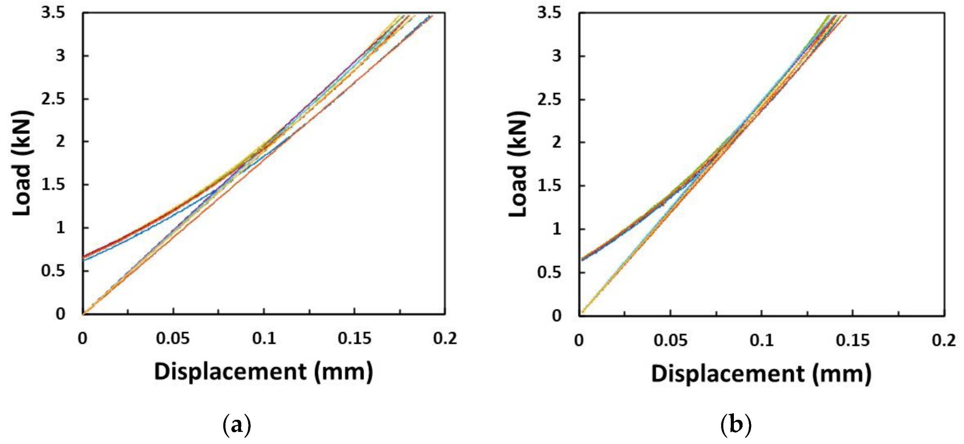
During each compression test there was a settling region and a region of linear response. The settling region is when the specimen and the loading platens would begin shifting prior to generating a stable force across the complete surface of the test specimen. Every specimen displayed a linear region between 2.66 kN and 4.00 kN. The slope of this linear region was determined and used in the determination of the compression modulus. Representative load vs. displacement charts for DM4 and CM3 are shown in
Figure 19. The 5 sequential loadings are shown on each chart and the non-linearity in the lower regions is noted. Also included are the linear trend lines that were used to determine the compression modulus values.
The group of four (4) direct digitally manufactured specimens have an average compression modulus of 12.46 MPa, with a standard deviation of 1.74 MPa. The highest compression modulus of the digitally manufactured specimens was specimen DM3, with an average compression modulus of 13.93 MPa and a standard deviation, based on the 5 repeated loadings, of 0.48 MPa. The lowest compression modulus for the digitally manufactured specimens was specimen DM1, with a compression modulus of 10.20 MPa. The compression molded three (3) specimen group has an average compression modulus of 16.13 MPa and a standard deviation of 0.65 MPa.
4.2. Shear Modulus
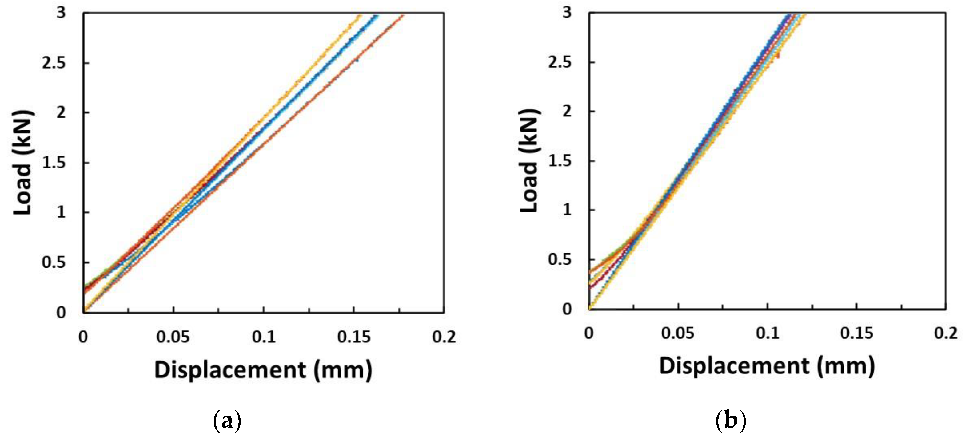
Again, a settling period was observed as the fixturing and test machine loading was initiated. All specimens demonstrated a linear response in the region between 1.33 kN and 2.66 kN. Representative load vs. displacement charts for DM4 and CM3 are shown in
Figure 20. A linear regression was performed in this region to find the slope and from that, determine the shear modulus. The 5 sequential loadings are shown on each chart and the non-linearity in the lower regions is noted.
The four direct digitally manufactured specimens have an average shear modulus of 6.74 MPa with a standard deviation of 1.4 MPa. Within the digitally manufactured specimen group the highest shear modulus is specimen DM4, the specimen with increased placement temperature, with a modulus of 8.69 MPa and a standard deviation of the five sequential loadings of 0.41 MPa. This represents a 24% increase from the specimen that exhibited the lowest shear modulus. The lowest shear modulus is specimen DM1 with a shear modulus of 5.45 MPa. The 3 compression molded specimens have an average shear modulus of 11.44 MPa with a standard deviation of 0.34 MPa.
5. Discussion
It is clear from the results of the compression and shear modulus tests that the digitally manufactured panels do not reach values as high as those of the compression molded, baseline truss core panels. This is not unexpected, as the digitally manufactured panels are in the very early stages of development while the compression molded panels are made by a more traditional, well-developed method, utilizing preimpregnated composite materials. To better understand where further development of the direct digital manufacturing process can be undertaken to improve the Navtruss panels, factors related to commingled tow process conditions, and to tow cross-section geometry, need to be considered.
5.1. Performance Related to Digital Manufacturing Process Variables
Different processing variables were implemented within the 4 digitally produced Navtruss panels. The placement nozzle temperature was set to 290 °C for specimens DM1-DM3 but was increased to 310 °C for specimen DM4 to improve the PET flow and thus, the wetout of the glass fibers and the consolidation. While there were multiple manufacturing differences between DM1, DM2 and DM4, DM4 was manufactured in a virtually identical fashion to DM3, except for the nozzle temperature. The resulting compression moduli for these two specimens are effectively identical; however, the shear modulus for DM4, produced with a 20 °C hotter nozzle temperature, was 8.69 MPa compared to a value of only 6.76 MPa for panel DM3. Given the range of shear moduli measured, this difference is significant and suggests that improved wetout of the core and potentially improved adhesion between the facesheets and the truss core elements resulted from the increased temperature and reduced viscosity. Further increases in nozzle temperature were not attempted as degradation of PETG has been documented at temperatures as low as 320 °C [
42,
43].
The other significant process variation was the introduction of programmed cooling, activated only during transitions at the lower facesheet surface. For specimen DM1, the cooling flow was applied during the placement of the entire panel while for DM2, programmed local cooling was applied. With the application of the programmed cooling, the nozzle outlet temperature remained hotter for the majority of the process for enhanced consolidation. The facesheets and the commingled tow of the core of specimen DM2 were then expected to be better wetout then those of specimen DM1. The test results indicate notably higher compression and shear modulus for the programmed local cooling, with specimen DM2 showing a compression modulus of 13.93 MPa and shear modulus of 6.76 MPa compared to a 10.2 MPa modulus in compression and a 5.45 MPa shear modulus for specimen DM1. These results indicate that the application of programmed local cooling is an effective addition to the direct digital manufacture of the truss core panels.
5.2. Digitally Manufactured Panel Performance Related to Tow Placement Details
It is believed that the primary reason that even the best of the digitally manufactured specimens has a lower modulus than the compression molded Navtruss panels is the inconsistent tow cross-section, particularly within the commingled tow that make up the truss core elements. When placing commingled tow on a tool surface the placement head can apply a consolidation pressure, shaping the tow into a consistent band on the surface, removing voids and wetting out the fibers in the process. However, for these digitally manufactured panels, the truss core is being placed off the tool surface resulting in only limited control of the tow cross-sectional geometry and consolidation force, beyond that which occurs inside the placement nozzle. Previous research has shown that the nozzle outlet size can affect the consolidation within the nozzle [
31,
32]. Those efforts concluded that the void content in the commingled tow markedly increased if the nozzle outlet diameter was 15% larger than the effective diameter of the processed tow. In the case of the current system, the placement nozzle was designed with a diameter of 1.5 mm, based on an estimated commingled tow cross-section equivalent to a 1.4 mm diameter. Thus, with an outlet diameter only 7% larger than the commingled tow, a reasonable degree of consolidation can be expected as the commingled tow passes through the nozzle, even without the nozzle being pressed against a tooling surface. However, even with an expectation of reasonable consolidation as the commingled feedstock passes through the nozzle, the resultant deposited tow geometry can still play a role.
As described earlier, producing the Navtruss core elements with a 3-axis automation system results in the extruded tow exiting the nozzle at a different angle depending on the position within the truss element. This different angle of exit results in different off-the-tool tow geometries, as shown in
Figure 21.
The placement approach used in the digitally manufactured specimens, was an alternating path, left-to-right and then right-to-left for the parallel tows of each truss segment. Thus, on this same angled truss segment facet the effects of the 45° and 135° tow exit, shown schematically in
Figure 11, can be seen. As the tow leaves the nozzle at 45°, moving left-to-right in
Figure 21, it has little spreading and takes on a rod-like cross-section. Conversely, moving right-to-left, the tow leaves the nozzle at 135° resulting in significant spreading and thinning. In
Figure 21 it is also obvious that the geometry of the tow across the flat top of the truss element, where the tow exits the nozzle at 90° is the same, independent of direction of travel. These differences in tow geometry with position in the truss segments compromise the truss core performance. To address this, the use of a multi-axis system of at least 5 axes would be beneficial, as has been previously described for following a complex trapezoidal tool surface [
33]. Thus, through continued process parameter development and the implementation of multi-axis control, it seems that the digitally manufactured Navtruss panels have the potential to demonstrate stiffnesses, in both compression and shear, similar to those produced using the more traditional compression molding of prepreg materials.
6. Conclusions
A direct digital approach to the manufacture of Navtruss core sandwich panels, which radically reduces the amount of tooling required, has been successfully demonstrated. This manufacturing process uses commingled continuous glass fibers and PET fibers as the feedstock from which a high fiber fraction thermoplastic matrix composite can be produced, both on, and off the tool surface. Comparison with a truss core panel, of similar geometry, manufactured by compression molding and fusion joining of the facesheets and truss core elements demonstrates the potential advantages of the direct digital manufacturing approach.
Several Navtruss specimens were manufactured to investigate the effects that direct digital system process modifications have on the resulting panel performance. The best digitally manufactured truss core sandwich panel had a compression modulus that was only 14.6% lower than the average compressive modulus of the baseline compression molded specimens. The shear stiffness of the best preforming digitally manufactured panel was 23% lower than the average shear stiffness of the compression molded specimens. However, as the extruder temperature was increased and controlled cooling was implemented in the direct digital manufacturing process, the composite truss core panel modulus increased by nominally 25% in both compression and shear.
Beyond the potential gains from process parameter improvements while using the current 3-axis system, it seems clear that moving to an automation system with additional axes can offer further benefits through a higher degree of control of both the truss segment shape and the geometry of rigidized tow cross-section. Thus, overall, the results suggest that, with further development, direct digital manufacture of complex truss core structures can be accomplished with radically reduced tooling requirements through off-the-tool surface positioning, rigidization and consolidation of high volume fraction, continuous fiber reinforced thermoplastic matrix composites.
Author Contributions
M.E.B. and D.W.R. were involved in Conceptualization, Methodology, Writing original draft; M.E.B. was involved in Investigation, Formal analysis; D.W.R. was involved in Writing review and editing, Project administration, Funding Acquisition. All authors have read and agreed to the published version of the manuscript.
Funding
This research was funded in part by the STATE OF COLORADO, ADVANCED INDUSTRIES PROGRAMS, POC grant number APP-065686.
Data Availability Statement
Data is contained within the article. The data presented in this study are also available in the MS Thesis of Bourgeois, Mark Elliott, entitled, “Toolless Out of Build Plane Manufacturing of Intricate Continuous Fiber Reinforced Thermoplastic Composites with a 3d Printing System”, Colorado State University ProQuest Dissertations Publishing, 2019. 13904949.
Conflicts of Interest
The authors declare no conflict of interest.
References
- Evertz, R.L. Investigation of Core Closeouts in Fiber-Reinforced Sandwich Laminates. Master’s Thesis, Montana State University, Bozeman, MT, USA, 2000. [Google Scholar]
- Hu, Y.; Li, W.; An, X.; Fan, H. Fabrication and Mechanical Behaviors of Corrugated Lattice Truss Composite Sandwich Panels. Compos. Sci. Technol. 2016, 125, 114–122. [Google Scholar] [CrossRef]
- Lok, T.-S.; Qian-Hua, C. Elastic Stiffness Properties and Behavior of Truss-Core Sandwich Panel. J. Struct. Eng. 2000, 126, 552–559. [Google Scholar] [CrossRef]
- Li, Z.; Zhao, B.; Shao, J.; Liu, S. Deformation Behavior and Mechanical Properties of Periodic Topological Ti Structures Fabricated by Superplastic Forming/Diffusion Bonding. Int. J. Lightweight Mater. Manuf. 2019, 2, 1–30. [Google Scholar] [CrossRef]
- Ge, L.; Zheng, H.; Li, H.; Liu, B.; Su, H.; Fang, D. Compression Behavior of a Novel Sandwich Structure with Bi-directional Corrugated Core. Thin-Walled Struct. 2021, 161, 107413. [Google Scholar] [CrossRef]
- Xin, H.; Mosallam, A.; Liu, Y.; Xiao, Y.; He, J.; Wang, C.; Jiang, Z. Experimental and Numerical Investigation on In-plane Compression and Shear Performance of a Pultruded GFRP Composite Bridge Deck. Compos. Struct. 2017, 180, 914–932. [Google Scholar] [CrossRef]
- Mei, J.; Liu, J.; Liu, J. A Novel Fabrication Method and Mechanical Behavior of All-Composite Tetrahedral Truss Core Sandwich Panel. Compos. Part A 2017, 102, 28–39. [Google Scholar] [CrossRef]
- Ma, L.; Zheng, H.-Y.; Wu, L.-Z. Mechanical Properties and Impulsive Response of 3D-Kagome Truss Core Sandwich Panel. In Proceedings of the 16th International Conference on Composite Materials, Kyoto, Japan, 8–13 July 2007. [Google Scholar]
- Xiong, J.; Ma, L.; Pan, S.; Wu, L.; Papadopoulos, J.; Vaziri, A. Shear and Bending Performance of Carbon Fiber Composite Sandwich Panels with Pyramidal Truss Core. Acta Mater. 2012, 60, 1455–1466. [Google Scholar] [CrossRef]
- George, T.; Deshpande, V.; Wadley, H. Mechanical Response of Carbon Fiber Composite Sandwich Panels with Pyramidal Truss Core. Compos. Part A 2013, 47, 31–40. [Google Scholar] [CrossRef]
- Wadley, H.N.G. Multifunctional Periodic Cellular Metals. Philos. Trans. R. Soc. A 2006, 364, 31–68. [Google Scholar] [CrossRef]
- Liu, S.; Li, Y.; Li, N. A Novel Free-hanging 3D Printing Method for Continuous Carbon Fiber Reinforced Thermoplastic Lattice Truss Core Structures. Mater. Des. 2018, 137, 235–244. [Google Scholar] [CrossRef]
- Li, X.; Wu, L.; Ma, L.; Yan, X. Fabrication and Mechanical Properties of Composite Pyramidal Truss Core Sandwich Panels with Novel Reinforced Frames. Reinf. Plast. Compos. 2016, 35, 1260–1274. [Google Scholar] [CrossRef]
- Li, M.; Wu, L.; Ma, L.; Wang, B.; Guan, Z. Mechanical Response of All-composite Lattice Truss Core Sandwich Structures. Mater. Sci. Technol. 2011, 27, 570–576. [Google Scholar] [CrossRef]
- Xiong, J.; Vaziri, A.; Papadopoulos, J.; Wu, L. Compression and Impact Testing of Two-Layer Composite Pyramidal-Core Sandwich Panels. Compos. Struct. 2012, 94, 793–801. [Google Scholar] [CrossRef]
- Bettini, P.; Alitta, G.; Sala, G.; Di Landro, L. Fused deposition technique for continuous fiber reinforced thermoplastic. J. Mater. Eng. Perform. 2016, 26, 843–848. [Google Scholar] [CrossRef]
- Kvalsvig, A.; Yuan, X.; Potgieter, J.; Cao, P. 3D Printing of Fibre Reinforced Honeycomb Structured Composite Materials. In Proceedings of the 23rd International Conference on Mechatronics and Machine Vision in Practice (M2VIP), Nanjing, China, 28–30 November 2016. [Google Scholar]
- Van Der Klift, F.; Koga, Y.; Todoroki, A.; Ueda, M.; Hirano, Y.; Matsuzaki, R. 3D Printing of Continuous Carbon Fibre Reinforced Thermo-Plastic (CFRTP) tensile test specimens. Open J. Compos. Mater. 2016, 6, 18–27. [Google Scholar] [CrossRef]
- Sugiyama, K.; Matsuzaki, R.; Ueda, M. 3D Printing of Composite Sandwich Structures Using Continuous Fiber and Fiber Tension. Compos. Part A 2018, 113, 114–121. [Google Scholar] [CrossRef]
- Dickson, A.N.; Barry, J.N.; McDonnell, K.A.; Dowling, D.P. Fabrication of Continuous Carbon, Glass, Kevlar Fibre Reinforced Polymer Composite using Additive Manufacturing. Addit. Manuf. 2017, 16, 146–152. [Google Scholar] [CrossRef]
- Justo, J.; Tavara, L.; Garcia-Guzman, L.; Paris, F. Characterization of 3D Printed Long Fibre Reinforced Composites. Compos. Struct. 2018, 185, 537–548. [Google Scholar] [CrossRef]
- Invernizzi, M.; Natale, G.; Levi, M.; Turri, S.; Griffini, G. UV-Assisted 3D Printing of Glass and Carbon Fiber-Reinforced Dual-Cure Polymer Composites. Materials 2016, 9, 583. [Google Scholar] [CrossRef]
- Potter, K.; Kim, B.C.; Weaver, P. Continuous Tow Shearing for Manufacturing Variable Angle Tow Composites. Compos. Part A 2012, 43, 1347–1356. [Google Scholar]
- Radford, D.W.; Hedin, K.M. Fused Deposition Technology Applied to Thermoplastic Matrix Placement and Wetout in Filament Winding. In Proceedings of the 20th International Conference on Composite Materials, Copenhagen, Denmark, 19–24 July 2015. [Google Scholar]
- Rodriguez, P.A.; Bourgeois, M.E.; Radford, D.W. Direct Manufacture of Continuous Fiber Reinforced Composites through a Combination of Fiber Placement and 3D Printing. In Proceedings of the CAMX Conference Proceedings, Anaheim, CA, USA, 27–29 September 2016. [Google Scholar]
- Warlick, K.M. The Effect of Tow Shearing on Reinforcement Positional Fidelity in the Manufacturing of a Continuous Fiber Reinforced Thermoplastic Matrix Composite via Pultrusion-Like Processing of Commingled Feedstock. Master’s Thesis, Colorado State University, Fort Collins, CO, USA, 2017. [Google Scholar]
- Mori, K.; Maeno, T.; Nakagawa, Y. Dieless Forming of carbon fibre reinforced plastic parts using 3D printer. Procedia Eng. 2014, 81, 1595–1600. [Google Scholar] [CrossRef]
- Namiki, M.; Ueda, M.; Todoroki, A.; Hirano, Y.; Matsuzaki, R. 3D printing of continuous fiber reinforced plastic. In Proceedings of the SAMPE Tech Seattle 2014 Conference, Seattle, WA, USA, 2–5 June 2014; p. 6. [Google Scholar]
- Bourgeois, M.E. Toolless Out of Build Plane Manufacturing of Intricate Continuous Fiber Reinforced Thermoplastic Composites with a 3D Printing System. Master’s Thesis, Colorado State University, Fort Collins, CO, USA, 2019. [Google Scholar]
- Rodriguez, P.A. Dynamic Mechanical Analysis for Quality Evaluation of Additively Manufactured Continuous Fiber Reinforced Thermoplastic Matrix Composites Subject to Manufacturing Defects. Master’s Thesis, Colorado State University, Fort Collins, CO, USA, 2019. [Google Scholar]
- Eichenhofer, M.; Wong, J.C.; Ermanni, P. Continuous Lattice Fabrication of Ultra-Lightweight Composite Structures. Addit. Manuf. 2017, 18, 48–57. [Google Scholar] [CrossRef]
- Eichenhofer, M.; Wong, J.C.; Ermanni, P. Exploiting Cyclic Softening in Continuous Lattice Fabrication for the Additive Manufacturing of High Performance Fibre-Reinforced Thermoplastic Composite Materials. Compos. Sci. Technol. 2018, 164, 248–259. [Google Scholar] [CrossRef]
- Bourgeois, M.E.; Radford, D.W. Out of Plane Placement of Tensioned Commingled Roving Creating Truss Sandwich Panels. In Proceedings of the CAMX Conference, Dallas, TX, USA, 15–18 October 2018. [Google Scholar]
- Jushi Compofil Product Sheet, January 2014, Jushi Group Co. Ltd. Available online: https://tp-composites.com/wp-content/uploads/sites/3/2017/01/HELM-AG-Jushi-Hybrid-Yarns.pdf (accessed on 17 October 2022).
- Polystrand Continuous Fiber Reinforced Thermoplastic Tapes & Laminates, Product Selection Guide, Avient. Available online: https://www.avient.com/sites/default/files/2021-11/polystrand-product-selection-guide_0.pdf (accessed on 17 October 2022).
- Rodriguez, P.A.; Radford, D.W. Effect of Applied Consolidation Pressure in Direct Digital Manufacture of Continuous Fiber Reinforced Composites. In Proceedings of the CAMX Conference, Orlando, FL, USA, 12–14 December 2017; pp. 12–14. [Google Scholar]
- Bourgeois, M.E.; Radford, D.W. Consolidation and tow spreading of digitally manufactured continuous fiber reinforced composites from thermoplastic commingled tow using a five-axis extrusion system. J. Compos. Sci. 2021, 5, 73. [Google Scholar] [CrossRef]
- ASTM D792-20; Standard Test Methods for Density and Specific Gravity (Relative Density) of Plastics by Displacement. ASTM International: West Conshohocken, PA, USA, 2020.
- ASTMD3171-15; Standard Test Methods for Constituent Content of Composite Materials. ASTM International: West Conshohocken, PA, USA, 2015.
- ASTMC365-16; Standard Test Methods for Flatwise Compressive Properties of Sandwich Cores. ASTM International: West Conshohocken, PA, USA, 2016.
- ASTMC273-18; Standard Test Methods for Shear Properties of Sandwich Core Materials. ASTM International: West Conshohocken, PA, USA, 2018.
- Samperi, F.; Puglisi, C.; Alicata, R.; Montaudo, G. Thermal Degradation of Poly(ethylene terephthalate) at the Processing Temperature. Polym. Degrad. Stab. 2004, 83, 3–10. [Google Scholar] [CrossRef]
- Latki-Duralek, P.; Dydek, K.; Boczkowska, A. Thermal, Rheological and Mechanical Properties of PETG/rPETG Blends. J. Polym. Environ. 2019, 27, 2600–2606. [Google Scholar] [CrossRef]
Figure 1.
General sandwich panel configuration.
Figure 1.
General sandwich panel configuration.
Figure 2.
Bi-directional Navtruss Core geometry development, (a) 2 Strut Core. (b) 3 Strut Core, (c) 4 Strut Core.
Figure 2.
Bi-directional Navtruss Core geometry development, (a) 2 Strut Core. (b) 3 Strut Core, (c) 4 Strut Core.
Figure 3.
Dual gantry automation platform.
Figure 3.
Dual gantry automation platform.
Figure 4.
Nozzle designs for the composite placement head. (
a) original composite nozzle design; (
b) improved composite nozzle design [
37].
Figure 4.
Nozzle designs for the composite placement head. (
a) original composite nozzle design; (
b) improved composite nozzle design [
37].
Figure 5.
Spring-loaded composite placement end effector.
Figure 5.
Spring-loaded composite placement end effector.
Figure 6.
Manufacturing the second lamina of a Bottom Facesheet [
37].
Figure 6.
Manufacturing the second lamina of a Bottom Facesheet [
37].
Figure 7.
Outer Edge Closure 3D Printed on the Lower Fiber Reinforced Facesheet.
Figure 7.
Outer Edge Closure 3D Printed on the Lower Fiber Reinforced Facesheet.
Figure 8.
Composite Scaffolding in ‘1’ Direction.
Figure 8.
Composite Scaffolding in ‘1’ Direction.
Figure 9.
Placement End Effector Path for Navtruss geometry.
Figure 9.
Placement End Effector Path for Navtruss geometry.
Figure 10.
Navtruss Core Strutt Geometry. (Dimensions in mm).
Figure 10.
Navtruss Core Strutt Geometry. (Dimensions in mm).
Figure 11.
Tow-nozzle exit angle variation.
Figure 11.
Tow-nozzle exit angle variation.
Figure 12.
(a) Composite Truss Segments in ‘2’ Direction, (b) Composite Scaffolding in ‘2’ Direction, (c) Completed Navtruss core prior to addition of the top facesheet.
Figure 12.
(a) Composite Truss Segments in ‘2’ Direction, (b) Composite Scaffolding in ‘2’ Direction, (c) Completed Navtruss core prior to addition of the top facesheet.
Figure 13.
Placement of Top Facesheet onto Core.
Figure 13.
Placement of Top Facesheet onto Core.
Figure 14.
Finished Digitally Manufactured Navtruss Sandwich Panel.
Figure 14.
Finished Digitally Manufactured Navtruss Sandwich Panel.
Figure 15.
Compression Dies, (a) top half with alignment holes, (b) bottom half with dowel pins.
Figure 15.
Compression Dies, (a) top half with alignment holes, (b) bottom half with dowel pins.
Figure 16.
Bonding Sequence for Compression Molded Specimens, (a) core positioning, (b) press bonding of truss segments to the lower facesheet, (c) a view of the joined truss core and facesheet, and (d) the completed baseline Navtruss sandwich panel.
Figure 16.
Bonding Sequence for Compression Molded Specimens, (a) core positioning, (b) press bonding of truss segments to the lower facesheet, (c) a view of the joined truss core and facesheet, and (d) the completed baseline Navtruss sandwich panel.
Figure 17.
Compression Modulus Test Configuration.
Figure 17.
Compression Modulus Test Configuration.
Figure 18.
Sandwich Shear Modulus Testing Configuration, (a) representative specimen geometry showing shear loading configuration, (b) as-tested configuration showing aluminum loading plates bonded to the composite facesheets.
Figure 18.
Sandwich Shear Modulus Testing Configuration, (a) representative specimen geometry showing shear loading configuration, (b) as-tested configuration showing aluminum loading plates bonded to the composite facesheets.
Figure 19.
Load vs. Displacement charts for (a) specimen DM4 and (b) specimen CM3 tested in compression.
Figure 19.
Load vs. Displacement charts for (a) specimen DM4 and (b) specimen CM3 tested in compression.
Figure 20.
Load vs. Displacement charts for (a) specimen DM4 and (b) specimen CM3 tested in shear.
Figure 20.
Load vs. Displacement charts for (a) specimen DM4 and (b) specimen CM3 tested in shear.
Figure 21.
Effect of tow exit angle from the nozzle on truss core segment cross-section.
Figure 21.
Effect of tow exit angle from the nozzle on truss core segment cross-section.
Table 1.
Sandwich Panel Navtruss Core Specimen Information.
Table 1.
Sandwich Panel Navtruss Core Specimen Information.
| Specimen–Description | Core Thickness (mm) | Top Facing Thickness (mm) | Bottom Facing Thickness (mm) | Base (mm) | Width (mm) | Ply Sequence |
|---|
| DM1–Continuous Cooling | 9.93 | 1.69 | 1.35 | 125.5 | 142.0 | [0/90] core [90/0] |
| DM2–Localized Cooling | 10.05 | 1.66 | 1.26 | 125.1 | 141.3 | [0/90] core [90/0] |
| DM3–Thicker Facesheets | 9.65 | 1.86 | 1.54 | 122.7 | 141.9 | [0/90/0] core [0/90/0] |
| DM4–Higher Placement Temperature | 9.65 | 1.94 | 1.63 | 124.1 | 148.7 | [0/90/0] core [0/90/0] |
| CM1 | 8.00 | 1.37 | 1.34 | 130.0 | 130.3 | [90/0/90/0/90] core [90/0/90/0/90] |
| CM2 | 8.95 | 1.42 | 1.42 | 132.8 | 131.1 | [0/90/0/90/0] core [0/90/0/90/0] |
| CM3 | 8.85 | 1.33 | 1.38 | 130.5 | 132.3 | [90/0/90/0/90] core [0/90/0/90/0] |
Table 2.
Compression Modulus by Manufacturing Method.
Table 2.
Compression Modulus by Manufacturing Method.
| Specimen–Description | Compression Modulus (MPa) | Shear Modulus (MPa) |
|---|
| DM1–Continuous Cooling | 10.20 ± 0.34 | 5.45 ± 0.34 |
| DM2–Localized Cooling | 12.00 ± 0.41 | 6.07 ± 0.55 |
| DM3–Thicker Facesheets | 13.93 ± 0.48 | 6.76 ± 0.48 |
| DM4–Higher Placement Temperature | 13.72 ± 0.41 | 8.69 ± 0.41 |
| Average of Digitally manufactured Specimens | 12.46 ± 1.74 | 6.74 ± 1.40 |
| CM1 | 15.47 ± 0.27 | 11.10 ± 0.24 |
| CM2 | 16.77 ± 0.50 | 11.77 ± 0.36 |
| CM3 | 16.16 ± 0.26 | 11.46 ± 0.19 |
| Average of Compression Molded Specimens | 16.13 ± 0.65 | 11.44 ± 0.34 |
| Publisher’s Note: MDPI stays neutral with regard to jurisdictional claims in published maps and institutional affiliations. |
© 2022 by the authors. Licensee MDPI, Basel, Switzerland. This article is an open access article distributed under the terms and conditions of the Creative Commons Attribution (CC BY) license (https://creativecommons.org/licenses/by/4.0/).


