Abstract
This paper provides the results of experimental investigations of the exemplary mini-channel heat exchanger in its application as a condenser and an evaporator in a compressor refrigeration system with propane as a working fluid. The aim of the investigations was to identify the mean heat transfer coefficient of the refrigerant side for the entire operating range of the tested heat exchanger. The experiments covered a mass velocity range from 50 to 160 kg/(m2 × s). The experiments covered a range of liquid subcooling in the condenser from 3 to 15 K and a range of vapour superheating at the outlet of the evaporator from 3 up to 15 K. The experiments on the condenser were conducted at the saturation temperature of 34 °C, and in the case of the evaporator, at the saturation temperature of 8 °C. The average heat transfer coefficients as well as pressure drops in the case of the operation of the tested heat exchanger as an evaporator and condenser were calculated. The heat transfer coefficient was calculated by means of the separated thermal resistance method with the application of the Wilson plot technique. The experiments confirmed the increase in the heat transfer coefficient with the increase in the refrigerant mass flow rate for the tested mini-channel heat exchanger. A dimensionless correlation was proposed for the pressure drop based on the modified Müller-Steinhagen correlation in the case of the operation of the mini-channel heat exchanger as a condenser and as an evaporator.
1. Introduction
The effect of the implementation of the policy that limits the emission of harmful substances into the environment is the necessity to use natural refrigerants in refrigeration systems that do not destroy the atmosphere. The thermokinetic properties of most of the natural refrigerants used in refrigeration systems, heat pumps, or organic Rankine cycles are among the causes of poor heat transfer. This results in the low efficiency of these systems operating with natural fluids such as propane. In addition, natural fluids are flammable, toxic, and explosive. Therefore, from the operational point of view, the key is the solution that allows the minimum amount of working fluid required for the proper operation of the system to be used. The perfect solution, in this case, is the use of mini-channel heat exchangers. Such heat exchangers allow one to achieve high heat transfer coefficients. At the same time, they are very compact and can reduce equipment weight. They also have a high volumetric thermal capacity [1,2]. In addition, the manufacturing costs can be reduced, and the product competitiveness can be improved using aluminium [3].
Mini-channel heat exchangers have become more and more popular. Numerous cases of devices requiring a cooling process, including electronic devices, are a potential field of application for such heat exchangers [4,5]. Mini-channel technology is increasingly used in refrigeration devices, heat pumps, household air conditioning, automotive air-conditioning systems, and power engineering [6,7,8,9]. The mini-channel heat exchanger, in addition to compactness, should have a low weight and a low pressure drop.
Mini-channel heat exchangers are usually used as evaporators and condensers. However, because of the maldistribution of the refrigerant inside the mini-channel heat exchanger, as well as the instability of the refrigerant flow inside the set of mini-channels, the operation of the mini-channel heat exchanger as an evaporator is usually very problematic. There are two major tasks in the thermal design of convective horizontal flow condensers. The first refers to modelling the prediction of heat transfer and pressure drop on either side of the condenser. The second concern is the overall calculation scheme for a condenser analysis with specified input heat-flow parameters and geometry. Hayase [9] modified and adopted a micro-channel heat exchanger from an outdoor unit of a residential air conditioner to use it in an automotive heat pump cycle. The tube-pass design gave priority to the performance under the evaporation condition (heating mode) because of the aim of improving annual efficiency. The performance of mini-channel heat exchangers operating both as condensers and as evaporators was also experimentally investigated by Zanneti et al. [10]. The authors found the performance of the mini-channel heat exchanger to be comparable to that of the finned coil. A mathematical model of the dual-source heat pump was developed by these authors and validated with the experimental data. These authors tested the performance of the heat pump when working with refrigerant R410A and its substitutes: R32, R454B, and R452B. The results showed that the heat pump operating with refrigerant R32 provided the highest cooling and heating capacities as compared with the other refrigerants. The performance of an air/water heat pump using a mini-channel coil as an evaporator instead of a fin-and-tube heat exchanger was tested by García-Cascales et al. [11]. Refrigerant R134a was used in their tests. The results showed that the total amount of refrigerant was lower when using a mini-channel coil as the evaporator, with a charge reduction of up to 11.69%. On the other hand, the efficiency decreased by up to 4.1% when a mini-channel was used. It was pointed out in that paper that because of a decrease in refrigerant charge and also in efficiency, the advantage of replacing a fin-and-tube evaporator with a mini-channel evaporator was not clear. Fernando et al. [12] tested a mini-channel evaporator mounted in a water-to-water heat pump. The heat exchanger was designed similarly to a shell-and-tube-type heat exchanger, with a six-channel tube that had a hydraulic diameter of 1.42 mm, a tube-side heat transfer area of 0.777 m2, and a shell-side heat transfer area of 0.815 m2. The heat transfer coefficients were compared with 14 correlations found in the literature. All of them needed to be adjusted. The experimental heat transfer coefficients were higher than those predicted by many of the correlations. Later [13], the same group investigated the heat transfer in a propane condenser used in a water-to-water heat pump. The condenser was constructed using multiport mini-channel aluminium tubes assembled as a shell-and-tube heat exchanger. The heat transfer areas of the tube side and the shell side of the condenser were 0.941 m2 and 0.985 m2, respectively. The experimental heat transfer coefficients were compared with predictions from correlations found in the literature. The experimental heat transfer coefficients in the different regions were higher than those predicted by the available correlations. The authors found that none of the correlations accurately predicted the experimental heat transfer coefficients in the two-phase section. However, the authors modified Nusselt formulas and two heat transfer correlations from the 1960s in order to predict the experimental heat transfer coefficients within ±15%. Other researchers also tried to develop mathematical models to estimate the optimal amount of refrigerant charge [14,15]. According to Poggi et al. [16], the options favourable to charge reduction were the use of refrigerating systems with secondary refrigeration, the use of direct-expansion-fed evaporators instead of flooded ones, the use of natural refrigerants, and the use of compact exchangers. In [17], the authors analysed the operation of two kinds of mini-channel heat exchangers. A single plate was equipped with a mini-gap 0.1 m long and 0.2 m wide, with a thickness of 0.5 and 1.0 mm or with a set of 50 rectangular mini-channels with a 1 mm × 1 mm cross-section, which results in the same total cross-sectional area. Heat transfer coefficients and pressure drops were compared for both cases as a function of various parameters. One of the authors’ findings was the correlation between the increase in the local heat transfer coefficient with the decrease in the thickness of the mini-gap. The heat transfer coefficient was also reported as being higher for the mini-channel multiport than for the mini-gap of the same cross-section area. The authors indicated the attempt to intensify the heat transfer by modifying the mini-gap surface did not result in a significant increase in the heat transfer coefficient. The authors also highlighted the fact that the pressure drop is relatively small and changes quite slightly. An increase in the pressure drop of 25% was reported when the mini-gap thickness was doubled. A new correlation for the prediction of the heat transfer coefficient was proposed in [18]. The tested heat exchanger was designed as the counter-flow tube-in-tube heat exchanger with a refrigerant R134a flow in the inner tube and hot water flow in the gap between the outer and inner tubes. These authors noticed that the average heat transfer coefficients increased with increasing heat flux while being independent of mass flux. The collected experimental results were used for validation of the existing correlations for the heat transfer coefficient. Among nine of the evaluated heat transfer correlations, four of them filed and five predicted the heat transfer coefficient with less than 25% deviation. The same authors tested the flow boiling pressure drop of R134a in the counter-flow multiport mini-channel heat exchanger [19]. Again, nine correlations were validated by experimental data. The authors found that the Friedel correlation predicted the experimental data better than the other correlations with mean deviations of 12%, whereas other correlations fell within ±35% of the error band. The references for the tested correlations are given in [18,19]. As indicated in [20], the two-phase flow characteristics within micro- or mini-channels may be more sophisticated than conventional macro-channels, and the empirical correlations for one scale may not work for the other one. The authors proposed the dimensional analysis technique to develop appropriate correlations based on experimental investigations of an evaporator and condenser operated with refrigerant R-134a. The heat transfer coefficient for the glycol–water mixture was first obtained using a modified Wilson plot technique. The results were then used in the two-phase flow analysis, and correlations for the refrigerant evaporation and condensation heat transfer were developed. However, the obtained average standard deviation of 51% indicates that more accurate and detailed work needs to be conducted on two-phase flows. The condensation heat transfer of R1234yf and R32 was investigated in [21]. The diameters of horizontal multi-circular mini-channels were 0.81 and 0.49 mm. The proposed heat transfer correlation for circular mini-channels takes into account the effects of forced convection and surface tension. The authors found very good agreement between the predicted and experimental values for R1234yf and R32. The mean deviation for these experimental data was 4%. Additionally, the correlation was tested with R1234yf, R1234ze(E), R32, R134a, R152a, R410A, and R744 used for the flow inside mini-channels with diameters of 0.49–3.48 mm. The results showed that 90% of obtained data points have a mean absolute deviation lower than ±30%. In paper [22], analyses of the performance of an air/water chiller in which the mini-channel condenser is used as a replacement of a conventional fin-and-tube condenser are presented. Results showed that in almost all cases studied, the total mass of the refrigerant is lower by up to 21% using a mini-channel coil as the condenser. Additionally, experimental tests indicated that the mini-channel system behaves slightly worse compared to a conventional fin-and-tube system. However, the numerical analysis shows always slightly better behaviour, with an increase in the EER being up to 6% in a mini-channel condenser.
Based on the literature survey, it is clear that investigations of heat transfer and pressure drop in mini-channel heat exchangers are still required. There is still a clear need for investigations of possible applications of mini-channel heat exchangers as evaporators as, in general, their applications as condensers dominate in the research investigations. In addition, there is a clear need for experimental results for natural working fluids, such as propane, where the demand for the reduction of the charge of the refrigerant in the system is the most important issue due to their exclusivity and flammability. There is still a lack of experimental data for an achievable level of heat transfer in propane mini-channel condensers and evaporators as most of the investigations were carried out for synthetic fluids. The above is motivation for our own investigations of a mini-channel heat exchanger used as an evaporator and condenser with propane as a working fluid. Our own pressure-drop correlation was proposed on the basis of our own large experimental database.
2. Test Stand and Methodology
The design of a highly effective heat exchanger requires accurate surface heat transfer coefficient knowledge. Usually, the average value of this coefficient is taken into consideration. A more accurate prediction of the heat transfer coefficient enables a better configuration of heat exchangers, including optimum flow rates, the lowest pressure drop, and the optimum selection of the heat transfer surface area. The mechanism of heat transfer changes along the heat exchanger accordingly with the changes in the two-phase flow pattern. This causes the significant changes in the local surface heat transfer coefficient along the flow path in the heat exchanger [23]. The measurement of heat flux, fluid temperature, or wall temperature allows for the measurement of the average surface heat transfer coefficient. This can be carried out for both sides of the heat exchanger. The application of a direct method, i.e., the abovementioned measurement approach, is extremely difficult in the case of mini-channel heat exchangers due to a series of technical problems. For this reason, it is clear that for the assessment of the average surface heat transfer coefficient, the application of an indirect measurement method should be proposed. This can be carried out using the Wilson plot technique [24]. In its original form, it was proposed for the measurement of the surface heat transfer coefficient in marine steam condensers or water heaters. Since then, it has undergone several modifications related to advanced measurement techniques and developed statistical numerical methods. The advantage of this approach is the fact that the measurement of the wall temperature inside the heat exchanger is not required. At present, the modified method based on the Wilson plot technique using two coefficients is applied [25].
The average surface heat transfer coefficients on cooling and heating fluid sides are unknown. The method adopts the correlations from both of the surface heat transfer coefficients for a given case of heat transfer. These heat transfer correlations contain unknown constants. Most often, the Wilson method uses linear regression, which allows only two constants to be determined.
The total resistance to heat flow in the evaporator includes: heat transfer on the side of the boiling liquid, thermal conductivity of the material, and heat transfer on the side of cooled air. Total resistance can be called heat transfer resistance. This value can be determined on the basis of measurements of the heat flux absorbed or rejected by the refrigerant and absorbed or released by the air (dependent on the application of the heat exchanger as a condenser or an evaporator) and of the air temperature at the inlet and outlet of the heat exchanger, as well as measurements of the average saturation temperature of the refrigerant. The atmospheric air passing through the heat exchanger located in the air duct is treated as humid air. As the air passes through the heat exchanger, no phase changes occur on the air side.
The measurement of the mass flow rate and the temperature difference of the cooling humid air allow us to determine the amount of heat received by air:
where: —heat flux transferred to the air, —mass flow rate of the humid air measured directly; cp,ha—specific heat of humid air at constant pressure; ΔT—temperature change. The specific heat of humid air cp,ha is calculated as the sum of the specific heat of dry air and specific heat of water vapour. The heat transferred from the refrigerant is calculated from the equation:
in which: —mass flow rate of the refrigerant; Δh—change in specific enthalpy of the refrigerant. On the refrigerant side where the temperature and pressure were measured, the measurements were used to determine the specific enthalpy with use of the NIST database [26].
The test stand for the investigation of mini-channel heat exchangers was built on the basis of an autonomous propane refrigeration system with propylene glycol as the heating fluid in the heat-load and heat-sink subsystems. The air duct was used to allow and maintain the air flow with the required parameters. Figure 1 shows the schematic of the test stand. The investigated mini-channel heat exchanger was assembled in the air-duct section that is shown in Figure 1b. The photograph of the air-duct part is presented on the left-hand side of Figure 2, whereas the right-hand side shows the photograph of the tested heat exchanger. The details of the investigated heat exchanger are presented in Figure 3. The heat exchanger is made of aluminium. It contains 77 tubes arranged in four sections. The four sections have 33, 24, 14, and 6 tubes, respectively. The dimensions of all the tubes are 25 × 2 mm. Each tube contains 13 mini-channels inside. The side length of each square mini-channel is 1.34 mm, except for two marginal channels; see Figure 3. Between the tubes, louvered fins are used in order to enhance the heat transfer area as well as intensify convective heat transfer. The fin heights are 9 mm and the fin pitch is 3 mm; the flat tube pitch is 11 mm. Additionally, the louvered fins have a special shape to enable heat transfer enhancement. The total heat transfer surface area for the refrigerant side is 4.64 m2, and for the air side, it is 22.31 m2. Table 1 presents the detail technical parameters of the tested heat exchanger.
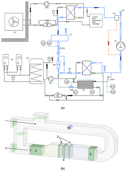
Figure 1.
(a) Schematic diagram of the test stand and propane refrigeration cycle: CG—glycol cooler; KE—electric heaters; MW, Mc, Mn—mass flow meters; PR—evaporator in refrigeration system; PNE, PWE—circulating pumps; OO—oil separator; SK—condenser in refrigeration system; SP—compressor; ZB—safety valve; ZC—liquid receiver; ZE—glycol tank; ZEk—electromagnetic valve; ZR—electronic throttling valve. (b) Schematic diagram of the air duct in test stand: 1—filter, 2—air fan; 3—thermocouple grids; 4—tested heat exchanger; 5—air cooler/air heater; 6—flow meter.
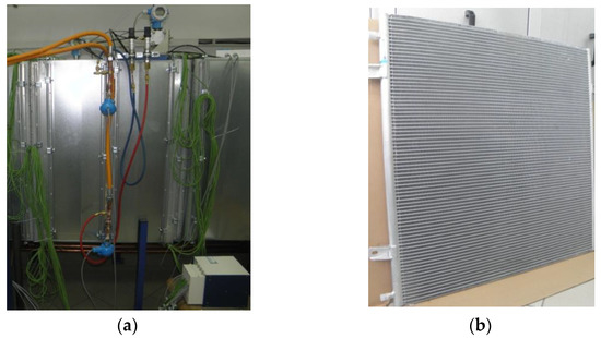
Figure 2.
Test apparatus: (a) overall view of test section in air duct; (b) tested mini-channel heat exchanger.
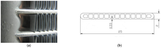
Figure 3.
Details of the investigated mini-channel heat exchanger: (a) louvered fins at the cooling air side; (b) dimensions of the mini-channel pipe section (mm).

Table 1.
Mini-channel heat exchanger: nominal operation parameters.
The test stand was well equipped with a high-class measurement system. The investigations of the heat exchanger were performed according to European standards EN 305:2001, EN 306:2001, and EN 327:2002. The data acquisition system is based on the CompactRIO and the Signal Conditioning Extensions for Instrumentation (SCXI) modular systems, and was used to measure the operating parameters to control the operation of the pumps, fans, glycol cooler, etc. On the refrigerant side, the Pt100 transducers were used for temperature measurements. The temperature of the humid air in the duct was measured in front of and behind the tested heat exchanger using K-type thermocouples placed in the mesh of 5 × 5 test points. In order to reduce the flow disturbances, the mesh was made of 0.5 mm wire. The temperature measurements were conducted 0.3 m in front of and behind the heat exchanger. Pressure was measured using Wika IS20 (WIKA Alexander Wiegand SE & Co. KG, Alexander-Wiegand-Straße 30, 63911 Klingenberg/Germany) transducers with a 4–20 mA output current. In order to reduce the measurement error, the measurement system was calibrated. Calibration of the pressure channels was performed by means of a high-class pressure transducer with the accuracy of 0.075% in the measurement range. For calibration of the temperature measurement channels, the ultra-thermostat was used. The applied ultra-thermostat provides an accuracy of 0.02 K. Calibration was performed in the range of −25 °C to +60 °C. On the basis of the obtained results, appropriate corrections were determined and then introduced to the measurement system. The average uncertainty of the entire measurement path of temperature is ±0.15 K.
The mass flow of working fluids was measured using Endress+Hauser Promass 40E series mass flow meters. The measurement uncertainty of the mass flow for liquid is ±0.5% of the actual flow meter measurement. During the test of the heat exchanger, thermodynamic parameters were measured at the refrigerant side and at the air side. On the basis of the above-presented measurement uncertainties, the average measurement error of the heat flux calculated with the total differential method for the tested heat exchangers over the entire measurement range was approx. 5.5%.
3. Results
3.1. Investigations of Mini-Channel Condenser
The exchanger was fed with the refrigerant vapour from the cooling system. For the purpose of testing the condenser, a measurement system was prepared, which is presented in Figure 4. During the tests, the temperature of the inlet air and the mass flow rate of air in the air duct were kept constant, and the pressure of propane condensation in the tested exchanger was kept constant at a level of 11.5 bar, which corresponds to the saturation temperature of 34 °C. The variable parameter was the mass flow rate of propane flowing through the exchanger, which resulted in variable liquid subcooling at the outlet of the condenser.
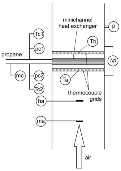
Figure 4.
Heat exchanger section of the test stand: —refrigerant mass flow meter; —air mass flow meter; ha—hygrometer; Ta, Tb—thermocouple grids at inlet and outlet, respectively; p—pressure transducer; Δp—differential pressure sensor; Tc1, Tc2—thermocouples at inlet and outlet of refrigerant side, respectively; pc1, pc2—pressure transducers at inlet and outlet of refrigerant side, respectively.
During the tests, the air velocity was controlled by a fan in the air duct. The mass flow rate of the refrigerant was fixed. The Dittus–Boelter equation was used to determine the heat transfer coefficient for the air side:
where: C—constant, to be determined; Re—Reynolds number; and Pr—Prandtl number. Subscript o refers to the outer side of the heat exchanger. The temperature distribution of air for an exemplary measurement point is given in Table 2.
Table 2.
Exemplary temperature distribution of air for investigations of condenser.
The experimental results were used for the determination of constant Co. For the investigation of the heat exchanger operating as a condenser, the constant Co = 0.1062 was obtained. Additionally, the average heat transfer coefficient is referred to as the outer side of the heat exchanger, namely, the air side. It must be pointed out that a specific perforation of the louvered fins is used for enhancement of the heat transfer.
Once the average heat transfer coefficient for the outer side of the heat exchanger is obtained, the measurement of the heat transfer coefficient for the inner side is possible. This can be performed through separation of the thermal resistances. The overall heat transfer coefficient includes the convective heat transfer on the air side, thermal conduction resistance of the mini-channel material, and convective heat transfer on the refrigerant side. For the measurement of the air temperature in front of and behind the investigated heat exchanger, the heat flux and saturation temperature are sufficient to determine the overall resistance of heat transfer according to the formula:
where: Ao—heat transfer surface area, k—overall heat transfer coefficient; ΔTm—mean temperature difference; —heat flux. Since the local heat transfer coefficient for condensing the refrigerant depends on the two-phase flow pattern, the values are expected to change significantly along the flow path in the heat exchanger. These changes might be significant at the two-phase region especially. Using Equation (5), the average surface heat transfer coefficient can be determined:
where: αi—average surface heat transfer coefficient, Awi—condensation-side heat transfer surface area, Awa—air-side heat transfer surface area, Co—constant, and Rt—thermal conduction heat transfer resistance of the wall material. Using Equation (3), it can be obtained:
where: λ—thermal conductivity of air, Dh—hydraulic diameter, Reo—Reynolds number, and Pro—Prandtl number.
Despite the fact that efforts were made to keep the air parameters unchanged at the inlet to the air duct, minor fluctuations in air temperature, as well as a change in the amount of refrigerant flow rate, were observed. As a result, different levels of liquid subcooling at the condenser outlet were reported. The measurement results are further grouped according to the level of the refrigerant liquid subcooling ΔTc at the condenser outlet, which varied from 3 K up to 15 K. They are presented in Figure 5, Figure 6 and Figure 7.
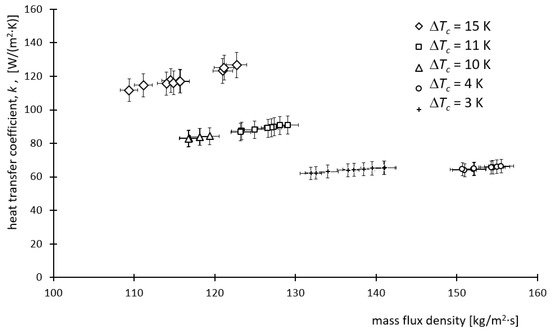
Figure 5.
Dependence of the overall heat transfer coefficient k on refrigerant mass flux density for various subcoolings ΔTc.
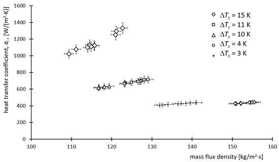
Figure 6.
Local heat transfer coefficient αi for condensing refrigerant side against refrigerant mass flux density for various subcoolings ΔTc.
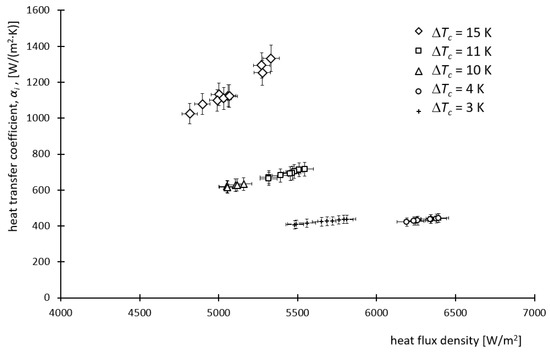
Figure 7.
Convective heat transfer coefficient αi for refrigerant side against heat flux density for various subcoolings ΔTc.
It is seen in Figure 5 that with the increase in refrigerant mass flux density, both heat transfer parameters, i.e., the overall heat transfer coefficient k and surface heat transfer coefficient αi, increase. Additionally, both parameters are directly proportional to the liquid subcooling ΔTc. For example, for a refrigerant subcooling of 3–4 K, the overall heat transfer coefficient k was achieved at the level of approx. 60 W/(m2 × K) and the surface heat transfer coefficient αi, approx. 400 W/(m2 × K). However, for the liquid subcooling ΔTc = 15 K, k ≈ 120 W/(m2 × K) and αi ≈ 1200 W/(m2 × K) were obtained. Higher liquid subcoolings were reported for lower values of mass flux densities. In most of the cases, a higher liquid subcooling is not desirable. The exception is the system where a two-phase injector is used as a substitute for the mechanical liquid pumps in ejector refrigeration systems [27]. The experimental data for such systems, especially in terms of natural refrigerants excluding CO2, are still limited; therefore, the selection or design of a mini-channel heat exchanger can be thought of as a complex task.
The flow resistances in the investigated mini-channel condenser increase as long as the refrigerant mass flux density increases. As expected, this leads to an increase in the pressure drop. A linear relationship between the pressure drop and mass flux density is shown in Figure 8. The pressure drop prediction in the tested heat exchangers is based on the modified Müller-Steinhagen correlation [28]. Therefore, the pressure drop in the investigated heat exchanger can be estimated as:
where: Δp—pressure drop of the two-phase flow; β—two-phase factor; and ΔpVO—pressure drop of the vapour-phase flow only.
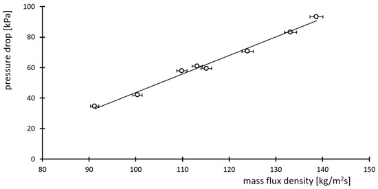
Figure 8.
Dependence of pressure drop of condensing refrigerant on the mass flux density.
The coefficient β used in Equation (7) can be expressed as [29]:
where Cf is the resistance coefficient and ξ is the coefficient defined by Equation (9):
where: G—mass flux density; µ′, µ″—dynamic viscosities of liquid and vapour, respectively; and ρ′, ρ″—densities of liquid and vapour, respectively. Using experimental data obtained for the mini-channel propane condenser, the following correlation for coefficient Cf was proposed:
where ReV is the Reynolds number for the vapour-only flow. The coefficient of determination R2 = 0.832 was obtained. Figure 9 shows the comparison between the proposed correlation and experimental results.
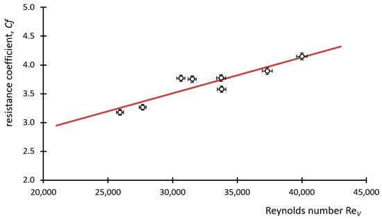
Figure 9.
Relationship between the coefficient Cf of two-phase flow and Reynolds number.
3.2. Investigations of Mini-Channel Evaporator
During the investigation of the mini-channel heat exchanger working as an evaporator (air cooler), the exchanger was fed with a liquid refrigerant from a propane installation. The schematic diagram of the tested evaporator part is shown in Figure 10. The tested mini-channel evaporator was supplied with the refrigerant through an electronic throttle valve, which allowed for the very smooth control of the refrigerant superheating. The vapour pressure was kept at 0.6 MPa, which corresponds to a saturation temperature of +8 °C. The refrigerant mass flow varied in the range of 120—200 kg/h. In the tests, the variable parameters were the steam superheating at the outlet from the exchanger and the propane mass flow.
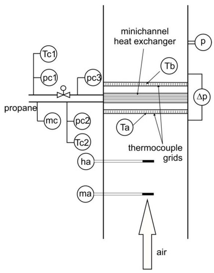
Figure 10.
Heat exchanger section of the test stand: —refrigerant mass flow meter; —air mass flow meter; ha—hygrometer; Ta, Tb—thermocouple grids at inlet and outlet, respectively; p—pressure transducer; Δp—differential pressure sensor; Tc1, pc1—temperature and pressure measurement probes before throttling; t—heat exchanger inlet; Tc2, pc2—temperature and pressure measurement probes at heat exchanger; pc3—pressure measurement at heat exchanger inlet.
For the flow boiling, the following heat transfer correlation was applied:
in which the Kutateladze number is defined as:
Thus, the surface heat transfer coefficient on the refrigerant side can be written as:
where Ci is constant and:
In Equations (11)–(14), λ is the thermal conductivity of air; Dhi is the hydraulic diameter; Rei is the Reynolds number; Ku is the Kutateladze number; ρ′, ρ″ are the saturated liquid and saturated vapour densities, respectively; hfg is the specific enthalpy of vaporisation; and w” is the vapour velocity.
Analogically, as for the condenser, the temperature distribution of air for an exemplary measurement point is given in Table 3.
Table 3.
Exemplary temperature distributions of air for investigations of evaporator.
Results of the measurements of the overall heat transfer coefficient k are shown in Figure 11. This coefficient takes values in the range of 30–60 W/(m2 × K). Analogically, for the condenser investigations, higher heat transfer coefficients are reported for higher mass flux densities. The average value of the overall heat transfer coefficient results in the special geometry of the louvered fins on the air side of the heat exchanger.
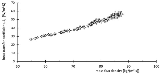
Figure 11.
Experimental values of heat transfer coefficient k against the refrigerant mass flux density.
Once the overall heat transfer coefficient k was obtained, the mean heat transfer coefficient αi was obtained. It must be pointed out that the heat transfer coefficient αi also covers the superheated vapour area. Results of the obtained αi are given in Figure 12.
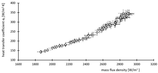
Figure 12.
Average surface heat transfer coefficient αi against heat flux density.
As it is seen in Figure 12, there is a linear relationship between the heat flux density and average surface heat transfer coefficient. An increase in heat flux density leads to an increase in the heat transfer coefficient αi. The latter varies in the range of 150–350 W/(m2 × K). The obtained results cover the entire heat exchanger, including the zone where the refrigerant vapour is superheated. It must be pointed out that for the region of sensible heat transfer, i.e., the vapour superheating region, the heat transfer is significantly lower in comparison with the phase-change region. This effect is presented in Figure 13, in which the influence of vapour superheating is demonstrated. However, it is not possible to indicate the percentage of the area of the evaporation region and superheating region based on the applied measurement approach. Based on the obtained results of the average surface heat transfer coefficient, the presence of the superheating region seems to not be negligible. It can be postulated that for high vapour superheating, a forced convection would be the dominant heat transfer mechanism.
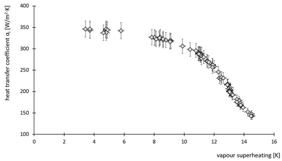
Figure 13.
Average surface heat transfer coefficient αi against vapour superheating.
The experimental results were also used for the analysis of the pressure drop produced by the heat exchanger. A similar method as for the condenser was applied to determine the flow resistance coefficient. Results are presented in Figure 14 and Figure 15.
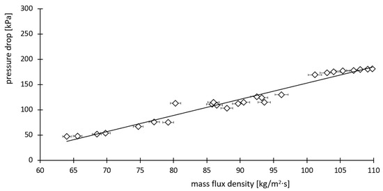
Figure 14.
Relationship between the pressure drop of evaporating refrigerant and mass flux density.
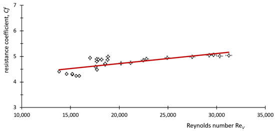
Figure 15.
Dependence of flow resistance coefficient of two-phase flow on Reynolds number for vapour phase.
It is seen in Figure 15 that the linear relationship between the flow resistance coefficient Cf and Reynolds number exists. It is also seen that the slope is small in magnitude; therefore, Cf is changing slowly relative to Re and the line is nearly horizontal. The following correlation can be proposed for this case:
where ReV is the Reynolds number for the vapour-only flow.
The coefficient of determination for Equation (15) is R2 = 0.555. This value can be considered to be smaller than in the case of the condenser. However, it should be pointed out that the correlation was developed on the basis of several thousand measurement points which were averaged. As can be seen in Figure 14, in the range of smaller Reynolds numbers, Re < 20,000, the deviation of the resistance coefficient value is slightly larger than for Reynolds numbers > 20,000.
4. Conclusions
The paper describes the test stand designed for comprehensive tests of mini-channel heat exchangers using propane as a working fluid. The test stand enables the experiments of the application of the mini-channel heat exchangers as air-cooled condensers and evaporators (air coolers). The following conclusions have been drawn on the basis of the obtained results:
- The stable operation of the tested mini-channel heat exchanger as an evaporator was proved. No instabilities of operation of this heat exchanger were observed that could result in the deterioration of heat transfer under the conditions of operation with a changed mass flow rate or vapour superheating at the outlet of the evaporator.
- The investigation results confirmed there is an increase in the mean heat transfer coefficient alongside the increase in the refrigerant mass flow rate for the tested mini-channel condenser and evaporator. It should be also taken into account that the heat transfer coefficient was averaged and refers to the entire heat exchanger, which covers the liquid subcooling region (in the condenser) as well as the vapour superheating region (in the evaporator).
- Liquid subcooling causes a significant increase in both the overall and surface heat transfer coefficients for the tested mini-channel condenser; an increase in liquid subcooling from 3–4 K up to 15 K causes a twofold increase in the overall heat transfer coefficient and approx. a triple increase in the surface heat transfer coefficient.
- The vapour superheating at the outlet of the tested mini-channel evaporator causes a significant reduction in the surface heat transfer coefficient, i.e., a change in the vapour superheating from 3 K to 15 K causes approx. a 60% reduction in the surface heat transfer coefficient.
- The modified Müller-Steinhagen pressure-drop correlation may be effectively applied for calculation of the frictional pressure drop in the tested mini-channel condenser and evaporator. We proposed our own correlations for the friction coefficient for the propane mini-channel condenser and evaporator.
- There is a clear need for further research on the thermal performance of the mini-channel condensers and evaporators of different geometries and flow configurations in order to establish an experimentally based methodology of prediction for average heat transfer coefficients, especially with propane as a working fluid.
Author Contributions
Conceptualization, D.B. and K.Ś.; methodology, D.B.; software, K.Ś.; validation, J.G., A.D. and M.Ł.; formal analysis, H.Z.; investigation, J.G.; resources, H.Z.; data curation, A.Ł.; writing—original draft preparation, K.Ś.; writing—review and editing, D.B. and K.Ś; visualization, J.G.; supervision, D.B.; project administration, D.B.; funding acquisition, D.B. All authors have read and agreed to the published version of the manuscript.
Funding
The research results presented in the paper were conducted and obtained within the statutory activities of WZ/WM-IIM/1/2020, financed by the Ministry of Education and Science.
Data Availability Statement
The data presented in this study are available on request from the corresponding author.
Conflicts of Interest
The authors declare no conflict of interest.
References
- Cavallini, A.; Del Col, D.; Rossetto, L. Heat transfer and pressure drop of natural refrigerants in minichannels (low charge equipment). Int. J. Refrig. 2013, 36, 287–300. [Google Scholar] [CrossRef]
- Del Col, D.; Bortolato, M.; Bortolin, S. Comprehensive experimental investigation of two-phase heat transfer and pressure drop with propane in a minichannel. Int. J. Refrig. 2014, 47, 66–84. [Google Scholar] [CrossRef]
- Bhosale, S.; Acharya, A.R. Review on Applications of Micro Channel Heat Exchanger. Int. Res. J. Eng. Technol. 2020, 7, 5326–5329. [Google Scholar]
- Sanap, O.; Kulkarni, P.; Holkar, S.; Chaudhari, P.; Dholkawala, M.S. Heat Enhancement in Mini Channel Heat Exchanger using Software Analysis Method. Int. J. Eng. Res. Appl. 2020, 10, 1–7. [Google Scholar]
- Mohamed, M.; Abd El-Baky, M.A. Air Cooling of Mini-Channel Heat Sink in Electronic Devices. J. Electron. Cool. Therm. Control. 2013, 3, 33063. [Google Scholar] [CrossRef]
- Ahammed, N.; Asirvatham, L.; Wongwises, S. Thermoelectric cooling of electronic devices with nanofluid in a multiport minichannel heat exchanger. Exp. Therm. Fluid Sci. 2016, 74, 81–90. [Google Scholar] [CrossRef]
- Thakur, N.; Inamdar, A.; Pal, D.; Mohite, A. Heat Exchangers in Aerospace Applications. Int. Res. J. Eng. Technol. 2021, 8, 266–274. [Google Scholar]
- Arteconi, A.; Giuliani, G.; Tartuferi, M.; Polonara, F. Characterization of a mini-channel heat exchanger for a heat pump system. J. Phys. Conf. Ser. 2013, 501, 012023. [Google Scholar] [CrossRef]
- Hayase, G. Study of Micro Channel Heat Exchanger for Automotive Heat Pump System. In Proceedings of the International Refrigeration and Air Conditioning Conference, West Lafayette, IN, USA, 9–12 July 2018; Available online: https://docs.lib.purdue.edu/iracc/1864 (accessed on 7 September 2022).
- Zanetti, E.; Azzolin, M.; Bortolin, S.; Busato, G.; Del Col, D. Experimental data and modelling of a dual source reversible heat pump equipped with a minichannels evaporator. Therm. Sci. Eng. Prog. 2022, 35, 101471. [Google Scholar] [CrossRef]
- García-Cascales, J.R.; Illán-Gómez, F.; Hidalgo-Mompeán, F.; Ramírez-Rivera, F.A.; Ramírez-Basalo, M.A. Performance comparison of an air/water heat pump using a minichannel coil as evaporator in replacement of a fin-and-tube heat exchanger. Int. J. Refrig. 2017, 74, 560–575. [Google Scholar] [CrossRef]
- Fernando, P.; Bjorn, P.; Ameel, T.; Lundqvist, P.; Granryd, E. A minichannel aluminium tube heat exchanger—Part II: Evaporator performance with propane. Int. J. Refrig. 2008, 31, 681–695. [Google Scholar] [CrossRef]
- Fernando, P.; Bjorn, P.; Ameel, T.; Lundqvist, P.; Granryd, E. A minichannel aluminium tube heat exchanger—Part III: Condenser performance with propane. Int. J. Refrig. 2008, 31, 696–708. [Google Scholar] [CrossRef]
- Salama, A.I.A. Heat exchanger network synthesis based on minimum rule variations. Appl. Therm. Eng. 2008, 28, 1234–1249. [Google Scholar] [CrossRef]
- Xu, Y.-C.; Chen, Q. Minimization of mass for heat exchanger networks in spacecrafts based on the entransy dissipation theory. Int. J. Heat Mass Transf. 2012, 55, 5148–5156. [Google Scholar] [CrossRef]
- Poggi, F.; Macchi-Tejeda, H.; Leducq, D.; Bontemps, A. Refrigerant charge in refrigerating systems and strategies of charge reduction. Int. J. Refrig. 2008, 31, 353–370. [Google Scholar] [CrossRef]
- Klugmann, M.; Dąbrowski, P.; Mikielewicz, D. Flow distribution and heat transfer in minigap and minichannel heat exchangers during flow boiling. Appl. Therm. Eng. 2020, 181, 116034. [Google Scholar] [CrossRef]
- Kaew-On, J.; Sakamatapan, K.; Wongwises, S. Flow boiling heat transfer of R134a in the multiport minichannel heat exchangers. Exp. Therm. Fluid Sci. 2011, 35, 364–374. [Google Scholar] [CrossRef]
- Kaew-On, J.; Sakamatapan, K.; Wongwises, S. Flow boiling pressure drop of R134a in the counter flow multiport minichannel heat exchangers. Exp. Therm. Fluid Sci. 2012, 36, 107–117. [Google Scholar] [CrossRef]
- Jokar, A.; Hosni, M.; Eckels, S. Dimensional analysis on the evaporation and condensation of refrigerant R-134a in minichannel plate heat exchangers. Appl. Therm. Eng. 2006, 26, 2287–2300. [Google Scholar] [CrossRef]
- Jige, D.; Mikajiri, N.; Nobunaga, M.; Inoue, N. Condensation heat transfer of pure refrigerants R1234yf and R32 inside multiple circular minichannels. Int. J. Heat Mass Transf. 2022, 195, 123146. [Google Scholar] [CrossRef]
- Illán-Gómez, F.; García-Cascales, J.R.; Hidalgo-Mompeán, F.; López-Belchí, L. Experimental assessment of the replacement of a conventional fin-and-tube condenser by a minichannel heat exchanger in an air/water chiller for residential air conditioning. Energy Build. 2017, 144, 104–116. [Google Scholar] [CrossRef]
- Kandlikar, S.G.; Shoji, M.; Dhir, V.K. Handbook of Phase Change: Boling and Condensation; CRC Press: Boca Raton, FL, USA, 1999. [Google Scholar]
- Fernandez-Seara, J.; Uhia, F.; Sieres, J.; Campo, A. A general review of the Wilson plot method and its modifications to determine convection coefficients in heat exchange devices. Appl. Therm. Eng. 2007, 27, 2745–2757. [Google Scholar] [CrossRef]
- Briggs, D.E.; Young, E.H. Modified Wilson Plot Techniques for Obtaining Heat Transfer Correlations for Shell and Tube Heat Exchangers. Chem. Eng. Prog. Symp. 1969, 92, 35–45. [Google Scholar]
- Lemmon, E.W.; Huber, M.L.; McLinden, M.O. NIST Standard Reference Database 23: Reference Fluid Thermodynamic and Transport Properties-REFPROP, Version 9.1; National Institute of Standards and Technology, Standard Reference Data Program: Gaithersburg, MD, USA, 2013.
- Śmierciew, K.; Butrymowicz, D.; Kwidziński, R.; Przybyliński, T. Analysis of application of two-phase injector in ejector refrigeration systems for isobutane. Appl. Therm. Eng. 2015, 78, 630–639. [Google Scholar] [CrossRef]
- Müller-Steinhagen, H.; Heck, K. A simple friction pressure drop correlation for two-phase flow in pipes. Chem. Eng. Process. Process Intensif. 1986, 20, 297–308. [Google Scholar] [CrossRef]
- Zalewski, W. Thermal-Flow Processes in Evaporative Heat Exchangers; Monograph No. 139; Publishers of Krakow University of Technology: Krakow, Poland, 1992. [Google Scholar]


Publisher’s Note: MDPI stays neutral with regard to jurisdictional claims in published maps and institutional affiliations. |
© 2022 by the authors. Licensee MDPI, Basel, Switzerland. This article is an open access article distributed under the terms and conditions of the Creative Commons Attribution (CC BY) license (https://creativecommons.org/licenses/by/4.0/).