Skip Content
You are currently on the new version of our website. Access the old version .
EnergiesEnergies
  • Feature Paper
  • Article
  • Open Access

6 April 2017

Semiconductor Devices in Solid-State/Hybrid Circuit Breakers: Current Status and Future Trends

,
,
,
and
1
Department of Electrical and Electronic Engineering, The University of Nottingham, Nottingham NG7 2RD, UK
2
Department of Electrical and Electronic Engineering, The University of Mines and Technology, Tarkwa, Ghana
*
Author to whom correspondence should be addressed.
This article belongs to the Special Issue Semiconductor Power Devices

Abstract

Circuit breakers (CBs) are the main protection devices for both alternating current (AC) and direct current (DC) power systems, ranging from tens of watts up to megawatts. This paper reviews the current status for solid-state circuit breakers (SSCBs) as well as hybrid circuit breakers (HCBs) with semiconductor power devices. A few novel SSCB and HCB concepts are described in this paper, including advantage and limitation discussions of wide-band-gap (WBG) devices in basic SSCB/HCB configuration by simulation and 360 V/150 A experimental verifications. Novel SSCB/HCB configurations combining ultra-fast switching and high efficiency at normal operation are proposed. Different types of power devices are installed in these circuit breakers to achieve adequate performance. Challenges and future trends of semiconductor power devices in SSCB/HCB with different voltage/power levels and special performance requirements are clarified.

1. Introduction

In electric transmission, distribution systems and industrial fields, sensitive equipment must be protected from long-period overload and instant short-circuit conditions. Among all protection devices, the circuit breaker (CB) is the most efficient. With the rapid growth of the capacity of electric systems, the maximum perspective fault currents have become higher than at any time in the past, which requires even higher ultimate short-circuit breaking capacity for CBs, associated with ultra-fast breaking capability, to avoid misinterruption of faults in both alternating current (AC) or direct current (DC) systems. Otherwise the cable or terminal equipment might be destroyed [1].
For hierarchical low-voltage power networks, one main mechanical circuit breaker (MCB) works together with several molded-case circuit breakers (MCCB). The main MCB should continue its service in a certain degree of downstream fault condition with current-limiting (CL) behavior and wait for the MCCB to clear the fault. With short-circuit faults the particular MCCB must disconnect as soon as possible to avoid the effects of failure to do so [2].
For higher power applications with either high current, high voltage, or both, e.g., high-voltage direct-current (HVDC) or medium-voltage direct-current (MVDC) systems, natural zero-voltage crossing does not exist anymore because of their unipolarity, therefore causing more serious problems for high power DC networks with MCBs. Applications with sensitive loads such as computer servers or medical treatment equipment necessitate either ultra-fast fault clearance or instant current limitation ability for CBs. The basic requirements of present and future circuit breakers should be:
(i)
“Fully controllable”: The conducting and breaking of CBs should be fully controllable either by automatic mechanical tripping or digital controls;
(ii)
“Higher switching speed”: CBs should break the fault current as soon as they could to avoid huge fault current destroying end equipment;
(iii)
“Low conduction loss”: CBs should maintain the same scale of conduction loss as previous MCBs, therefore the efficiency for normal operation must be appropriate;
(iv)
“Smaller arcing”: For both DC and AC applications, electric arcing should be avoided or suppressed to retain long lifetime of the CB itself, and at the same time, ensure definitized tripping of the CB system.
In recent times, power semiconductor devices have been applied expansively in circuit breakers as they are practically controlled switches [2]. The object called ‘solid-state circuit breaker (SSCB)’, is the CB with pure semiconductor devices [3,4]. With silicon-based power devices, SSCBs offer tripping speeds of up to hundreds of microseconds. Furthermore, as there is no mechanical components or parts, neither contact erosion, electric arc, nor strong mechanical shake exists. On the other hand, SSCBs present several disadvantages: (a) the unignorable on-state resistance means significant power loss, which could cause critical heat and lower system efficiency; (b) semiconductors are sensitive to transit over-voltage and heat-causing over-currents, which makes them a natural weakness of the whole electric system and needs more self-protection technology; (c) the costs and physical volume of semiconductor devices is no doubt a limitation for further development; (d) bidirectional semiconductor devices [5,6] are needed for bidirectional applications (e.g., AC or power regeneration fields), thus doubling the number of devices, redoubling the costs and complexity of control, and reducing reliability. As a result, pure SSCBs are now used in low-power low-voltage (e.g., 24 V) systems, where switching speed must be guaranteed, and power loss is not a priority. In future, by applying next-generation wide bandgap devices e.g., silicon carbide (SiC) or gallium nitride (GaN), the performance of SSCBs may be improved because of lower power loss, higher junction temperature, better avalanche breakdown capability and so on.
Another main category of CB with semiconductor devices is actually a combination of SSCB and MCB in a proper way to configure a new family, which is named “hybrid circuit breaker (HCB)” [7]. Taking the benefits of both sides, HCBs display lower power losses than SSCBs and higher switching speeds than MCBs.
This paper discusses current status and future trends of semiconductor devices in SSCBs and HCBs. In Section 2, a review of the previous and current status of SSCB and HCB is given with comparisons and discussions. In Section 3, basic SSCB and HCB configurations are investigated with novel control methods for fast switching and current limiting. Limitations of basic configurations are described. Three novel circuit breaker configurations with features of fast switching and acceptable normal-mode power loss are proposed afterwards. A discussion of semiconductor devices in CB applications is put forward as a guideline for further design. Future trends and challenges are briefly discussed in Section 4. The conclusions of this paper are gathered and sublimated in Section 5.

2. Review of Solid-State/Hybrid Circuit Breakers

As already discussed in Section 1, a circuit breaker should work properly to either switch fast enough or be able to depress the fault current [8]. It is clear that the configuration of a circuit breaker will vary with different applications, therefore there is no universal circuit breaker design concept. In the review part, CBs for higher-voltage applications e.g., HVDC or MVDC which requires series-connected semiconductors are simplified as one single device. Dynamic voltage balancing may be achieved by gate control, paralleled resistors or arrestors.

2.1. Fast-Breaking Mechanical Devices

Fast mechanical switches (FMSs) are used in a modern MCB [9,10,11]. The FMS could trip and clear faults in hundreds of microseconds (usually within 10 ms), which makes it possible to interrupt a low-frequency AC current of 50 Hz or 60 Hz before it goes up to the anticipated maximum value [12,13]. Reference [14] describes a brief operation guide of MCCBs. The arcing phenomena of MCBs are presented in [15,16]. FMS is the fundamental of mechanical part of HCBs, which restricts the tripping speed of the CB system.

2.2. Basic Solid-State/Hybrid Circuit Breakers

As shown in Figure 1, a Japanese team introduced in 1994 a current-limiting circuit breaker (CL-CB) for low-voltage power systems [12]. The CL-CB consists of high-speed mechanical switch, solid-state switch e.g., gate turn-off thyristor (GTO), snubber circuit and voltage protection element e.g., zinc oxide (ZnO) arrester. This is considered a common topology of CL-CB. After twenty-three years of progress, solid-state switches are changing to insulated-gate bipolar transistors (IGBTs) and SiC metal-oxide-semiconductor field-effect transistor (MOSFETs); and mechanical switches are becoming faster and faster.
Figure 1. An HCB for 400 V class electric power systems in 1994.

2.3. CL-CBs with Switched Resistive Components

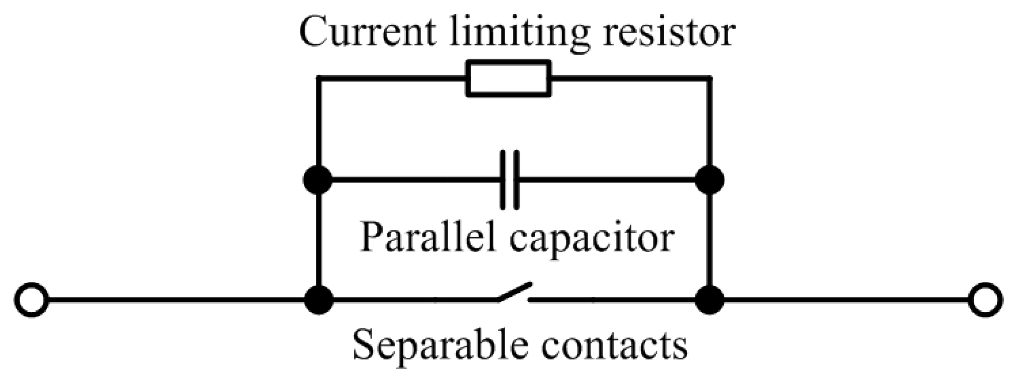
2.3.1. CL-CBs with Ordinary Resistors

In 1980, the United States Electric Power Research Institute (EPRI) had proposed a CL method in which semiconductor devices are not used, as shown in Figure 2. Only a constant-value resistor is used for current limiting [17]. A paralleled capacitor is an additional component which avoids arcing of the contacts.
Figure 2. EPRI switched impedance CB with resistor and mechanical switch in 1980.
As shown in Figure 3, a high speed switch (HSS) with a trip time less than 1 ms achieved by installing an electromagnetic repulsion mechanism and a spring mechanism was proposed [18]. A CL component was also proposed in [18], consisting of HSS, a CL resistor and a counter pulse circuit. When a fault occurs, the fault current could be enforced to zero by adding a counter pulse current. As in Figure 3, a current limiting device with resistive elements was put forward in [19] for medium-voltage distribution network.
Figure 3. CL device with high-speed switch and resistor in 1998.
By combining fast mechanical switches, diode components, snubber circuits and CL impedances in opposite directions, Figure 4 shows a HCB with separated current flowing path [20]. When the fault occurs, one of the two mechanical switches opens depending on the direction of fault current. Then the current will be commutated to its relevant current-limiting impedance for absorption.
Figure 4. Hybrid CL CB with separated current-limiting path in 2009.

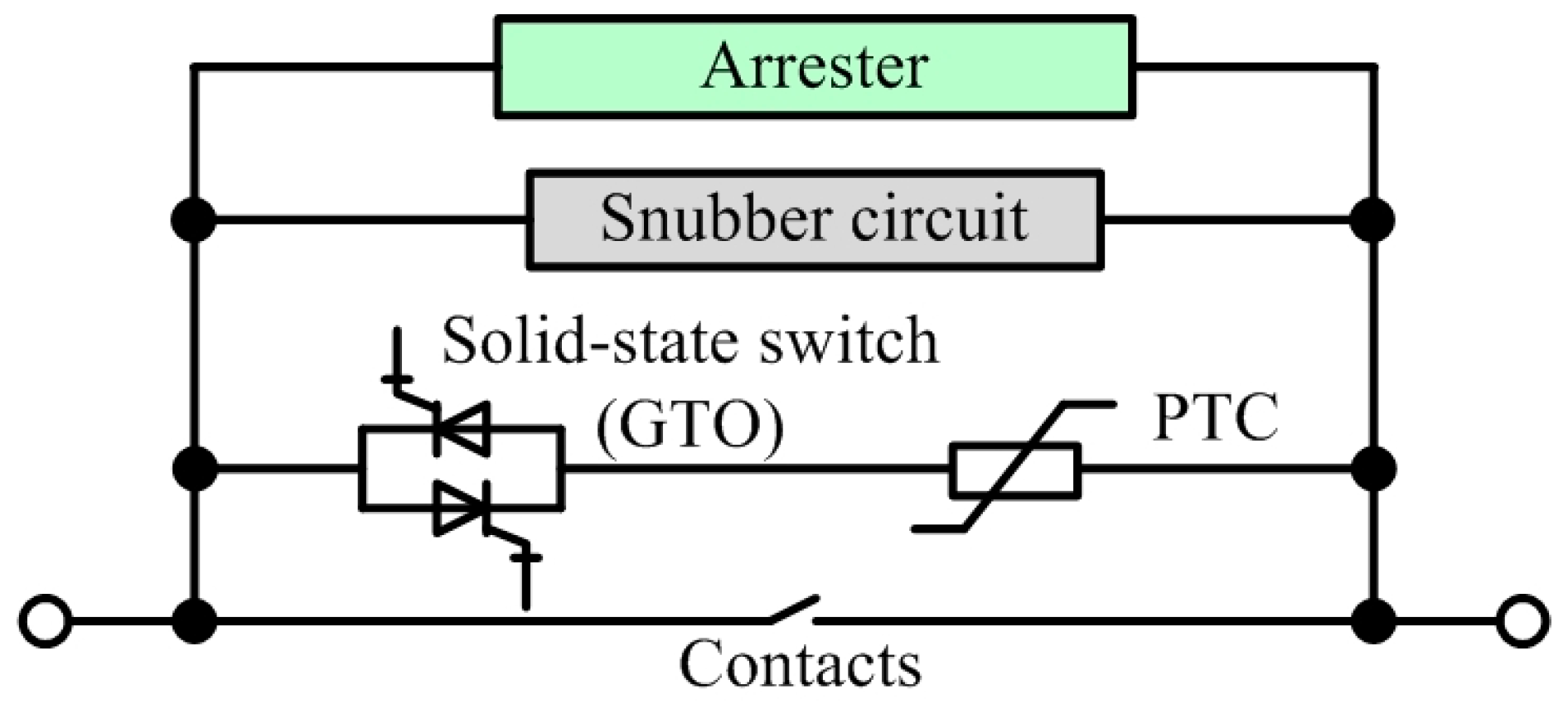
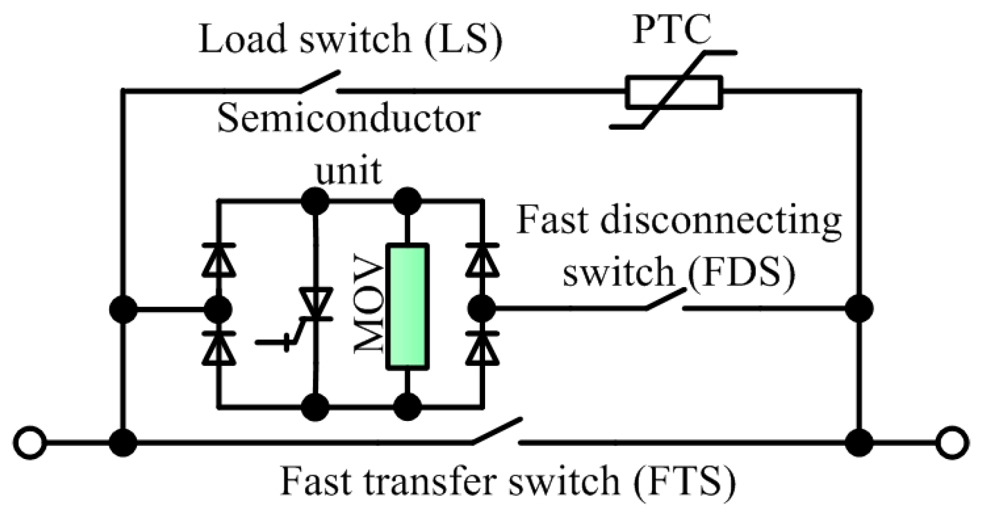
2.3.2. CL-CBs with Positive Temperature Coefficient Thermistors

An HCB with CL ability which is a complex hybrid structure with positive temperature coefficient (PTC) resistor [2], as shown in Figure 5, was proposed in 1996. This CL-CB is put forward based on Figure 1. With the PTC resistor, a huge fault current could be reduced automatically when the mechanical switch is turned off. After the fault switch decreases to a reasonable value, the GTO will turn off to commutate the remaining current into the arrester to clear the fault. The time constant of a PTC resistor is high, which reduces the applications of this configuration in high-speed-response situations.
Figure 5. HCB with PTC resistor in 1996.
As shown in Figure 6, an CL HCB with PTC resistor was proposed in 2003 [21]. The CB consists of a fast transfer switch (FTS), a fast disconnecting switch (FDS), a bi-directional semiconductor switch (e.g., with four diodes and a GTO), a PTC resistor and a load switch (LS). The FTS turns off at a fault to force the current into a semiconductor branch. Then GTO will turn off to let the PTC resistor absorb the energy. Finally, the lowered current will be broken by the LS, which also contributes to insulation of the CB system.
Figure 6. Hybrid CL-CB with PTC in 2003.

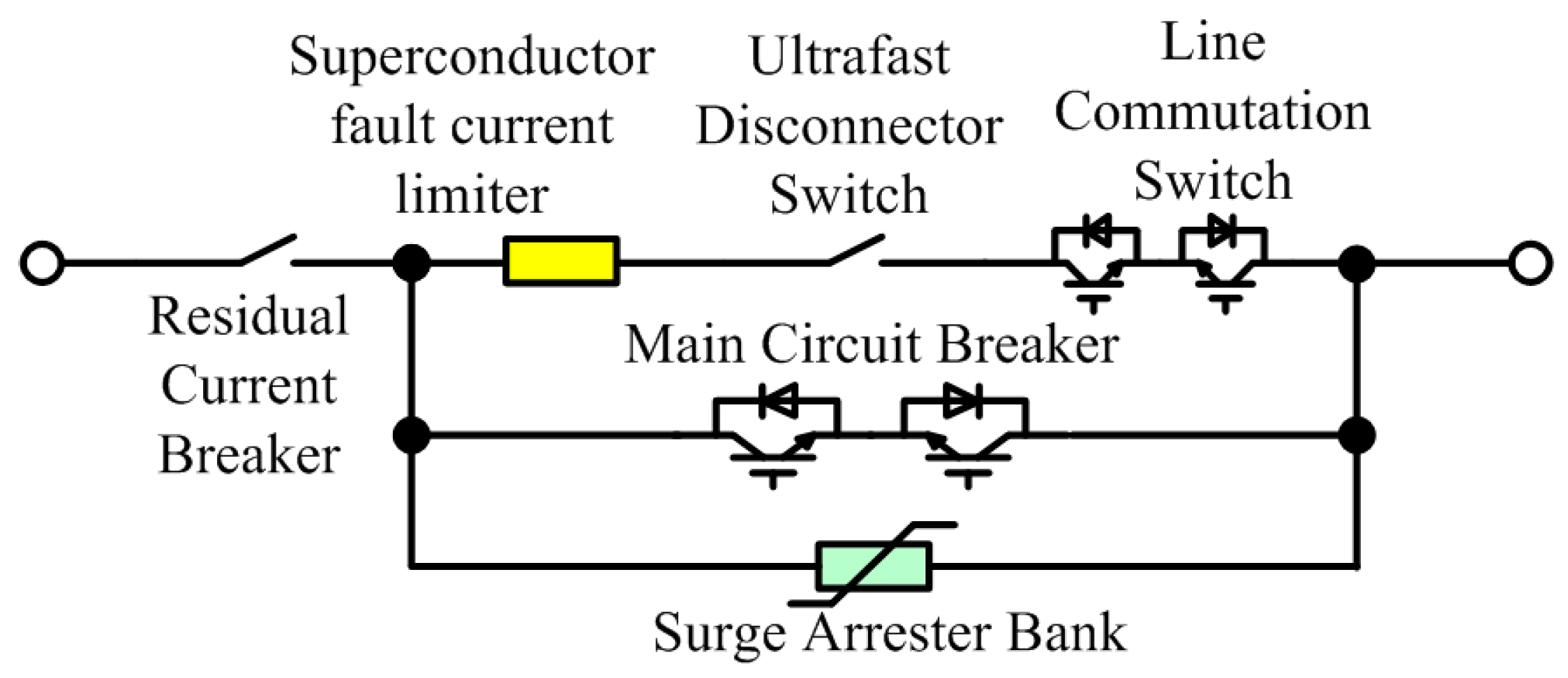
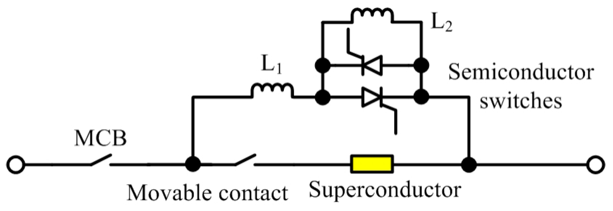
2.3.3. CL-CBs with Superconductors

High temperature superconductors could be used as CL devices. In 1995, a current limiter was proposed on this basis [8]. With negligible resistance below under a critical temperature, and relatively high resistance above the critical temperature, the current limiting could be achieved automatically and smoothly. Superconductors may be used for power distribution systems which are not sensitive to cost and dimensions [22,23,24].
As shown in Figure 7, a superconductor-based HCB for HVDC was proposed in [25] with residual current breaker for insulation, superconductor fault current limiter (SFCL) for automatic current limiting, an ultrafast disconnector switch as main mechanical switch, a line commutation switch (LCS) to guide the fault current into the main semiconductor switch, and a surge arrester bank to absorb the energy stored on the line inductor.
Figure 7. Superconducting HVDC HCB in 2015.
On the other hand, superconductors could be treated as an automatic commutation switch to transfer the current from a mechanical switch to a main semiconductor switch [26]. Some experts have investigated superconductors as inductive components, and used them in CL applications [27,28].

2.4. CL-CBs with Other Switched Components

Apart from resistive components, other passive components, e.g., inductors and capacitors, could also be used together with semiconductor devices for current limiting. As a series-connected component, inductors are used widely for CL purposes, but the voltage overshoot caused by inductive currents must be taken into account to ensure the safety of the semiconductor devices. On the contrary, there is no overvoltage problem for capacitors as CL components, but the current cannot be limited properly because the limitation process is indirect. Another option is forming a combination of capacitor and inductor as a resonant circuit. The impedance of this kind of circuit could change from negligible to a high value by adding semiconductor switches, which is considered more suitable as a CL component than a pure inductor or capacitor.

2.4.1. CL-CBs with Inductive Components

To limit fault currents, a series-connected inductor is more effective [29] than a paralleled capacitor. If an inductor is added without assistance of semiconductor switches, the impedance of the inductor may cause considerable phase shifts and voltage drops, which results in bad voltage regulation and higher system losses.
A CL device with a superconductor and two inductors was proposed in 2008, where the superconductor only works as an automatic switch, and inductors work as current limiters [26]. As shown in Figure 8, the inductance of element L2 is higher than that of L1. When a fault occurs, the resistance of the superconductor increases significantly, and the fault current commutates to the two inductors. The semiconductor switches then trip to allow L2 to eliminate the fault current. This configuration is complicated because of its passive and superconductive components.
Figure 8. A superconductor CL-CB with two inductors in 2008.
A bridge-structured solid-state CL device based on a single inductor working in different mode is shown in Figure 9 [30]. In normal operation, thyristors T1, T2 off and T3, T4 on, the configuration is then a DC inductor with negligible effect on AC power quality. When a fault occurs, T1, T2 on and T3, T4 off, the inductor changes from DC mode to AC mode, therefore the fault current could be reduced.
Figure 9. Solid state CL-CB with an AC inductor and a DC inductor in 2015.

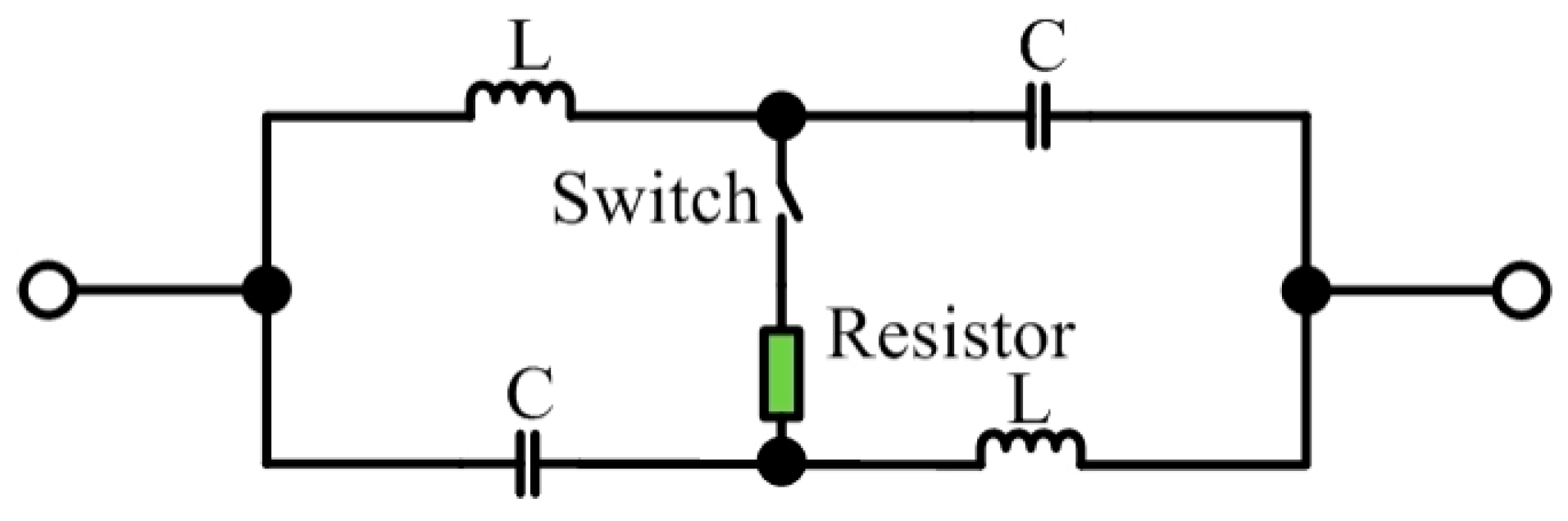
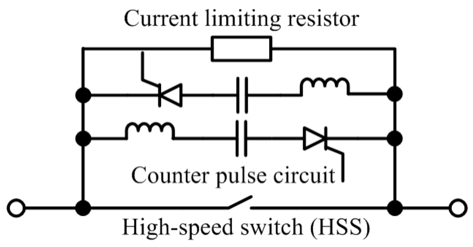
2.4.2. CL-CBs with Inductor-Capacitor (L-C) Components

In 1980, EPRI had also proposed a tuned-impedance CL devices, as shown in Figure 10. Without fault, the mechanical switch is in open state, which cause almost zero impedance on a series L-C resonant circuit. When a short-circuit fault happens, the switch turns on after fault detection, then adds an additional impedance to the circuit to eliminate the fault current. The equivalent impedance in the parallel mode is resistive, therefore no undesired phase shift is added [17].
Figure 10. EPRI tuned-impedance CL devices in 1980.
In 1998, a hybrid current-limiting interrupting device (HCLID) was proposed by experts at the Technical University of Gdansk, Gdansk, Poland. The structure of the HCLID is simple: a mechanical contact, two diode and two thyristors, together with an L-C series-connected circuit [31,32]. As seen in Figure 11, the HCLID may inject a countercurrent into the main path to provide zero-crossing conditions. The mechanical switch could open in reduced current status with fast speed and small arcing. The pre-charged capacitor and inductor increase the dimensions and cost as well as complexity, which is suitable for low-voltage low-power applications.
Figure 11. Hybrid CL interrupting device (HCLID) in 1998.
L-C current limiting components have been mentioned in [33] in 2002. In Figure 12, a more complex approach have been investigated to ensure CL performance and normal operating [34]. Current goes through mechanical switch, inductor of transformer and C2. Negligible impedance formed by a resonant circuit. When a fault occurs, the mechanical switch is tripping with a very small arc. The current commutate from main path to the series-connection of S1 and C1, where S1 is a bi-directional controllable semiconductor switch e.g., thyristor, GTO, insulated-gate bipolar transistor (IGBT) and integrated gate-commutated thyristor (IGCT). By using C1 and S2, the remaining circuit results in a very high impedance with significant current limitation properties. The current-limiting capability is strengthened by closing S2 to add more resistance and inductance. A power dissipative element is used to absorb the remaining circuit energy when the circuit breaker is turned off to interrupt the current.
Figure 12. Hybrid CL-CB with complex tuned L-C elements in 2012.
A solid-state fault current limiting (SSFCL) CB is put forward in Figure 13, using an L-C tank for voltage network applications [35]. Two diodes and five thyristors are needed to form a rectifier. When a fault occurs, this circuit changes into a rectifier bridge and rectifies the AC voltage.
Figure 13. SSFCL CB using resonant L-C tank in 2015.

2.5. Controllable Semicondcutor Devices for Current-Limiting

2.5.1. CL-CB with Semiconductor Power Switches

As shown in Figure 14 [36], an SSCB could work as a CL device. This ‘fault-current limiting and interruption device (FCLID)’ has a bi-directional semiconductor switch, e.g., IGBT or power metal-oxide-semiconductor field-effect transistor (MOSFET), resistor-capacitor (RC) snubber circuit, and a voltage varistor (i.e., a nonlinear resistor). The semiconductor switches could be controlled with pulse-width modulation (PWM) or a linear-region gate signal to limit the current.
Figure 14. Solid-state circuit breaker in 2006.
When with a short-circuit condition, the current is limited to a value higher than the nominal current, therefore the power loss will higher than the nominal power input of the system. This configuration could not work in CL mode on a long-term basis, and as the power must be absorbed by metal oxide varistor (MOV) afterwise, MOV components with large dimensions are needed.
Figure 15 shows a HCB with multi-function [37]. This configuration consists of a fast mechanical switch, a diode bridge, a controllable semiconductor device (GTO or IGBT) and protection components. If a fault is noticed by the current sensor, the fast mechanical switch will switch off immediately. The fault current commutates into the diode bridge. On and off status of the semiconductor part is determined by the only controllable semiconductor switch. Either a PWM signal or linear gate voltage signal could be applied. A resistor-capacitor-diode (RCD) snubber circuit works together with MOV for semiconductor device transit protection.
Figure 15. Multifunction HCB in 2008.
Figure 16 shows a typical CL-CB configuration, with which the current could be eliminated by fast switching of mechanical switch and semiconductor switches [38].
Figure 16. Hybrid CL-CB in 2012.
As shown in Figure 17, ASEA Brown Boveri (known as ABB) in Zurich, Switzerland, have proposed hybrid CB for HVDC systems without arcing and without more induction loss [39]. The commutation switch is a semiconductor with very low breakdown voltage, so that the on-state voltage and on-state loss are extremely low. When a fault occurs, the commutation switch will open, and the current commutates to main semiconductor branch. After the branch current becomes zero, the mechanical disconnector switch opens rapidly without arcing, and keeps a long insulation distance. Then main semiconductor switch opens to send all electronic energy to surge arrester bank. The main semiconductor switch as well as the surge arrester bank are series-connected for high voltages, as described at the beginning of this section.
Figure 17. ABB hybrid HVDC circuit breaker in 2011.

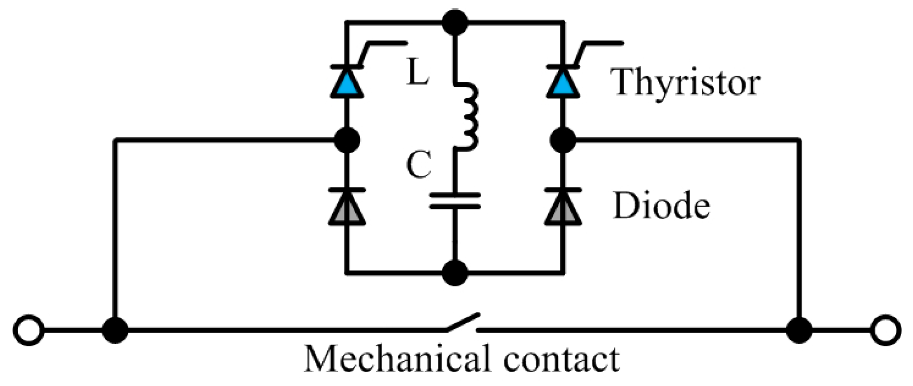
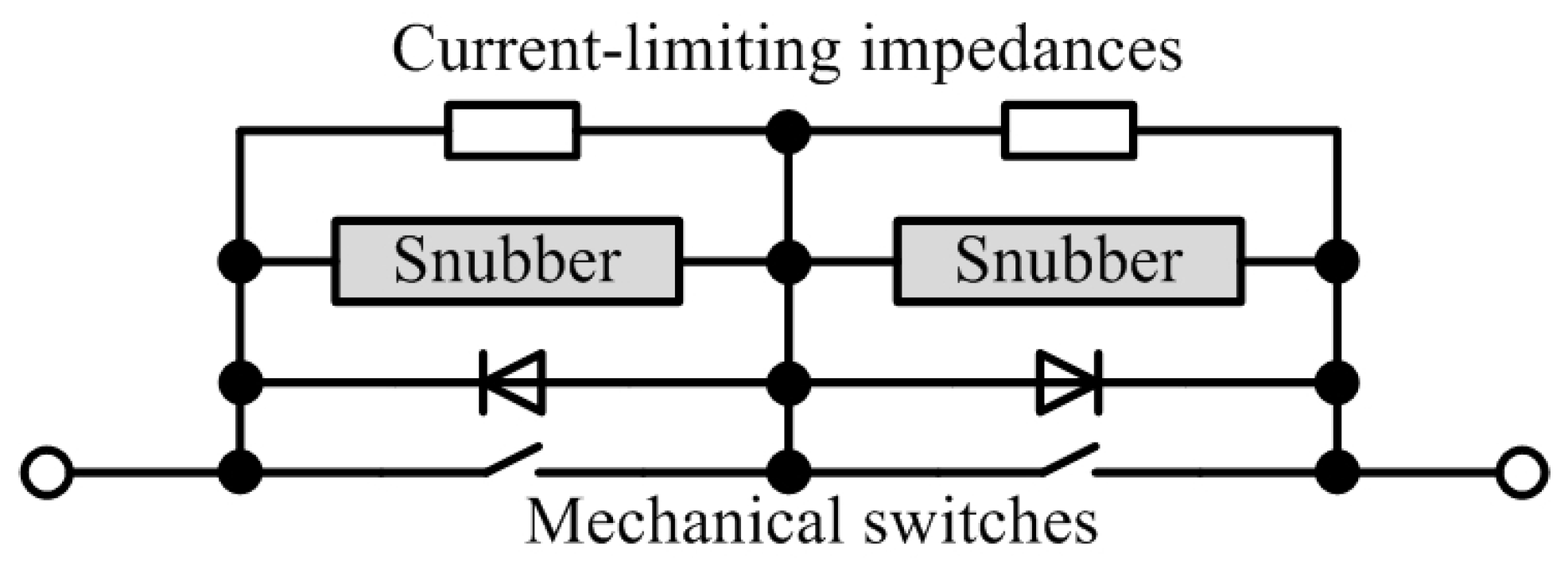
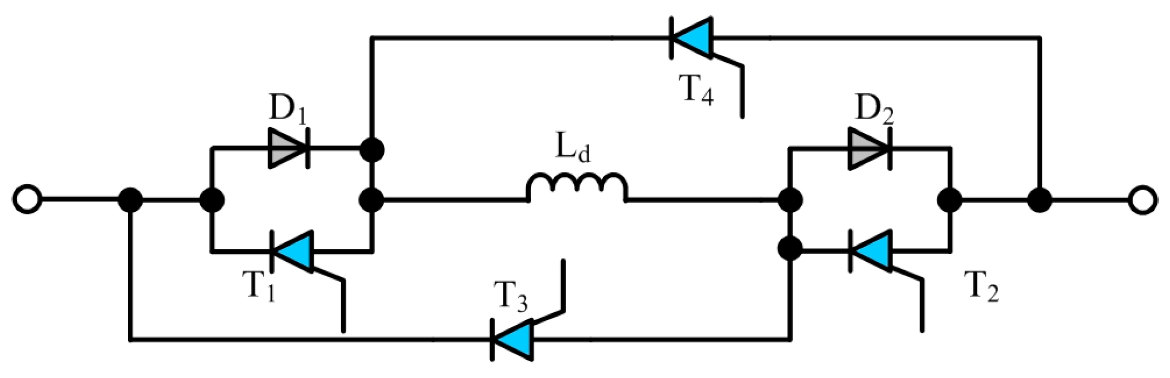
2.5.2. Active Bridge Configurations of CL-CBs

Reference [40] introduced a CL-CB for AC grids with a three-phase thyristor bridge. As shown in Figure 18a, by using a three-phase series-connected isolating transformer, three-phase thyristor bridge and a DC inductor, this CL-CB could not influence the grid voltage in ordinary working mode, but when a short-circuit fault happens, the DC side inductance will be added into the circuit loop automatically, therefore achieving no delay for the fault current limitation.
Figure 18. Inductor-bridge type solid state current limiters: (a) Three-phase series thyristor bridges with isolating transformers (4-arms); (b) Single-phase thyristor bridges with DC inductor; (c) Half-controlled IGCT bridges with AC and DC inductors.
As shown in Figure 18b, if the transformer is taken off from the first figure, single-phase H-bridge configuration could also be used for CL purposes. Another AC-side inductor is added up to this circuit working together with DC inductor. With the AC inductor, the current rating of the circuit could be increased, however, an MOV must be connected across the AC inductor to protect the semiconductor devices from over-voltage damage [41].
As shown in Figure 18c, let’s go one step further, replacing two thyristor with diodes, and two thyristors with IGCT switches, then this third configuration could obtain a similar performance. Only two controllable semiconductor devices are needed [42].
Static synchronous series compensators (SSSC), as a series-connected semiconductor converter module, were investigated by a few experts for CL purposes [43,44,45,46]. As shown in Figure 19, SSSC has the same H-bridge structure as a static synchronous compensator (STATCOM), but uses series-connection rather than paralleled connection [47]. The SSSC can provide controllable compensating voltage and capacitive or inductive power, which could improve the quality of electric energy [48]. SSSC may be a good multi-functional flexible fault current limitation component solution.
Figure 19. SSSC bridge current limiters in 2000 and 2012: (a) Single-phase cascaded H-bridge with separating capacitors; (b) Three-phase bridges with common DC capacitor and isolating transformer.

2.6. Summary

A brief summary is put forward in Table 1 to show the circuit breakers in different categories, and discuss their advantages and disadvantages. Some observations are warranted:
Table 1. Summary of CL-CBs (mechanical or semiconductor) [49].
(a)
Mechanical switches, as one half of the HCB configuration, need more investigation about lifting the tripping speed;
(b)
HCBs with auxiliary semiconductor switches will be widely used for HVDC systems because of their natural superiority: no-arcing, acceptable switching speed, and low transmission power loss;
(c)
Superconductor-based circuit breakers are quite expensive and have huge size/weight, so they may be only used in HVDC systems because of their insensitivity of floor space. Further investigation could be on implementation and higher-temperature superconductors;
(d)
As current-limiting is becoming more intelligent, semiconductor devices will be widely applied, but their reliability must be taken into account;
(e)
Resistive CL-CB has really high power dissipation, it might be only used for short-term limiting;
(f)
Inductive CL-CB and L-C based CL-CB are sensitive to frequency changes, so the robustness is not perfect. The dynamic response must be analyzed before any conduction;
(g)
Bridge-connected CL-CB has the best flexibility and controllability, but may suffer from higher power loss and the need for other additional components. Active CL-CB with SSSC may be a good solution for DC/AC systems for its controllable reactive power generation capability and its multi-function of short-circuit protection;
(h)
Wide-band-gap (WBG) devices e.g., SiC MOSFET are recommended for fast breaking as well as current limiting, but the overall cost should be taken into consideration.

3. Novel Circuit Breaker Concepts with Different Power Devices

This part discusses basic HCB/SSCB configurations with different control methods as well as semiconductor devices. Novel configurations are proposed afterwards based on the basic topologies with some good features. The applications of different power devices in these circuit breakers are analyzed with further discussion.

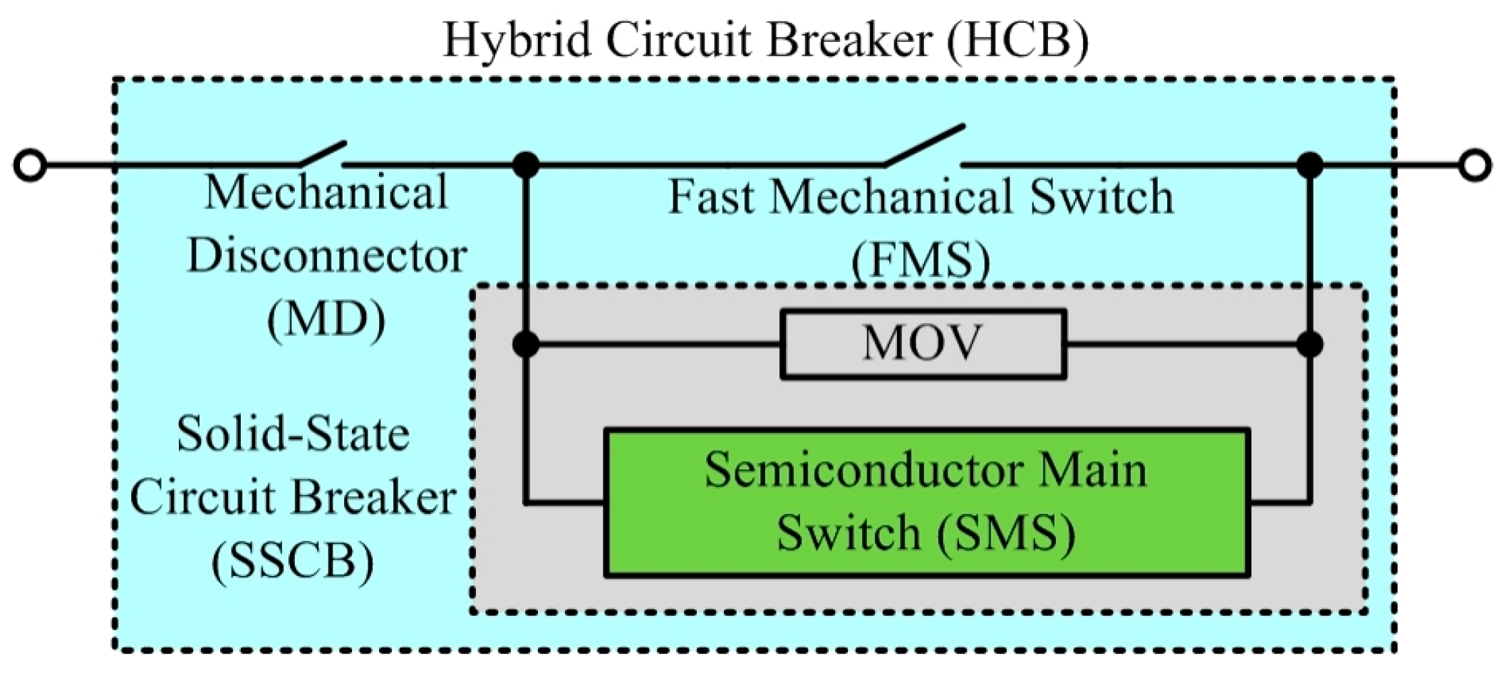
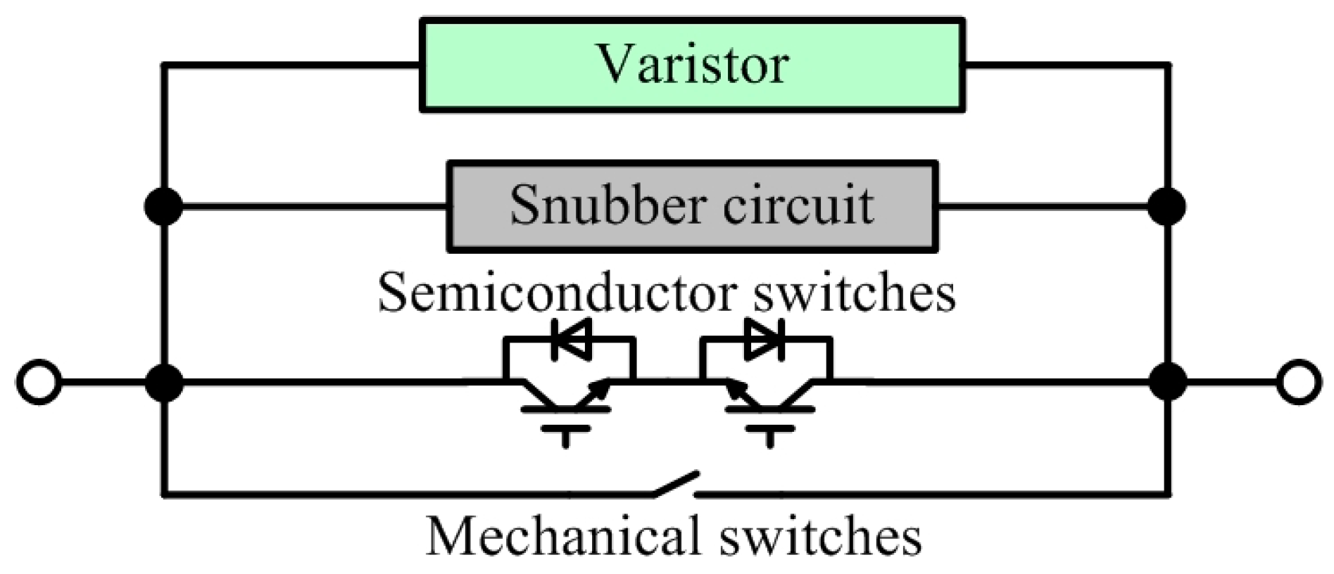
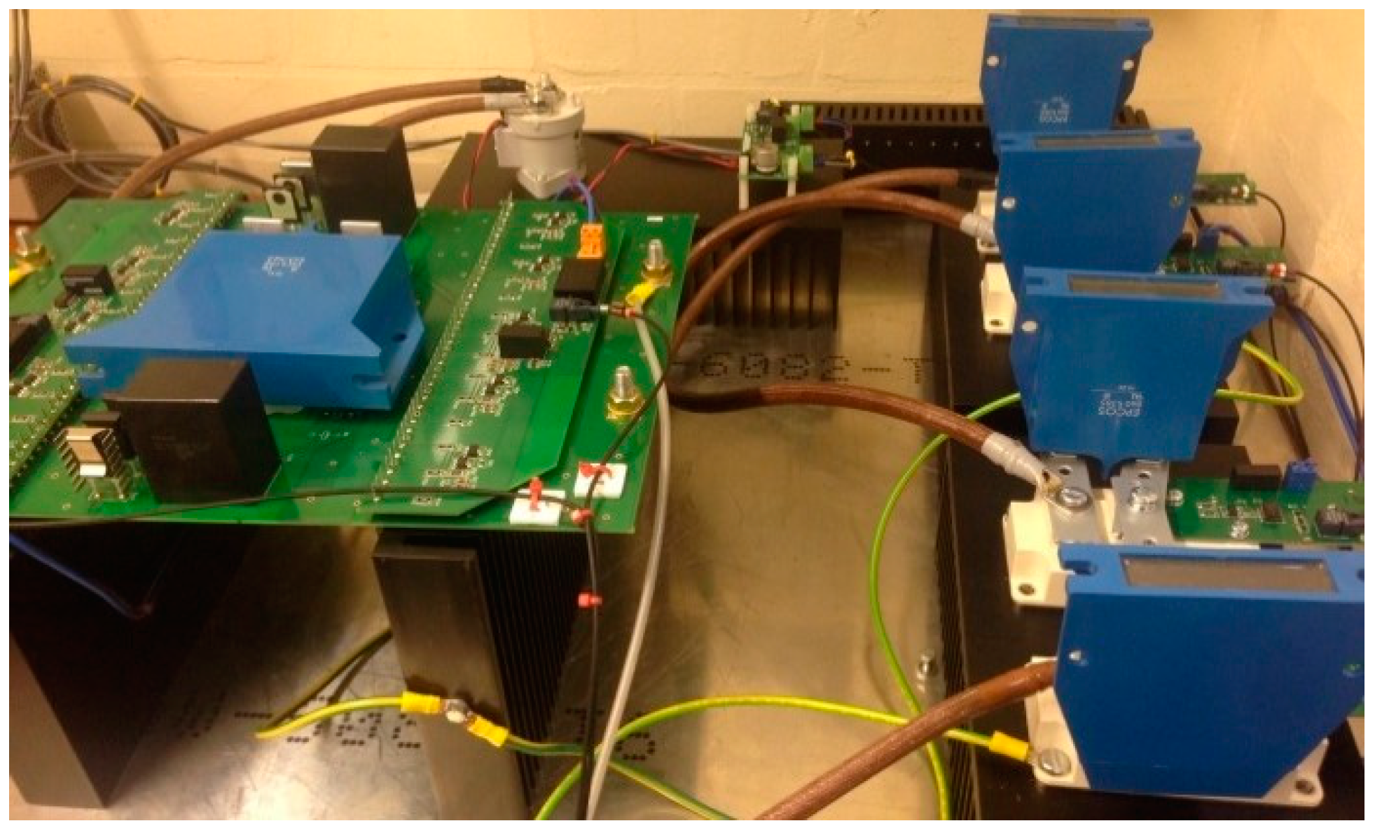
3.1. Basic HCB/SSCB Configuration in Low-Voltage AC/DC Grids

Figure 20 shows the basic configuration of HCB/SSCB. SSCB consists of a semiconductor main switch (SMS) and a metal oxide varisor (MOV). HCB is the combination of SSCB with fast mechanical switch (FMS) and mechanical disconnector (MD). The latter two are optional for different applications. Both PWM control (i.e., a pulsed gate signal) and linear region gate control (variable gate voltage signal for semiconductors) of SMS are appropriate for AC and DC applications, even better with WBG semiconductor devices of higher switching speed and higher junction temperature. A novel phase-shift control method could be used for AC applications, avoiding supplementary impedance (e.g., inductor and resistor) because of natural zero-voltage-crossing ability.
Figure 20. Basic SSCB/HCB configuration diagram.

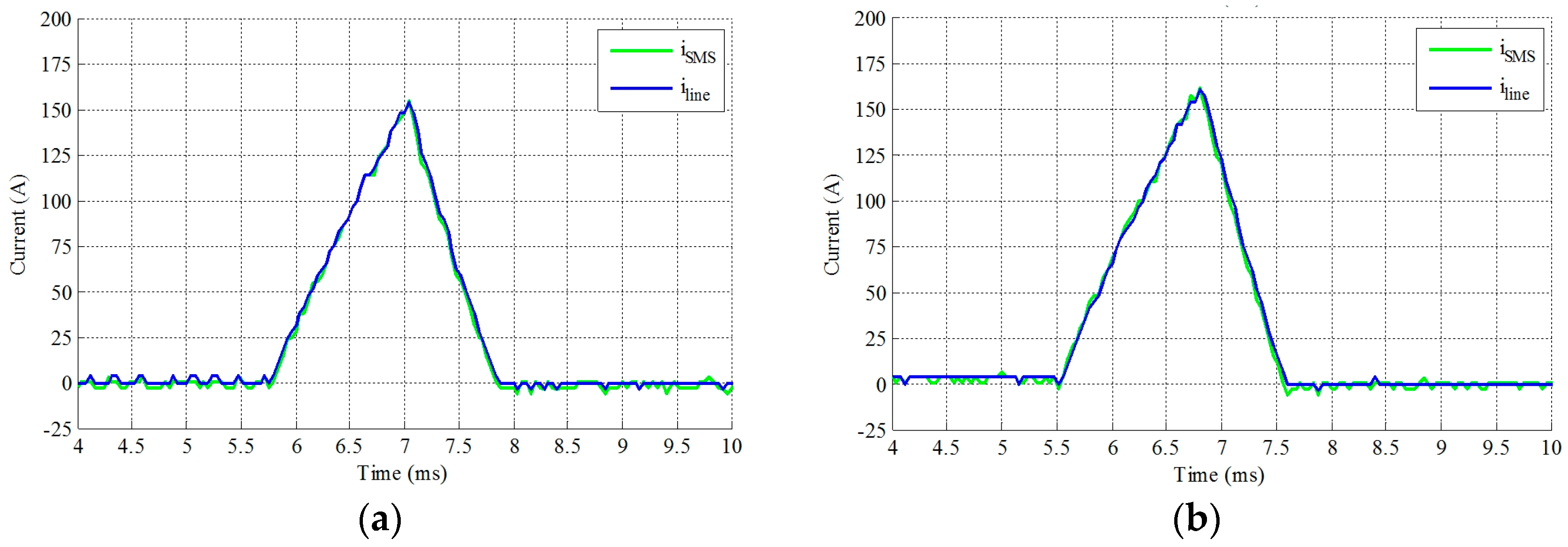
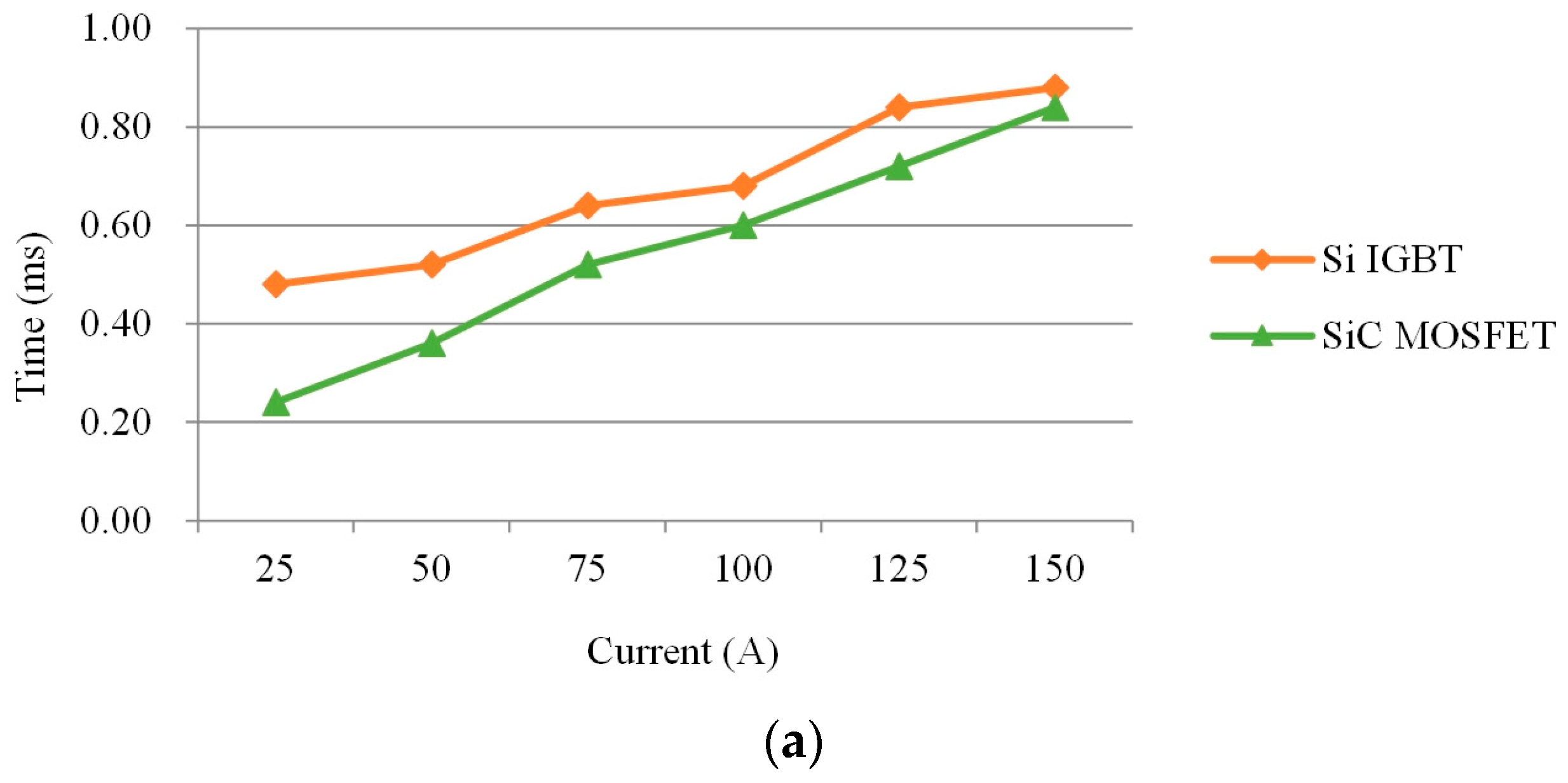
3.1.1. Fast Breaking of SSCB or HCB with WBG Devices
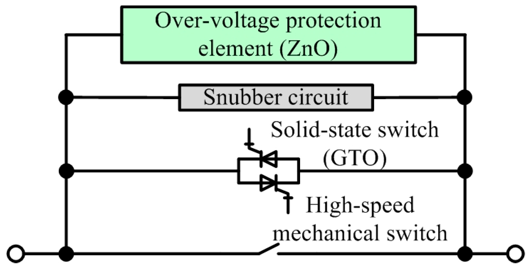
For SSCB with WBG devices, the functions of component could be described as follows:
(a)
FMS carries the main current with low conduction loss;
(b)
SMS is to cut off fault current with a higher speed;
(c)
MOV absorbs the remaining energy of line inductance to avoid over voltage across SMS;
(d)
A mechanical disconnector is needed to ensure electrical insulation while all turned off.
Figure 21 shows the photograph of an HCB/SSCB testing prototype with SiC MOSFETs (15 Cree C2M0025120D in a parallel, common-source configuration to allow bi-directional power flow) or silicon (Si) IGBT (Infineon FZ600R17KE3) as a comparison. A GIGAVAC GX26CCB mechanical switch is chosen as the FMS part of HCB.
Figure 21. Photograph of a HCB/SSCB prototype with SiC power MOSFETs or Si IGBTs.
Figure 22 and Figure 23 show the experimental results of HCB operation (tripping current 150 A for Figure 22) with a SiC MOSFET and Si IGBT. In Figure 22a, it is apparent that the on-state resistance of SiC MOSFET is very small (about 3.33 mΩ), therefore both FMS and SMS are conducting during normal operation. Figure 23 shows that the total clear time (including turn-off time of FMS, turn-off time of SMS and energy absorbing time by MOV) of SiC MOSFET based HCB is lower than for a Si IGBT-based HCB.
Figure 22. Experimental current waveforms of HCB with different semiconductor devices: (a) With SiC MOSFET; (b) With Si IGBT.
Figure 23. Comparison of HCB with Si IGBT and SiC MOSFET: Total clear time.
Figure 24 and Figure 25 show the experimental results of SSCB operation (tripping current 150 A for Figure 24) with SiC MOSFET and Si IGBT. As the peak current of Si IGBT based SSCB is higher than that of SiC MOSFET based SSCB, the switching speed of the latter is still higher. Figure 25a confirms this result. Figure 25b shows the normal operation efficiency comparison of these two SSCBs. It is observed that the power loss of the SiC MOSFET-based SSCB is lower than that of the Si IGBT-based SSCB when the current is small.
Figure 24. Experimental current waveforms of SSCB with different semiconductor devices: (a) With SiC MOSFET; (b) With Si IGBT.
Figure 25. Comparison of SSCB with Si IGBT and SiC MOSFET: (a) Total clear time; (b) Normal operating efficiency.
Device selection and specification should be grounded in practical application requirements. It is apparent that, with SiC MOSFET, the clearing speed of HCB and SSCB will be higher than that with Si IGBT. The power loss of a SiC MOSFET-based SSCB may be lower than that of a Si IGBT one with appropriate device selections.

3.1.2. Current Limitation Method with PWM Strategy

With current limitation by PWM chopping for semiconductors, SiC MOSFETs get higher marks than Si IGBTs because of their higher junction temperature and lower switching losses. Figure 26 shows a case study (simulation results) of PWM-based current limitation with a discontinuous current. Although the current ripple is large, the downstream devices may be still working for specific loads (e.g., incandescent lamps). The elimination of semiconductor device loss and junction temperature could be obtained by reducing switching frequency.
Figure 26. Case study (simulation results) of PWM CL strategy: Discontinuous current.

3.1.3. Current Limitation by Gate Voltage Control

As the on-state voltage of power MOSFET or IGBT could be controlled by changing the gate voltage signal, the current limitation may be achieved by linear region control. In this condition, power MOSFET or IGBT works as a variable resistor. WBG devices may be also better for this application because of higher allowable power dissipation. But this is now still restricted because of the power module package temperature limit. Figure 27 show a case study of this scheme with Simulation Program with Integrated Circuit Emphasis (SPICE) software. A detailed Cree SiC MOSFET C2M0025120D SPICE model (105 in parallel) is placed in the simulation for variable gate voltage control with different drain to source resistance.
Figure 27. Case study (simulation results) of linear region CL strategy with SiC MOSFET: (a) Line current and junction temperature without current limiting; (b) With current limiting.

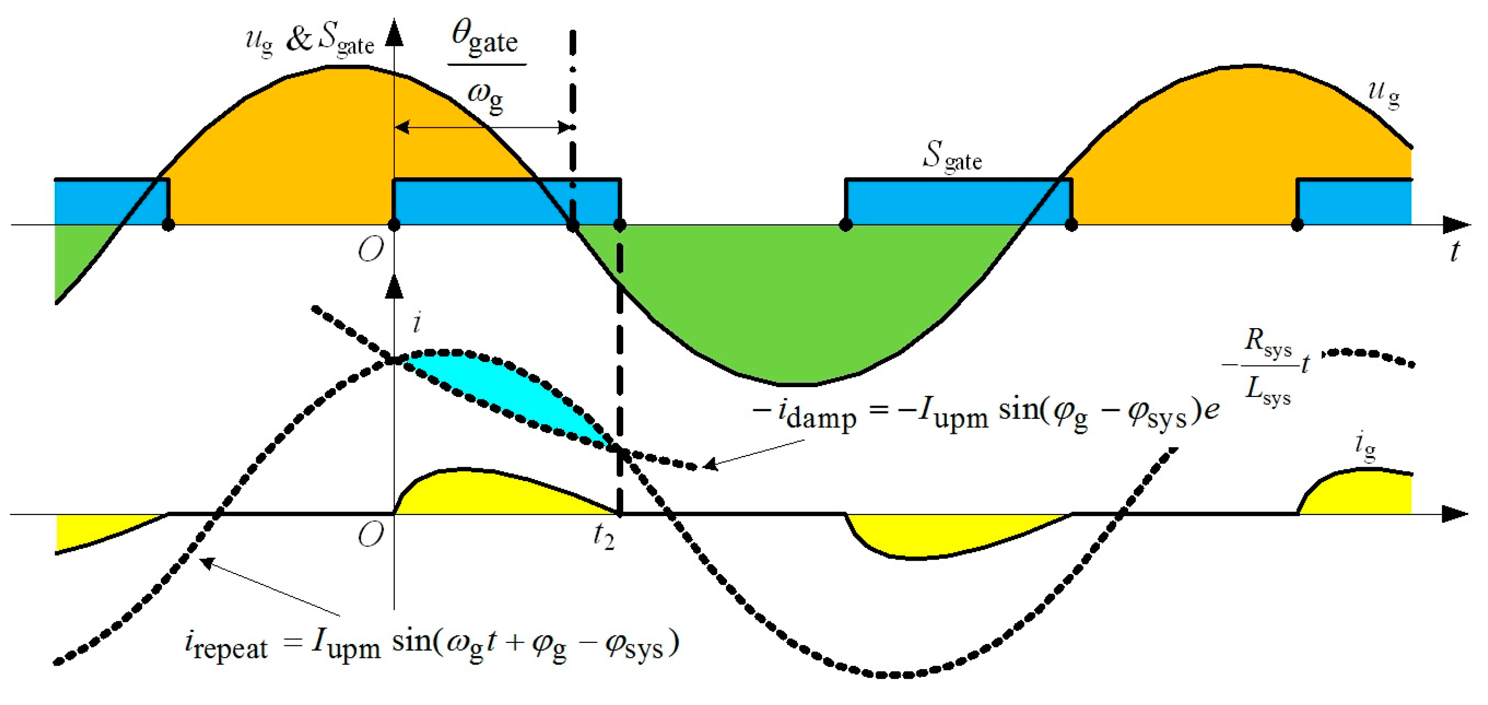
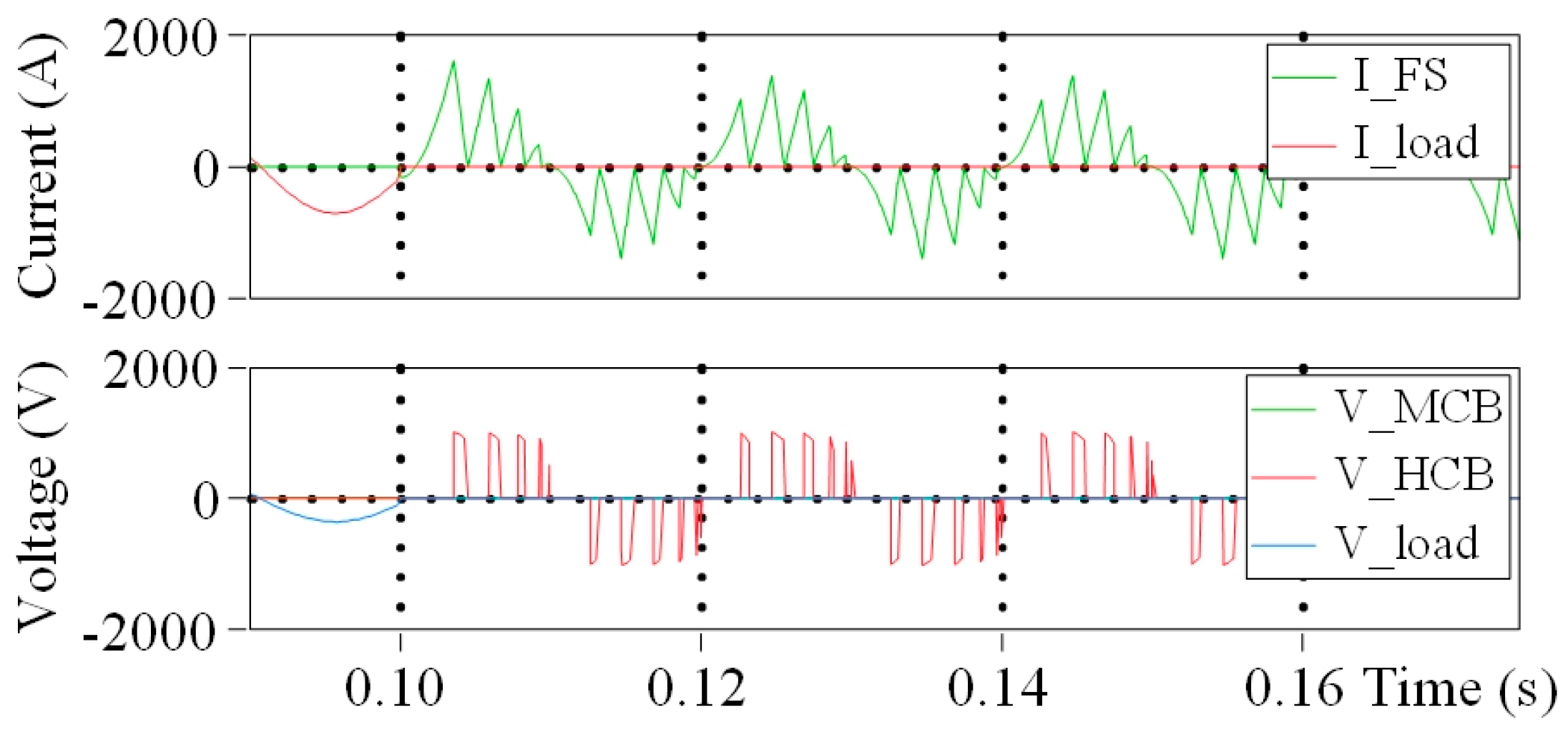
3.1.4. A Novel Current-Limiting Method for Basic HCB in Low-Voltage AC Grids

In this Section, a novel current-limiting control strategy is proposed and applied to basic SSCB circuit breaker configurations without any added passive components (see Figure 20). The current limitation is implemented by phase-shifting of AC voltage and current, therefore obtaining controlled zero crossing of current. As the semiconductor switches is full on or off, there will be no significant power loss on SSCB, which means that there is no extra heat generated, as shown in Figure 28. With the schematic phase-shifting method in Figure 28, the semiconductor is in zero current switching (ZCS) condition, therefore reduce the power loss even more. All fully-controlled semiconductor devices could be applied.
Figure 28. The principle of the phase-shifting current-limiting method.
As shown in Figure 28, two components form the line current: the damping component i damp and the repeating component i repeat . When the fundamental angular frequency ω g is constant (e.g., 50 Hz or 60 Hz), the duty ratio of semiconductor device in one period is D gate , the per-unit (p.u.) peak current I g , peak and p.u. root mean square (RMS) current I g , RMS could be described as the functions of phase angle of the system impedance φ sys and gate phase angle θ gate [ 0 , π φ sys ] , that is: D gate = ω g t 2 π = f D gate ( θ gate , φ sys ) , I g , peak , pu = I g , peak I upm = f I peak , pu ( θ gate , φ sys ) and I g , RMS , pu = I g , RMS I upm = f I RMS , pu ( θ gate , φ sys ) .
Figure 29a shows the detailed control diagram upon this strategy. And a basic simulation result is shown in Figure 29b. It is definite that peak current or RMS current could be controlled very well with peak current reference signal. With the benefits of low cost, control robustness with linear load, good control accuracy, low size, low weight, and finally lower heat dissipation, this control method could be used in many areas. However, in the application fields which requires good AC current waveform performance, simpler control or only DC operation, this method is not applicable.
Figure 29. Phase-shifting current-limiting method: (a) General control diagram of current limitation; (b) Type Z ( I upm = 3 I n ) simulation waveforms: instant/peak reference/RMS currents and gate signals.

3.1.5. Limitation of Basic SSCB/HCB Configurations

Although basic SSCB and HCB are simple in structure, and can be working in a series of mode (fast switching, current limiting by PWM, current limiting by gate voltage control, current limiting by phase shifting), there are a few limitations:
(a)
The switching speed of a basic HCB depends on the tripping performance of FMS, which limits the switching speed of HCBs to several milliseconds;
(b)
The power loss of basic SSCBs is high and not acceptable in many cases, therefore they are not suitable in many applications;
(c)
Current limiting by PWM introduces high power losses on MOV components and current limiting by gate voltage control introduces high power loss on semiconductor power devices, therefore the application area is limited;
(d)
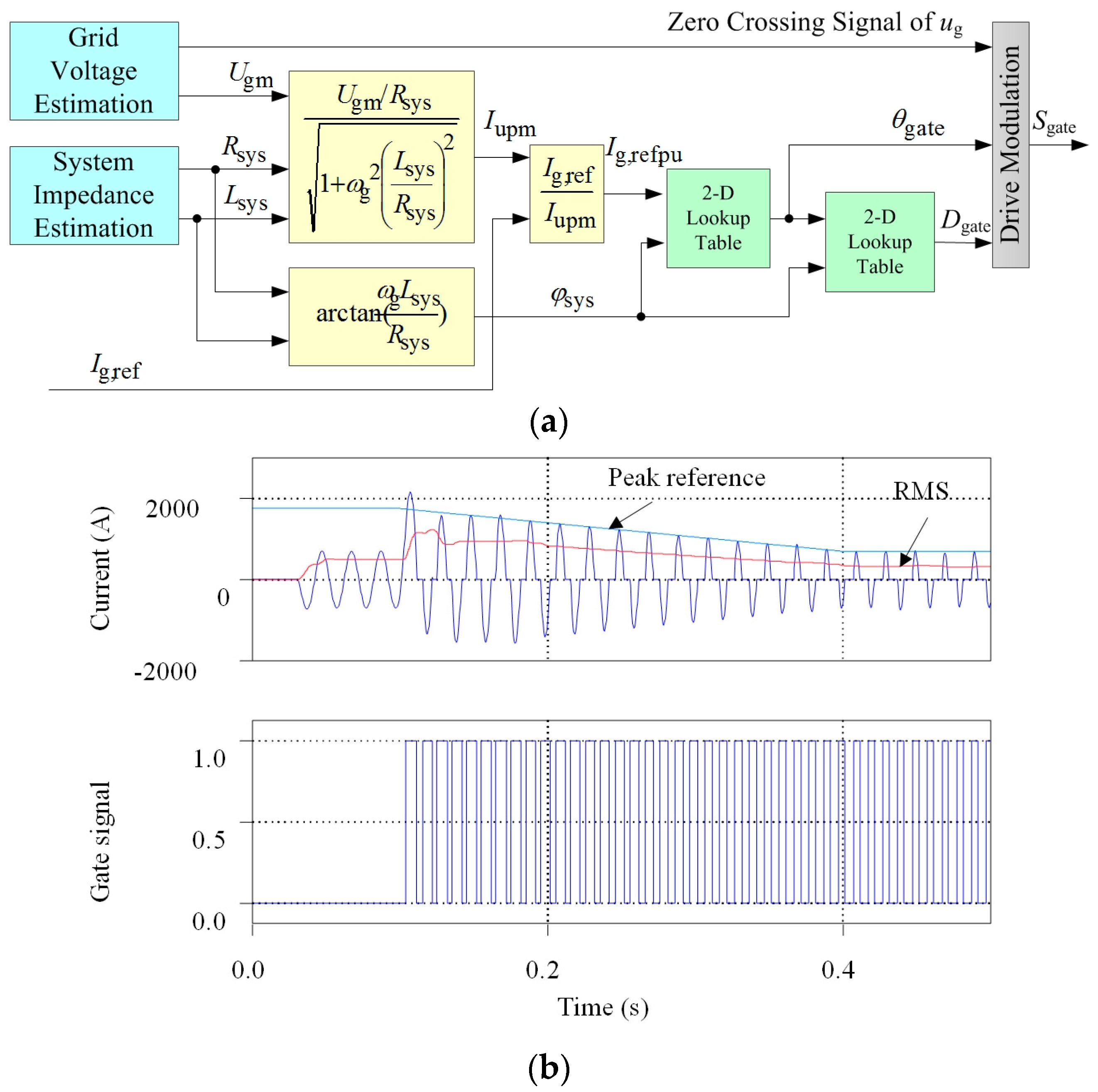
Current limiting by phase shifting could only be used in AC systems and with large current harmonics;
(e)
Although SiC devices may confer an advantage to basic SSCB/HCB configurations with fast breaking (higher switching speed), PWM current limiting (higher switching speed and junction temperature), linear gate voltage control current limiting (higher junction temperature), the cost of SiC MOSFETs is still much higher than that of Si IGBTs, which bounds the spread of SiC MOSFETs in circuit breaker applications.

3.2. Novel CB Configurations with Different Semiconductor Devices

Novel circuit breaker configurations based on SSCB/HCB concepts are investigated to improve performance, as mentioned in Section 3.1.5. Three novel HCB/SSCB configurations are proposed in this section: with Configuration 1 (hybrid), the fault current is broken by the FMS itself; With Configuration 2 (hybrid), the fault current is broken by a series-connected semiconductor transfer switch (STS) to ensure there is no arcing for the mechanical part; with Configuration 3 (pure SSCB), the fault current is broken by SMS with the help of STS, which is an ultra-fast solution with acceptable power loss.

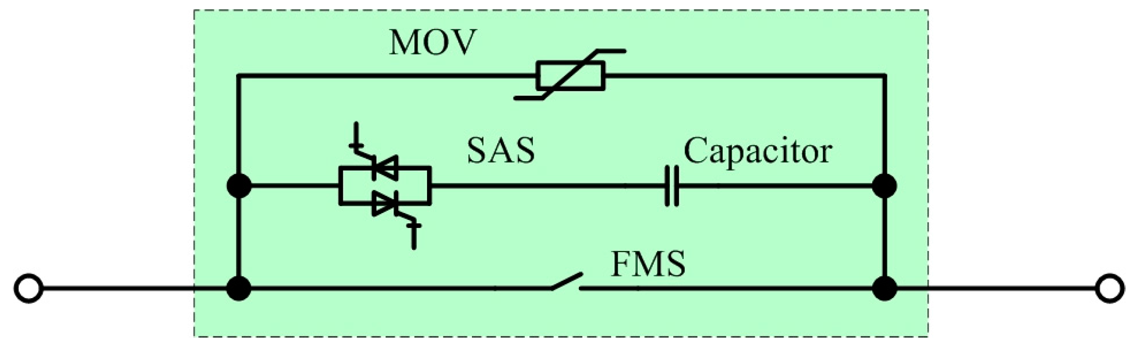
3.2.1. Configuration 1: HCB with Capacitor

Configuration 1 is shown in Figure 30, which consists of an FMS, a semiconductor accessary switch (SAS), a capacitor and an MOV arrester. FMS is used to carry the main normal operation current and break any huge fault current (up to the ultimate short-circuit breaking capacity Icu) as well. SAS is the semiconductor switch which can carry a surge current (i.e., fault current) for a certain amount of time, and should be a thyristor-type device e.g., normal thyristor and GTO. A capacitor is implemented to force the current across zero, therefore a thyristor-based SAS could turn off automatically.
Figure 30. Novel configuration 1: Hybrid solution of FMS + SAS + Capacitor + MOV.

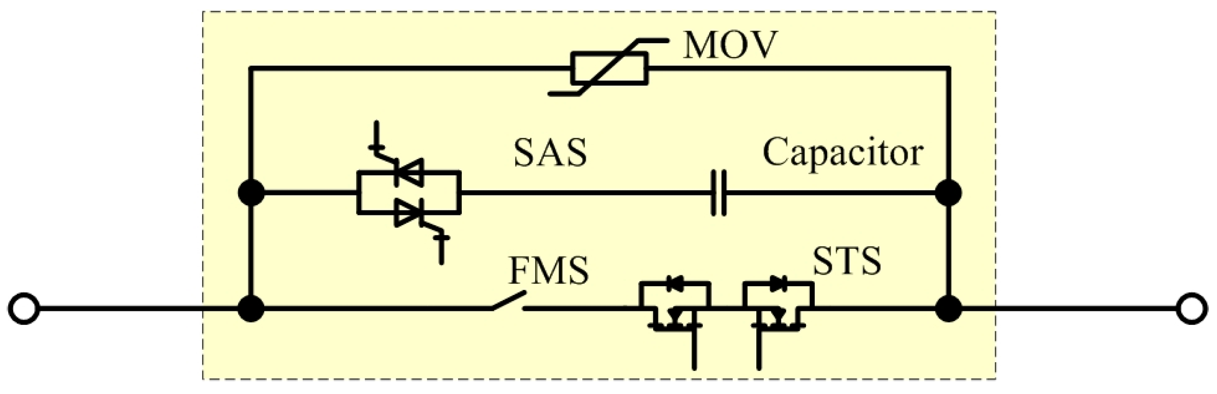
3.2.2. Configuration 2: HCB with STS and Capacitor

Configuration 2, which consists of an STS, an SAS, a capacitor and an MOV arrester, is shown in Figure 31. STS is the series-connected semiconductor switch which can carry the normal operating current and carry/break the fault current (up to Icu). With the voltage rating of only few tens of volts and very small on-state resistance, paralleled connection of Si MOSFETs is a good choice for STS [53].
Figure 31. Novel configuration 2: Hybrid solution of FMS + STS + SAS + Capacitor + MOV.
In normal operation, FMS and STS carry the main current (continuous nominal current and up to 10 times of overload current). The advantage of Configuration 2 is the absence of mechanical switch arcing because the fault current can easily commutate to the SAS branch with STS.

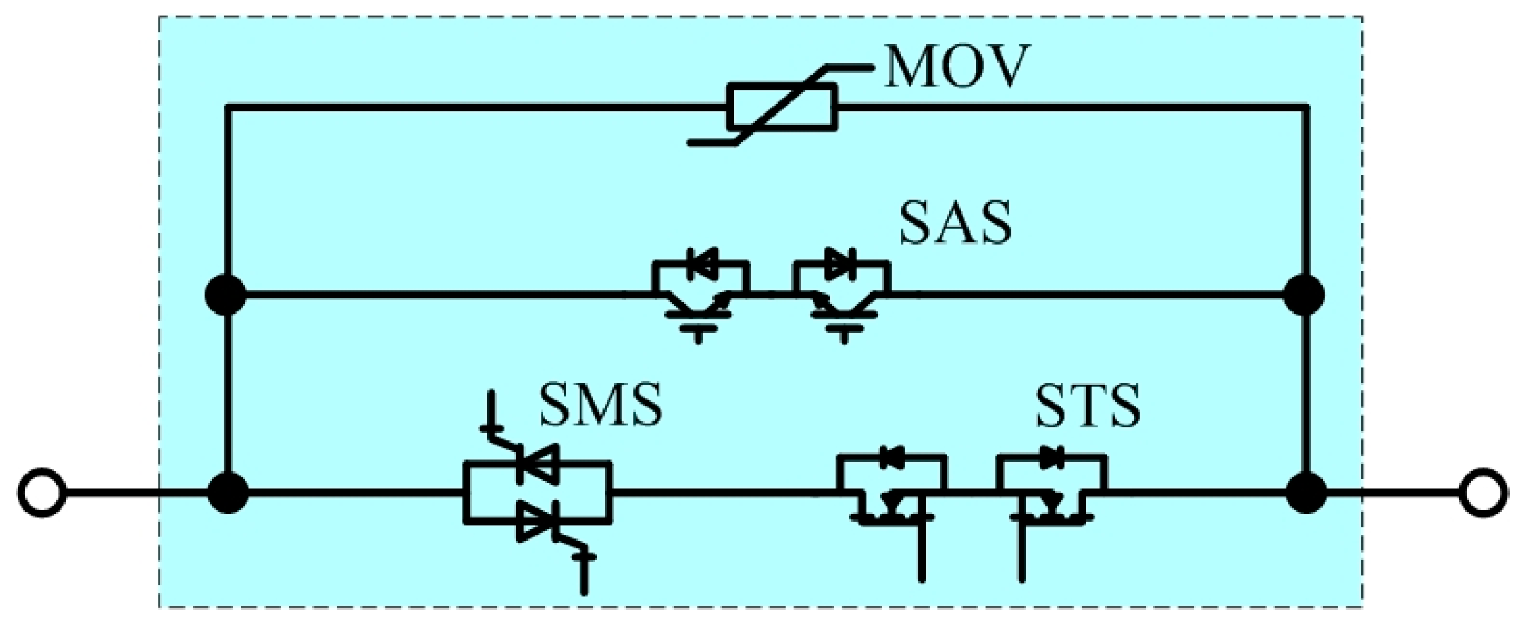
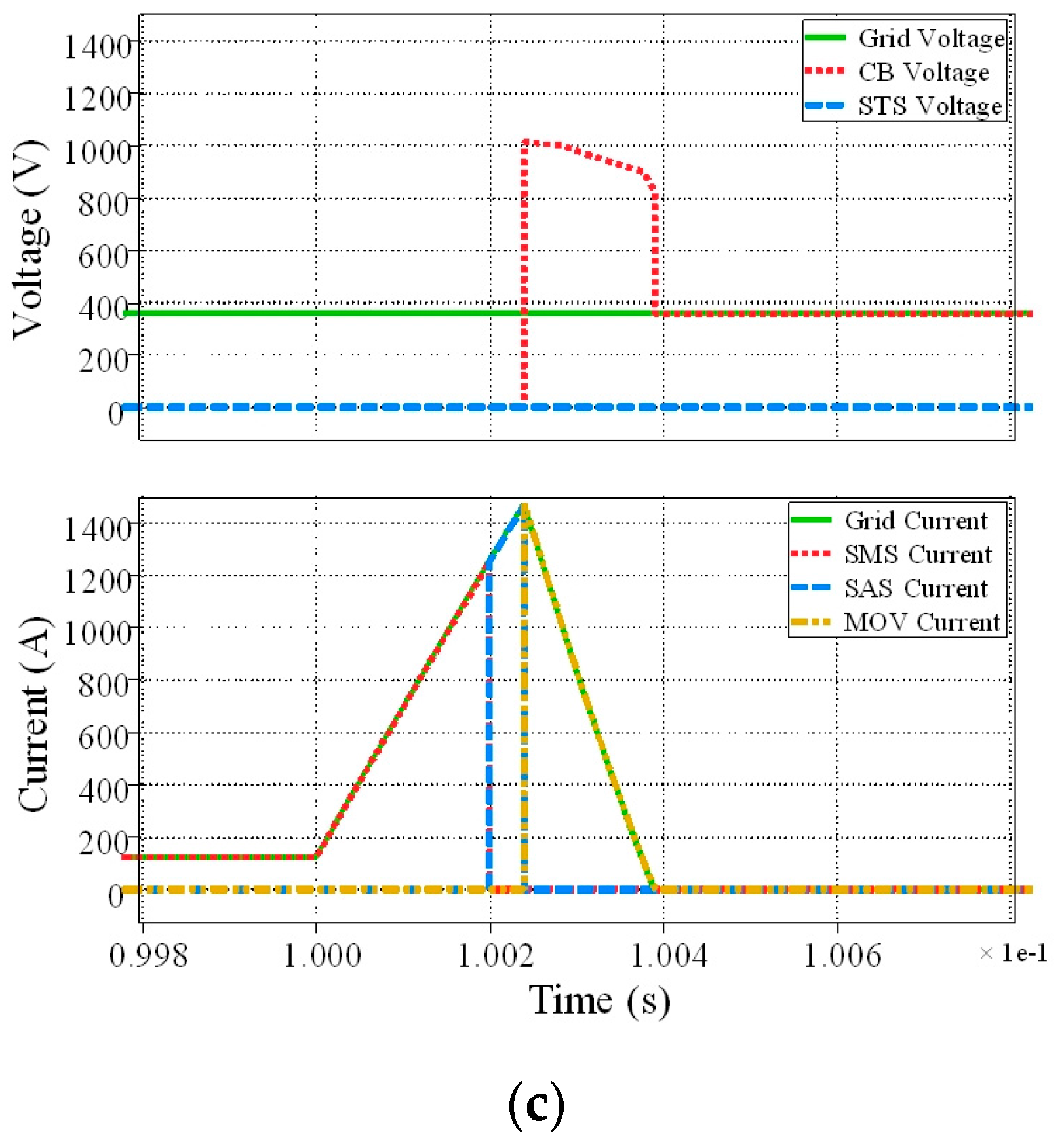
3.2.3. Configuration 3: Pure SSCB with Thyristor and STS (A Better Solution)

Configuration 3 (pure SSCB), which consists of an SMS, an STS, an SAS and an MOV arrester is shown in Figure 32. The SMS is to carry the main normal operation and fault current. To get a lower on-state power loss, SMS could be symmetrical thyristors. STS is the series-connected semiconductor switch which can carry the normal operating current and carry/break the fault current as well. SAS is the semiconductor switch which carries a surge current (i.e., fault current) for a certain amount of time and then breaks it, which could be a IGBT or a GTO (in consideration of cost). MOV arrester is to absorb the remaining energy of line inductance, and protect SMS from over-voltage.
Figure 32. Novel configuration 3: Solid-state solution of SMS + STS + SAS + MOV.
In normal operation, a SMS (thyristor) carries the main current (continuous rated current and up to 10 times of overload current). When a short-circuit condition occurs, the fault could be detected. Then a trip signal is sent first to STS. With a very short delay (in microseconds), the STS trips and commutates the fault current to MOV branch rapidly with zero voltage. After the current of SMS branch definitely goes to zero, SMS turns off automatically. Then the remaining energy of line inductance is absorbed by MOV to reduce the line current to zero.

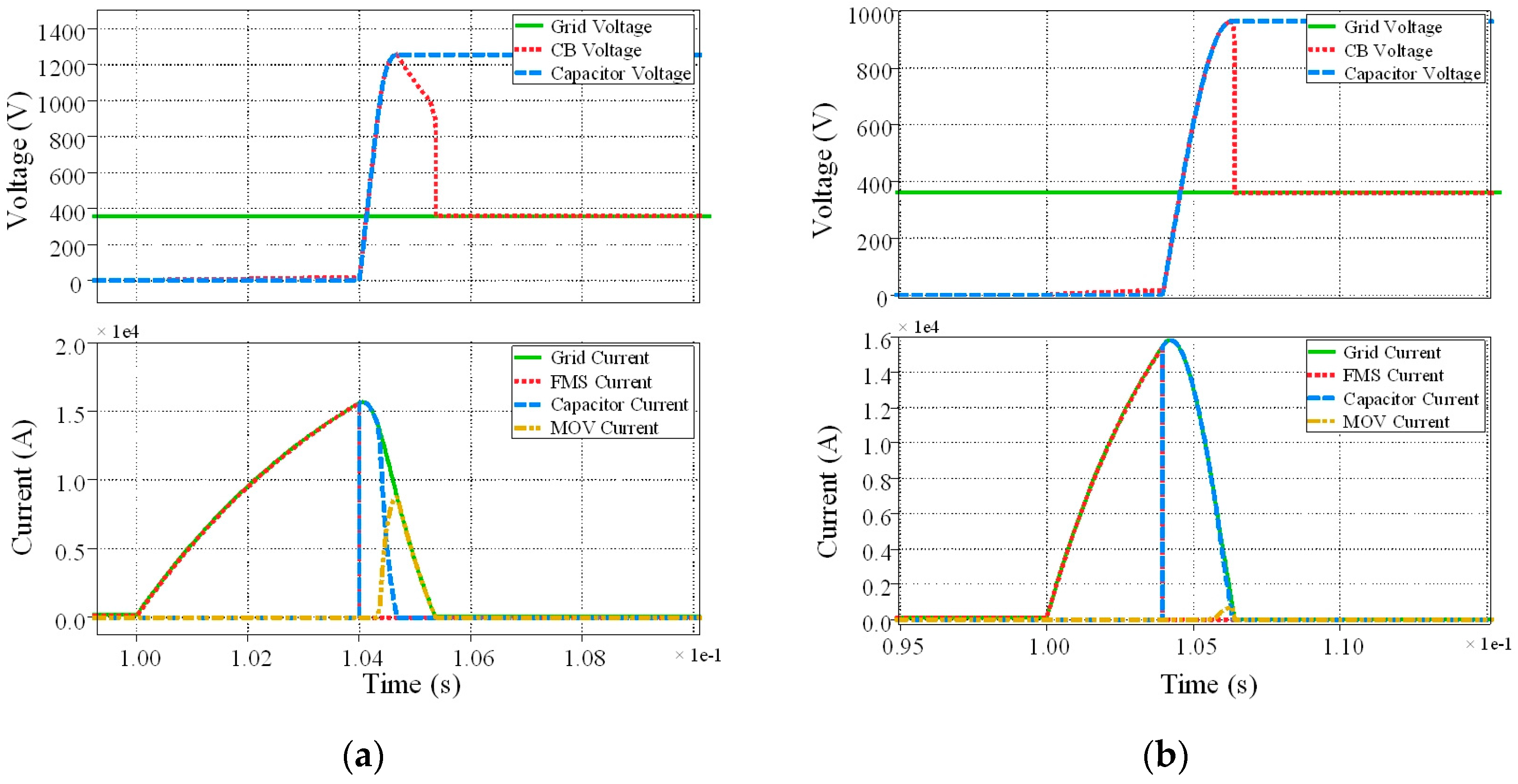
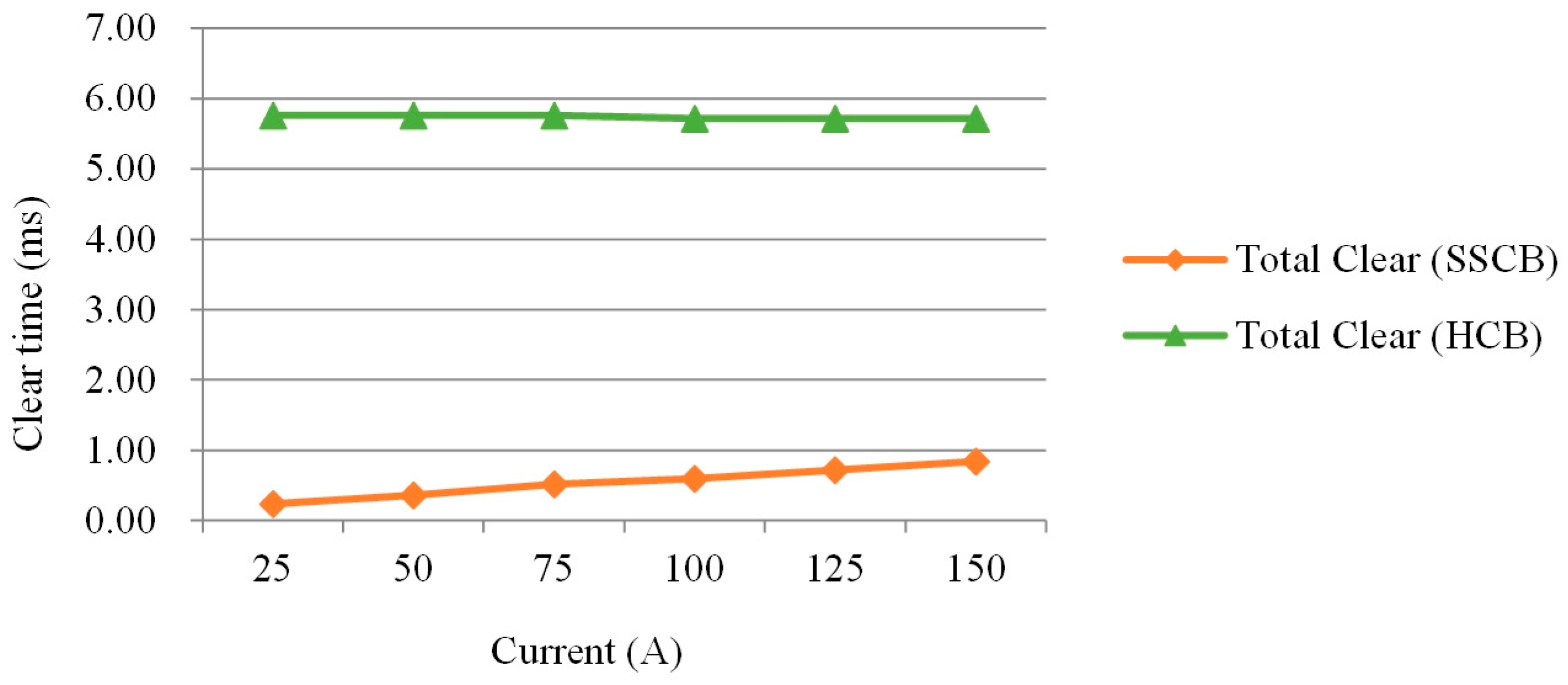
3.2.4. Comparisons of These Configurations

As the tripping time of HCB depends on the speed of a mechanical switch, it is clear that this pure SSCB might be ten times faster than the HCB ones in Figure 31 and Figure 32, and also have a very small peak fault current. Simulations have been done in the PLECS software to check the performance of these three novel CBs. The results of breaking procedure from Configuration 1 to Configuration 3 are shown in Figure 33a–c. The overall comparison of these three configurations is described in Table 2.
Figure 33. Simulation results of breaking procedure of Configuration 1, 2 and 3: (a) Configuration 1; (b) Configuration 2; (c) Configuration 3.
Table 2. Overall summary of the proposed CB configurations with brief comparisons.
It is shown in Table 2 that Configuration 2 suffers from even larger capacitor needs, and accurate FMS trip delay time information is needed to avoid STS overvoltage. Therefore, Configuration 1 (as HCB) and Configuration 3 (as SSCB) are recommended as the proper configuration for CB design. With Configuration 3, symmetrical thyristors could be easily applied to achieve acceptable power losses.
Figure 34 gives a case study (experimental results) of peak current comparison and clear time comparison for HCB (similar to Configuration 1) and SSCB (similar to Configuration 3). In Figure 34a, about 7.8 ms are needed as total clear time, which mainly depends on the trip time of the mechanical switch. The peak current can goes up to about 570 A for 150 A tripping. In Figure 34b, the total clear time is less than 1 ms, and the peak current is just about 150 A. Figure 35 shows the quantitative comparison of total clear time as a further comparison of HCB and SSCB. The ultra-high speed switching is advantageous in peak fault current, total clear time and also equipment non-destruction rate.
Figure 34. Comparison of experimental current waveforms at 150 A tripping: (a) HCB; (b) SSCB.
Figure 35. Comparison of HCB and SSCB: Total clear time.

3.3. Summary of Semiconductor Devices in CB Applications

A case study of semiconductor device in basic SSCB/HCB and three novel configurations is shown in Table 3. For a basic SSCB, by using a SiC MOSFET with third quadrant operation (the same as synchronous rectification), the power loss may be reduced to an acceptable value. SiC bipolar junction transistor (BJT) and SiC junction gate field-effect transistor (JFET) have similar switching and conducting features as SiC MOSFETs.
Table 3. Device examples for 360V DC LV circuit breaker designs.
Thyrisors are good devices as SAS in Configuration 1 and Configuration 2 because of their high pulse current. Compared with GTO and MOS-controlled thyristors (MCTs), thyristors may be the best choice for SMS in Configuration 3 with the lowest on-state loss.

5. Conclusions

In this paper, a review of the current status of SSCB/HCB is first discussed. Increasing amounts of semiconductor devices are being used in SSCB and HCB. SSSC, with no additional heat, controllable current and low current total harmonic distortion (THD), may be a good choice for high performance circuit breakers. Basic SSCB and HCB configurations are investigated with fast-switching analysis and experimental comparisons between SiC MOSFETs and Si IGBTs. Novel control methods, including current limiting with PWM and gate voltage control are described and verified with simulations. It is obvious that with WBG semiconductor devices, basic SSCB and HCB will achieve better performance with higher switching speed and lower system size (lower heat dissipation requirements). Three novel circuit breaker configurations (HCB with capacitor, HCB with STS and capacitor, SSCB with STS and thyristor as SMS) are put forward to further improve the performance of SSCB and HCB. The novel SSCB configuration with STS and thyristor as SMS, with ultra-fast switching speed (microseconds) and acceptable on-state power loss, may be a great choice for medium voltage systems.
In the future, SSCB and HCB with semiconductor devices will be very powerful choices for HVDC/MVDC systems, offering very high speed for medium power low-voltage systems and ultra-high speed switching or multi-functional for low-voltage low power intelligent power grids. WBG semiconductor switching devices will thus win a place in the future circuit breaker family.

Author Contributions

Chunyang Gu, Alan J. Watson and Francis Effah conceived and designed the experiments; Chunyang Gu performed the experiments; Chunyang Gu analyzed the data; Pat Wheeler, Alberto Castellazzi and Alan J. Watson contributed analysis tools and English correction; Chunyang Gu and Francis Effah wrote the paper.

Conflicts of Interest

The authors declare no conflict of interest.

Abbreviations

ABBASEA Brown Boveri Limited Company
ACAlternating current
BJTBipolar Junction Transistor
CBCircuit breaker
CLCurrent-limiting
CL-CBCurrent-limiting circuit breaker
DCDirect current
EPRIElectric Power Research Institute
FCLIDFault-current limiting and interrupting device
FDSFast-opening disconnecting switch
FMSFast mechanical switch
FTSFast-opening transfer switch
GaNGallium nitride
GTOGate turn-off thyristor
HCBHybrid circuit breaker
HCLIDHybrid current-limiting interrupting device
HEMTHigh-electron-mobility transistor
HSSHigh speed switch
HVDCHigh-voltage direct-current
IGBTInsulated-gate bipolar transistor
IGCTIntegrated gate-commutated thyristor
JFETJunction gate field-effect transistor
L-CInductor-capacitor
LCSLine commutation switch
LSLoad switch
LVLow voltage
MCBMechanical circuit breaker
MCCBmolded-case circuit breaker
MCTMOS-controlled thyristor
MDMechanical disconnector
MOSMetal oxide semiconductor
MOSFETMetal-oxide-semiconductor field-effect transistor
MOVMetal oxide varistor
MVMedium voltage
MVDCMedium-voltage direct-current
PTCPositive temperature coefficient
p.u.Per-unit
PWMPulse-width modulation
RCResistor-capacitor
RCDResistor-capacitor-diode
RMSRoot mean square
SASSemiconductor accessary switch
SFCLSuperconductor fault current limiter
SiSilicon
SiCSilicon carbide
SMSSemiconductor main switch
SPICESimulation Program with Integrated Circuit Emphasis
SSCBSolid-state circuit breaker
SSFCLSolid state fault current limiting
SSSCStatic synchronous series compensator
STATCOMStatic synchronous compensator
STSSemiconductor transfer switch
THDTotal harmonic distortion
WBGWide-band-gap
ZCSZero current switching
ZnOZinc oxide

References

  1. Carlson, M.S.; Edmunds, W.H. Co-ordination of current-limiting fuses and low-voltage air circuit breakers. Trans. Am. Inst. Electr. Eng. Part III Power Appar. Syst. 1956, 75, 1038–1048. [Google Scholar]
  2. Brice, C.W.; Dougal, R.A.; Hudgins, J.L. Review of technologies for current-limiting low-voltage circuit breakers. IEEE Trans. Ind. Appl. 1996, 32, 1005–1010. [Google Scholar] [CrossRef]
  3. Meyer, C.; Kowal, M.; De Doncker, R.W. Circuit breaker concepts for future high-power DC-applications. In Proceedings of the Conference Record of the 2005 IEEE Industry Applications Conference, Fourtieth IAS Annual Meeting, Hong Kong, China, 2–6 October 2005; Volume 2, pp. 860–866. [Google Scholar]
  4. Boudreaux, R.R.; Nelms, R.M. A comparison of MOSFETs, IGBTs, and MCTs for solid state circuit breakers. In Proceedings of the Eleventh Annual Applied Power Electronics Conference and Exposition (APEC ′96), San Jose, CA, USA, 3–7 March 1996; Volume 1, pp. 227–233. [Google Scholar]
  5. Meyer, C.; Schroder, S.; De Doncker, R.W. Solid-state circuit breakers and current limiters for medium-voltage systems having distributed power systems. IEEE Trans. Power Electron. 2004, 19, 1333–1340. [Google Scholar] [CrossRef]
  6. Smith, R.K.; Slade, P.G.; Sarkozi, M.; Stacey, E.J.; Bonk, J.J.; Mehta, H. Solid-state distribution current limiter and circuit breaker: Application requirements and control strategies. IEEE Trans. Power Deliv. 1993, 8, 1155–1164. [Google Scholar] [CrossRef]
  7. Atmadji, A.M.S.; Sloot, J.G.J. Hybrid switching: A review of current literature. In Proceedings of the International Conference on Energy Management and Power Delivery (EMPD ′98), Singapore, 3–5 March 1998; Volume 2, pp. 683–688. [Google Scholar]
  8. Paul, W.; Rhyner, J.; Platter, F. Superconducting fault current limiters based on high Tc superconductors. In Proceedings of the IEE Colloquium on Fault Current Limiters—A Look at Tomorrow, London, UK, 8 June 1995; pp. 1–4. [Google Scholar]
  9. Abri, A.; Nordgren, R.; Kjellnas, S.; Banghammar, L.; Lindgren, S. Finite element analysis of electromagnets and contact systems in low voltage current limiting circuit breakers. IEEE Trans. Magn. 1990, 26, 960–963. [Google Scholar] [CrossRef]
  10. Abri, A.; Kjellnas, S.; Nordgren, R.; Lindgren, S.; Banghammar, L.A. Mechanism of interaction between electric arc and breaking chamber in low voltage current limiting circuit breakers. IEEE Trans. Ind. Appl. 1991, 27, 841–848. [Google Scholar] [CrossRef]
  11. Huaren, W.; Ling, Y.; Lin, S.; Xiaohui, L. Modeling of Current-Limiting Circuit Breakers for the Calculation of Short-Circuit Current. IEEE Trans. Power Deliv. 2015, 30, 652–656. [Google Scholar]
  12. Genji, T.; Nakamura, O.; Isozaki, M.; Yamada, M.; Morita, T.; Kaneda, M. 400 V class high-speed current limiting circuit breaker for electric power system. IEEE Trans. Power Deliv. 1994, 9, 1428–1435. [Google Scholar] [CrossRef]
  13. Meyer, J.M.; Rufer, A. A DC hybrid circuit breaker with ultra-fast contact opening and integrated gate-commutated thyristors (IGCTs). IEEE Trans. Power Deliv. 2006, 21, 646–651. [Google Scholar] [CrossRef]
  14. Gregory, G.D.; Hall, W.M. Predicting molded-case circuit breaker let-through characteristics in an electrical system under short-circuit conditions. IEEE Trans. Ind. Appl. 1993, 29, 548–556. [Google Scholar] [CrossRef]
  15. McBride, J.W.; Weaver, P.M. Review of arcing phenomena in low voltage current limiting circuit breakers. IEE Proc. Sci. Meas. Technol. 2001, 148, 1–7. [Google Scholar] [CrossRef]
  16. McBride, J.W.; Pechrach, K.; Weaver, P.M. Arc motion and gas flow in current limiting circuit breakers operating with a low contact switching velocity. IEEE Trans. Compon. Packag. 2002, 25, 427–433. [Google Scholar] [CrossRef]
  17. Tahiliani, V.H.; Porter, J.W. Fault Current Limiters an Overview of EPRI Research. IEEE Trans. Power Appar. Syst. 1980, PAS-99, 1964–1969. [Google Scholar] [CrossRef]
  18. Kishida, Y.; Koyama, K.; Sasao, H.; Maruyama, N.; Yamamoto, H. Development of the high speed switch and its application. In Proceedings of the Thirty-Third IEEE Industry Applications Conference IAS Annual Meeting, St. Louis, MO, USA, 12–15 October 1998; Volume 3, pp. 2321–2328. [Google Scholar]
  19. Uezono, H.; Takemoto, Y.; Yuya, M.; Kado, H. Development of a fault current limiter for 22 kV distribution system. In Proceedings of the IEEE 9th International Conference on Transmission and Distribution Construction, Operation and Live-Line Maintenance (ESMO), Montreal, QC, Canada, 8–12 October 2000; pp. 239–244. [Google Scholar]
  20. Yamaguchi, S. Circuit Breaker. U.S. Patent 20090201617 A1, 13 August 2009. [Google Scholar]
  21. Steurer, M.; Frohlich, K.; Holaus, W.; Kaltenegger, K. A novel hybrid current-limiting circuit breaker for medium voltage: Principle and test results. IEEE Trans. Power Deliv. 2003, 18, 460–467. [Google Scholar] [CrossRef]
  22. Lee, B.W.; Sim, J.; Park, K.B.; Oh, I.S. Practical Application Issues of Superconducting Fault Current Limiters for Electric Power Systems. IEEE Trans. Appl. Supercond. 2008, 18, 620–623. [Google Scholar] [CrossRef]
  23. Neumueller, H.W.; Schmidt, W.; Kraemer, H.P.; Otto, A.; Maguire, J.; Jie, Y.; Folts, D.; Romanosky, W.; Gamble, B.; Madura, D.; et al. Development of Resistive Fault Current Limiters Based on YBCO Coated Conductors. IEEE Trans. Appl. Supercond. 2009, 19, 1950–1955. [Google Scholar] [CrossRef]
  24. Bin, X.; Zhiyuan, L.; Yingsan, G.; Yanabu, S. DC Circuit Breaker Using Superconductor for Current Limiting. IEEE Trans. Appl. Supercond. 2015, 25, 1–7. [Google Scholar]
  25. Amir Khan, U.; Lee, J.; Amir, F.; Lee, B. A Novel Model of HVDC Hybrid-Type Superconducting Circuit Breaker and Its Performance Analysis for Limiting and Breaking DC Fault Currents. IEEE Trans. Appl. Supercond. 2015, 25, 1–9. [Google Scholar] [CrossRef]
  26. Lee, B.W.; Park, K.B. Complex Superconducting Fault Current Limiter. U.S. Patent 20080043382 A1, 21 February 2008. [Google Scholar]
  27. Power, A.J. An overview of transmission fault current limiters. In Proceedings of the IEE Colloquium on Fault Current Limiters—A Look at Tomorrow, London, UK, 8 June 1995; pp. 1–5. [Google Scholar]
  28. Min Cheol, A.; Seungje, L.; Hyoungku, K.; Duck Kwoen, B.; Minseok, J.; Hyun Seok, K.; Tae Kuk, K. Design, fabrication and test of high-Tc superconducting DC reactor for inductive superconducting fault current limiter. IEEE Trans. Appl. Supercond. 2004, 14, 827–830. [Google Scholar]
  29. Peelo, D.F.; Polovick, G.S.; Sawada, J.H.; Diamanti, P.; Presta, R.; Sarshar, A.; Beauchemin, R. Mitigation of circuit breaker transient recovery voltages associated with current limiting reactors. IEEE Trans. Power Deliv. 1996, 11, 865–871. [Google Scholar] [CrossRef]
  30. Radmanesh, H.; Fathi, S.H.; Gharehpetian, G.B.; Heidary, A. Bridge Type Solid State Fault Current Limiter Based on AC/DC Reactor. IEEE Trans. Power Deliv. 2015, 31, 200–209. [Google Scholar] [CrossRef]
  31. Czucha, J.; Lipski, T.; Zyborski, J. Hybrid current limiting interrupting device for 3-phase 400 V AC applications, Trends in Distribution Switchgear. In Proceedings of the Fifth International Conference on Trends in Distribution Switchgear: 400 V–145 kV for Utilities and Private Networks, London, UK, 10–12 November 1998; pp. 161–166. [Google Scholar]
  32. Zyborski, J.; Lipski, T.; Czucha, J.; Hasan, S. Hybrid arcless low-voltage AC/DC current limiting interrupting device. IEEE Trans. Power Deliv. 2000, 15, 1182–1187. [Google Scholar] [CrossRef]
  33. Schroder, S.; Meyer, C.; De Doncker, R.W. Solid-state circuit breakers and current-limiting devices for medium-voltage systems. In Proceedings of the VIII IEEE International Power Electronics Congress (CIEP 2002), Technical Proceedings, Piscataway, NJ, USA, 20–24 October 2002; pp. 91–95. [Google Scholar]
  34. Demetriades, G.; Shukla, A. Hybrid Circuit Breaker. U.S. Patent 20120218676 A1, 30 August 2012. [Google Scholar]
  35. Radmanesh, H.; Fathi, S.H.; Gharehpetian, G.B.; Heidary, A. A Novel Solid-State Fault Current-Limiting Circuit Breaker for Medium-Voltage Network Applications. IEEE Trans. Power Deliv. 2015, 31, 236–244. [Google Scholar] [CrossRef]
  36. Ahmed, M.M.R.; Putrus, G.; Li, R.; Penlington, R. Development of a prototype solid-state fault-current limiting and interrupting device for low-voltage distribution networks. IEEE Trans. Power Deliv. 2006, 21, 1997–2005. [Google Scholar] [CrossRef]
  37. Maitra, A.; McGranaghan, M.; Lai, J.S.; Short, T.; Goodman, F. Multifunction Hybrid Solid-State Switchgear. U.S. Patent 7405910 B2, 29 July 2008. [Google Scholar]
  38. Kapoor, R.; Shukla, A. Modelling and control of a hybrid circuit breaker with fault current limiting ability. In Proceedings of the 2012 IEEE International Conference on Power Electronics, Drives and Energy Systems (PEDES), Bengaluru, India, 16–19 December 2012; pp. 1–6. [Google Scholar]
  39. Hassanpoor, A.; Hafner, J.; Jacobson, B. Technical Assessment of Load Commutation Switch in Hybrid HVDC Breaker. IEEE Trans. Power Electron. 2015, 30, 5393–5400. [Google Scholar] [CrossRef]
  40. Gang, C.; Daozhuo, J.; Zhaolin, W.; Zhengyu, L. Simulation study of bridge type solid state fault current limiter. In Proceedings of the 2003 IEEE Power Engineering Society General Meeting, Toronto, ON, Canada, 13–17 July 2003; Volume 4, pp. 2521–2526. [Google Scholar]
  41. Zhengyu, L.; Daozhou, J.; Zhaolin, W. A new topology of fault-current limiter and its parameters optimization. In Proceedings of the IEEE 34th Annual Power Electronics Specialist Conference (PESC ′03), Acapulco, Mexico, 15–19 June 2003; Volume 1, pp. 462–465. [Google Scholar]
  42. Wanmin, F.; Yanli, Z. A novel IGCT-based Half-controlled Bridge Type Fault Current Limiter. In Proceedings of the CES/IEEE 5th International Power Electronics and Motion Control Conference (IPEMC 2006), Shanghai, China, 14–16 August 2006; Volume 2, pp. 1–5. [Google Scholar]
  43. Duangkamol, K.; Mitani, Y.; Tsuji, K.; Hojo, M. Fault current limiting and power system stabilization by static synchronous series compensator. In Proceedings of the International Conference on Power System Technology (PowerCon 2000), Perth, Australia, 4–7 December 2000; Volume 3, pp. 1581–1586. [Google Scholar]
  44. Farmad, M.; Farhangi, S.; Afsharnia, S.; Gharehpetian, G.B. Modelling and simulation of voltage source converter-based interphase power controller as fault-current limiter and power flow controller. IET Gener. Transm. Distrib. 2011, 5, 1132–1140. [Google Scholar] [CrossRef]
  45. Saradarzadeh, M.; Farhangi, S.; Schanen, J.L.; Jeannin, P.O.; Frey, D. Combination of power flow controller and short-circuit limiter in distribution electrical network using a cascaded H-bridge distribution-static synchronous series compensator. IET Gener. Transm. Distrib. 2012, 6, 1121–1131. [Google Scholar] [CrossRef]
  46. Zafari, M.; Gholipour, E.; Madani, S.M. Active fault current limiter and comparison of its performance with SFCL. In Proceedings of the 9th Power Systems Protection and Control Conference (PSPC), Glasgow, UK, 14–15 January 2015; pp. 31–35. [Google Scholar]
  47. Gyugyi, L.; Schauder, C.D.; Sen, K.K. Static synchronous series compensator: A solid-state approach to the series compensation of transmission lines. IEEE Trans. Power Deliv. 1997, 12, 406–417. [Google Scholar] [CrossRef]
  48. Choi, S.S.; Wang, T.X.; Vilathgamuwa, D.M. A series compensator with fault current limiting function. IEEE Trans. Power Deliv. 2005, 20, 2248–2256. [Google Scholar] [CrossRef]
  49. Gu, C.; Wheeler, P.; Castellazzi, A.; Watson, A.J.; Effah, F. A survey on configurations of current-limiting circuit breakers (CL-CB). In Proceedings of the 18th European Conference on Power Electronics and Applications (EPE ′16 ECCE Europe), Karlsruhe, Germany, 5–9 September 2016; pp. 1–13. [Google Scholar]
  50. Ranjan, R.; Kalkstein, E.W. Design, development and application of smart fuses—Part 1. IEEE Trans. Ind. Appl. 1994, 30, 164–169. [Google Scholar] [CrossRef]
  51. IEEE Application Guide for Low-Voltage AC Power Circuit Breakers Applied with Separately-Mounted Current-Limiting Fuses; IEEE Std C37.27–2008 (Revision of IEEE Std C37.27–1987); IEEE: New York, NY, USA, 2009; pp. 1–20.
  52. Papallo, T.; Valdes, M.; Roscoe, G. Predicting Let-Through Arc-Flash Energy for Current-Limiting Circuit Breakers. IEEE Trans. Ind. Appl. 2010, 46, 1820–1826. [Google Scholar] [CrossRef]
  53. Chang, P.; Huang, A.Q.; Xiaoqing, S. Current commutation in a medium voltage hybrid DC circuit breaker using 15 kV vacuum switch and SiC devices. In Proceedings of the 2015 IEEE Applied Power Electronics Conference and Exposition (APEC), Charlotte, NC, USA, 15–19 March 2015; pp. 2244–2250. [Google Scholar]

Article Metrics

Citations

Article Access Statistics

Multiple requests from the same IP address are counted as one view.