
A Model-Based Approach to Automated Validation and Generation of PLC Code for Manufacturing Equipment in Regulated Environments

 ,
, 
Abstract
:1. Introduction
2. Background
2.1. Equipment Validation Practices in Regulated Industries
2.2. Industry 4.0
- Interconnection
- Information transparency
- Technical assistance
- Decentralised decisions
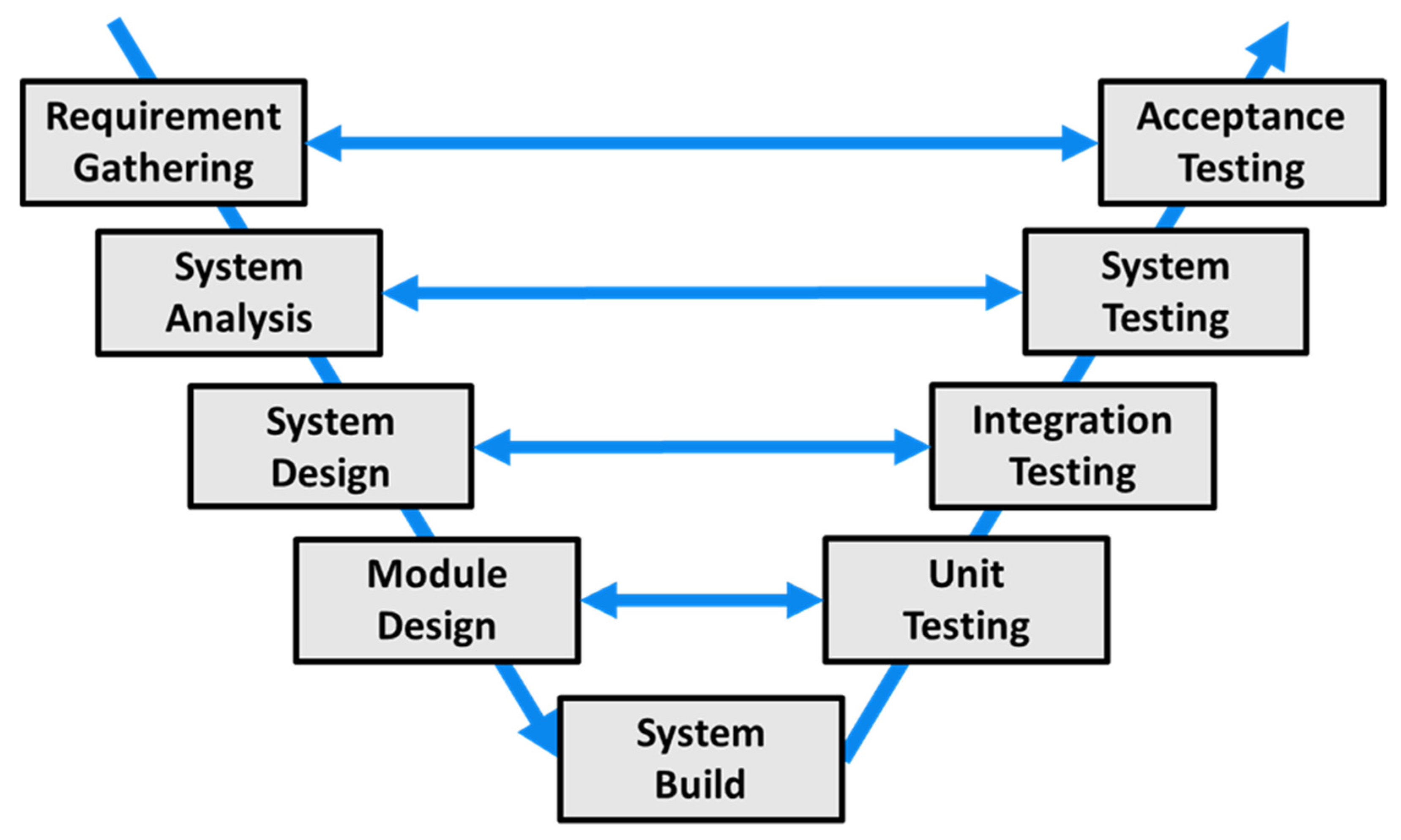
2.3. Model-Based Design
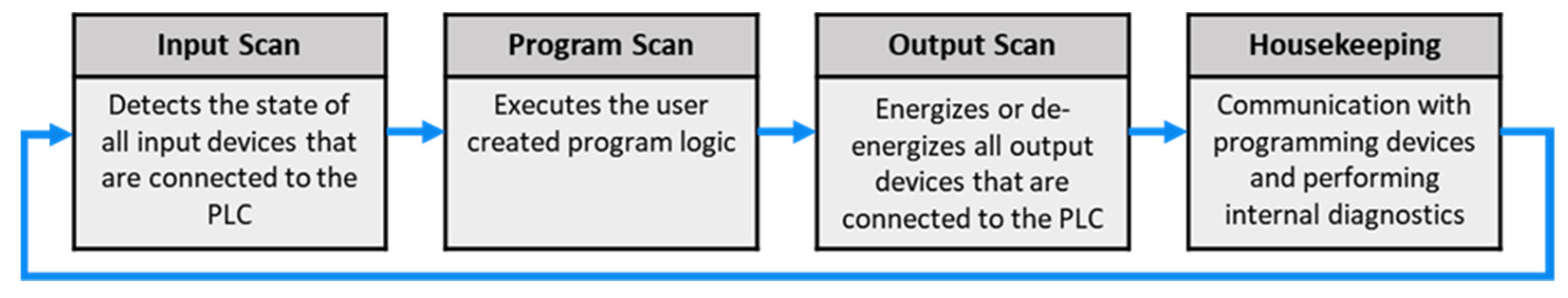
2.4. Equipment Control and Programmable Logic Controllers
2.5. Model Checking of PLC Code
3. Methodology
3.1. Proposed Methodology
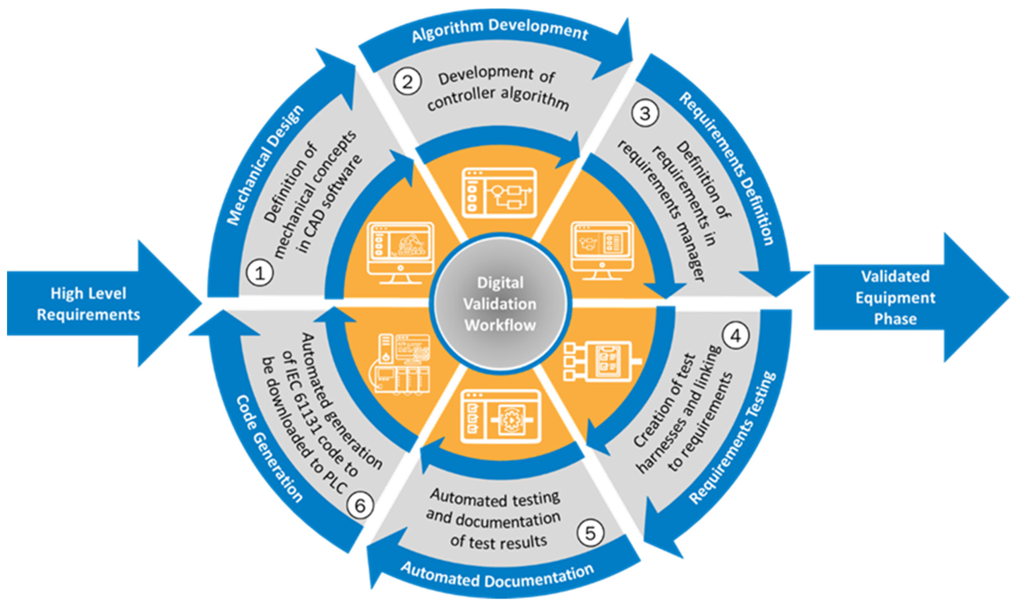
3.2. Digital Validation Workflow
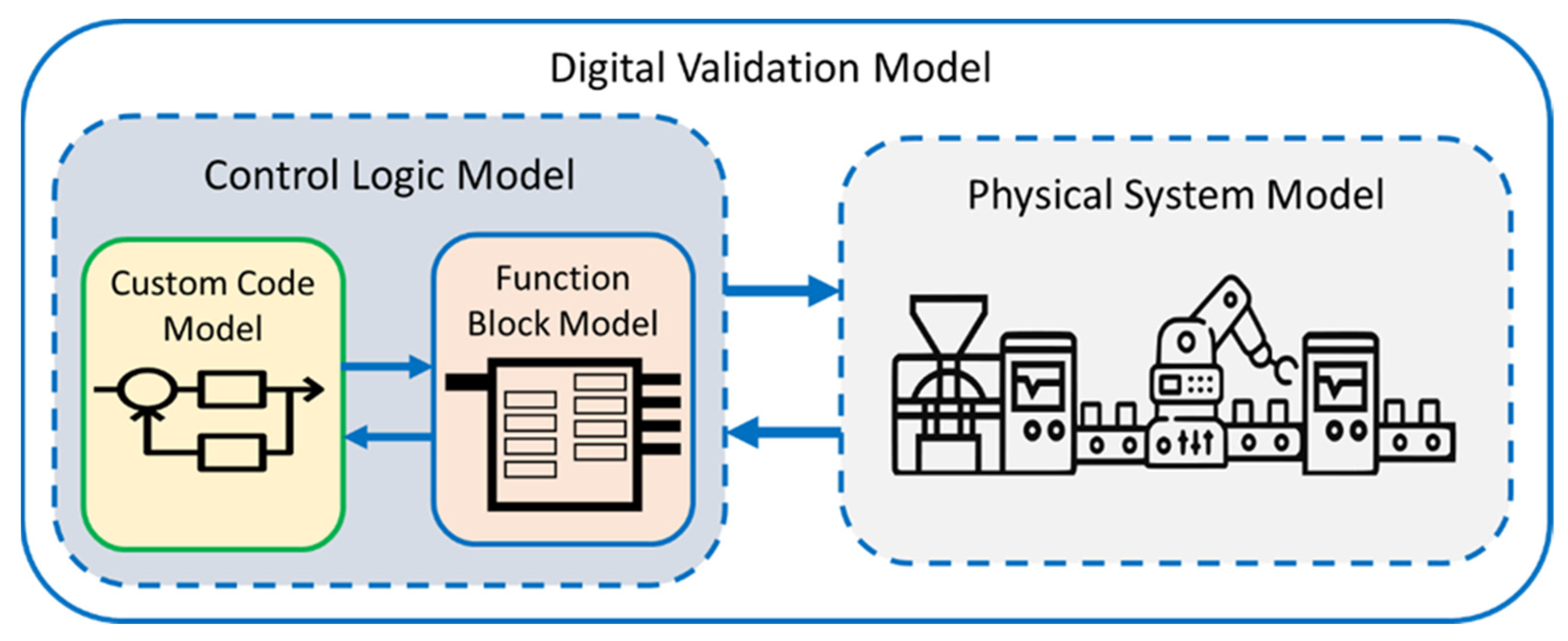
3.3. Methodology Development and Modelling Approach
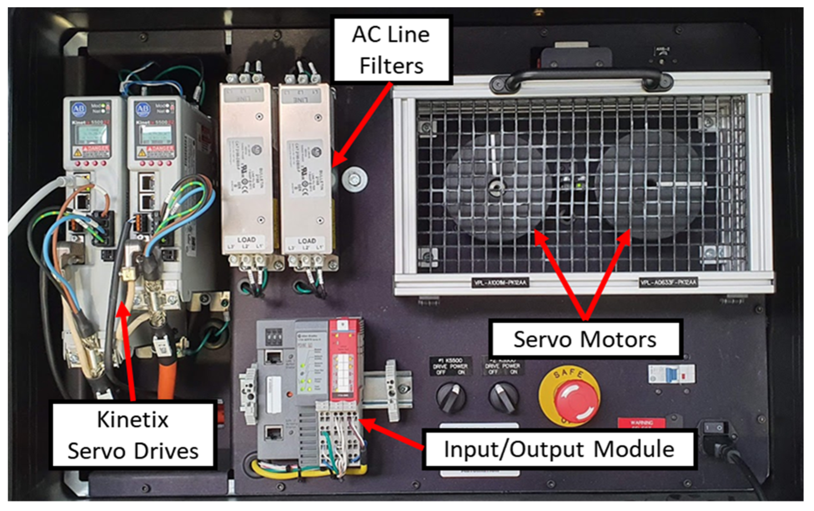
3.4. Experimental Setup and Application Description
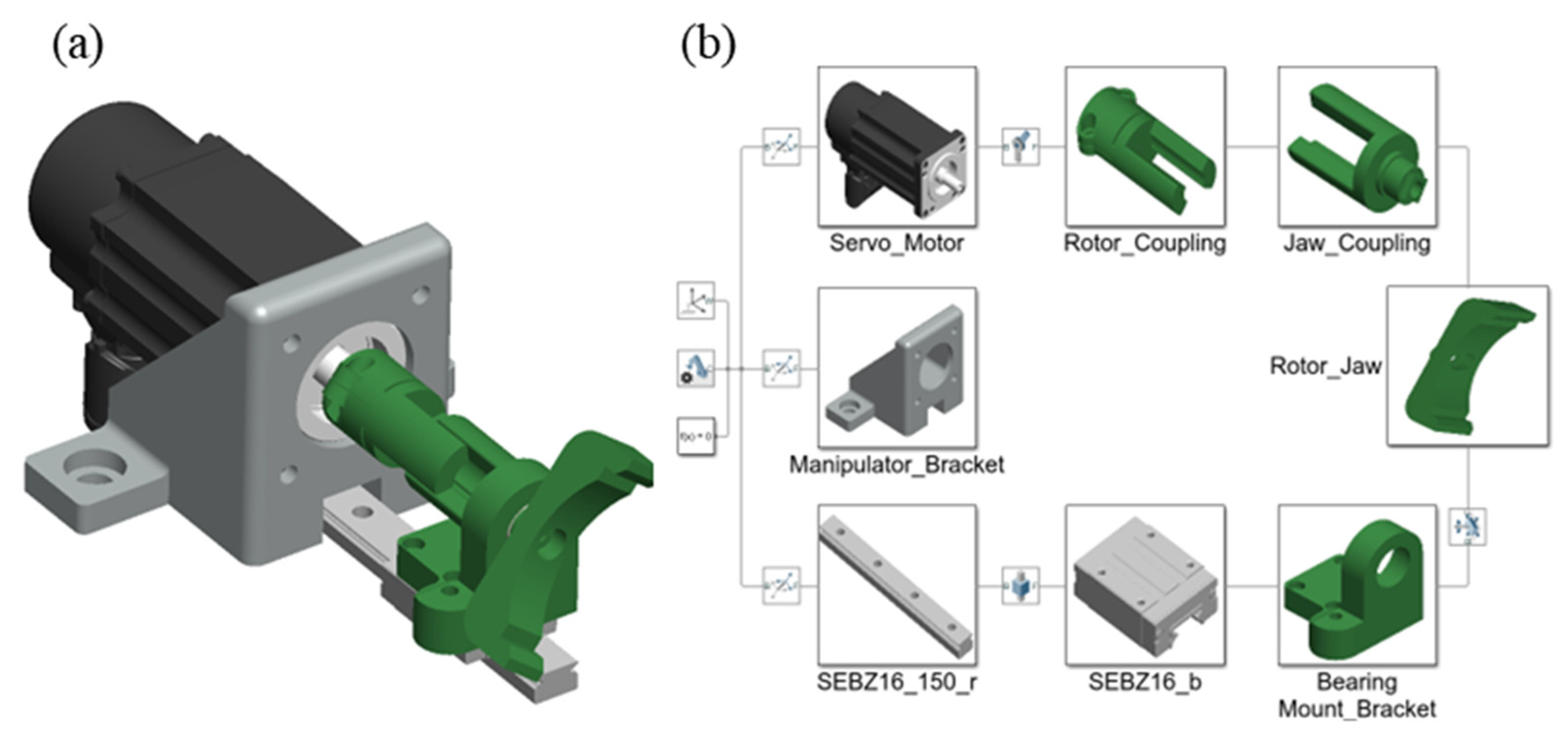
3.5. Physical System Model Development
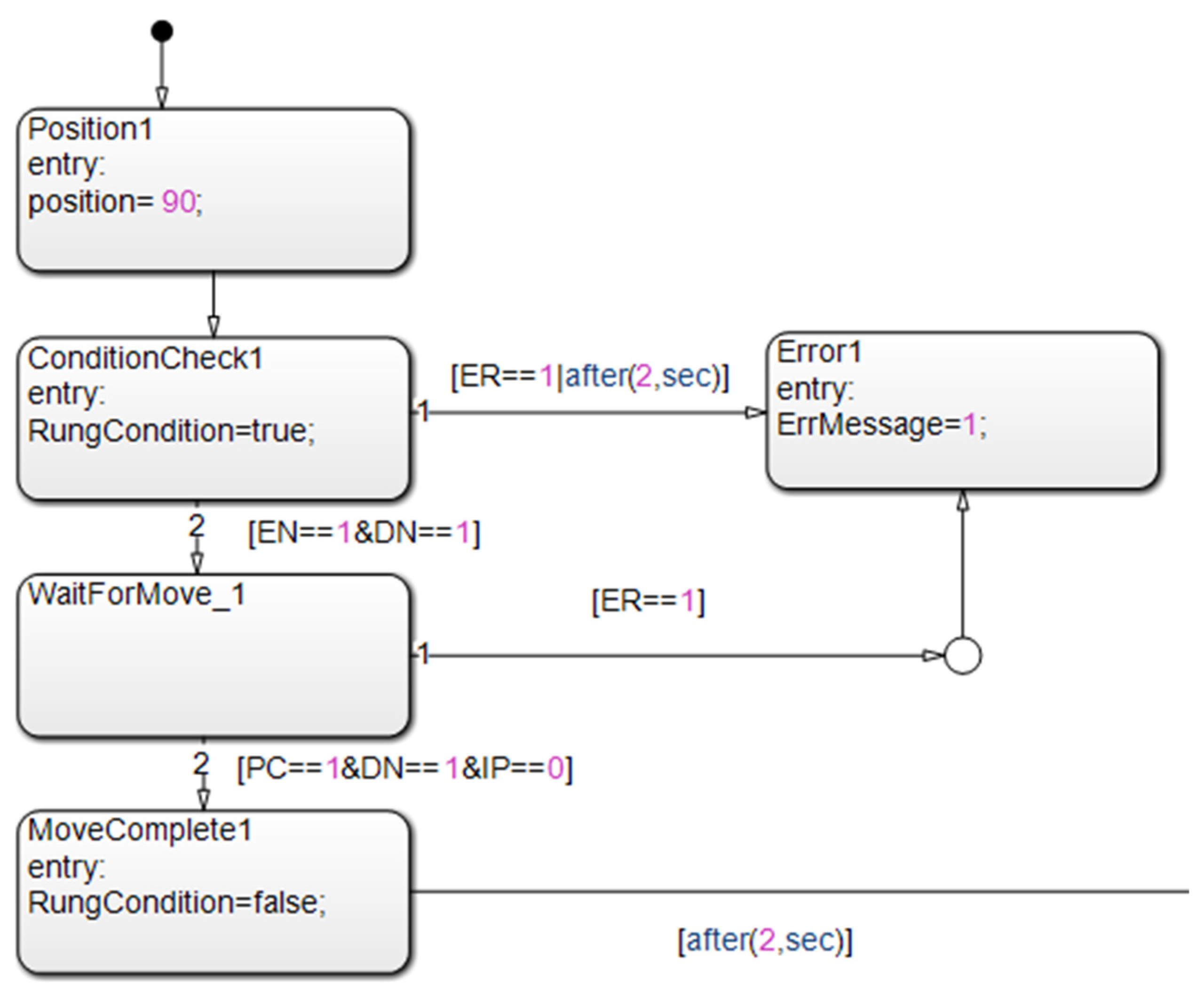
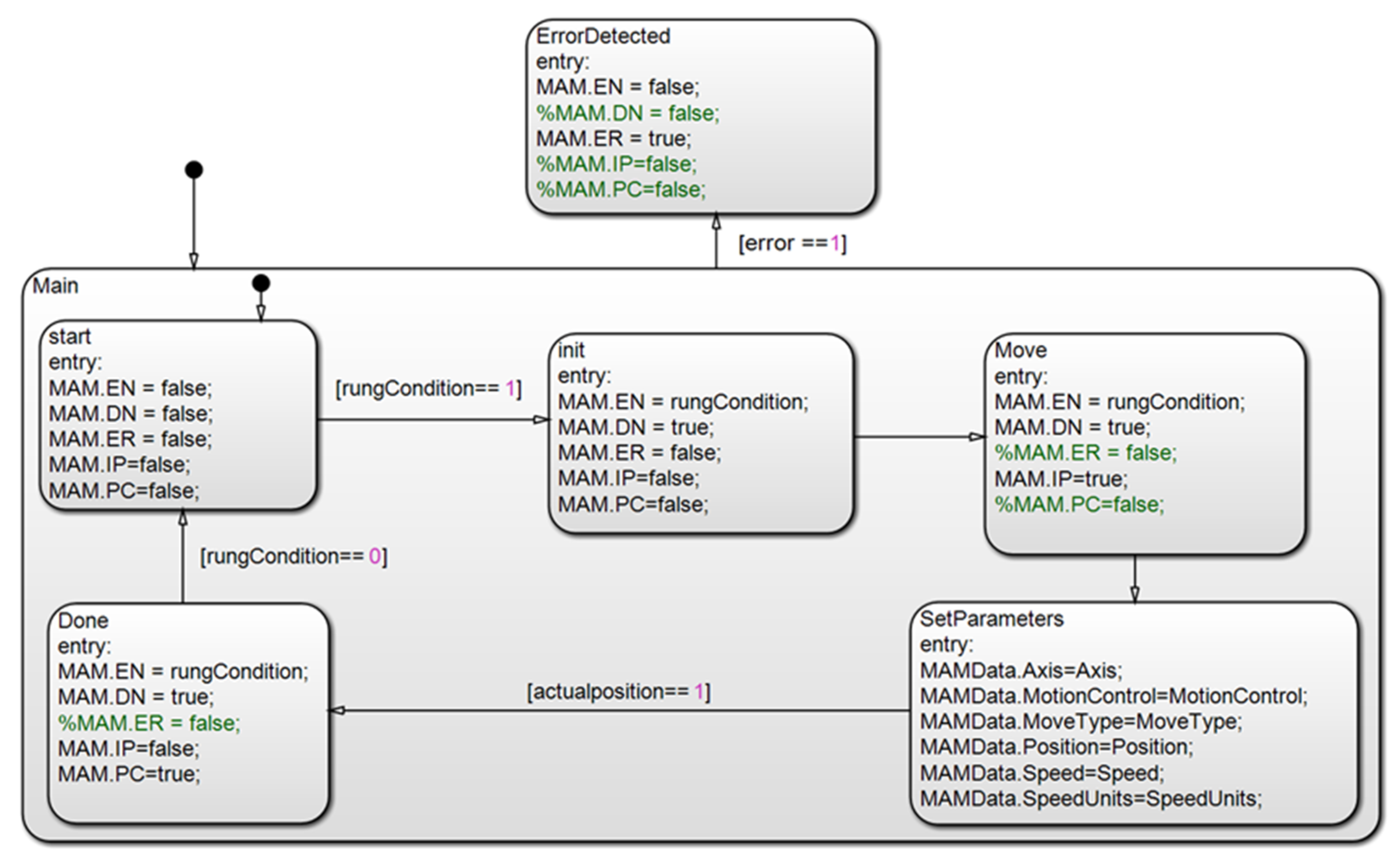
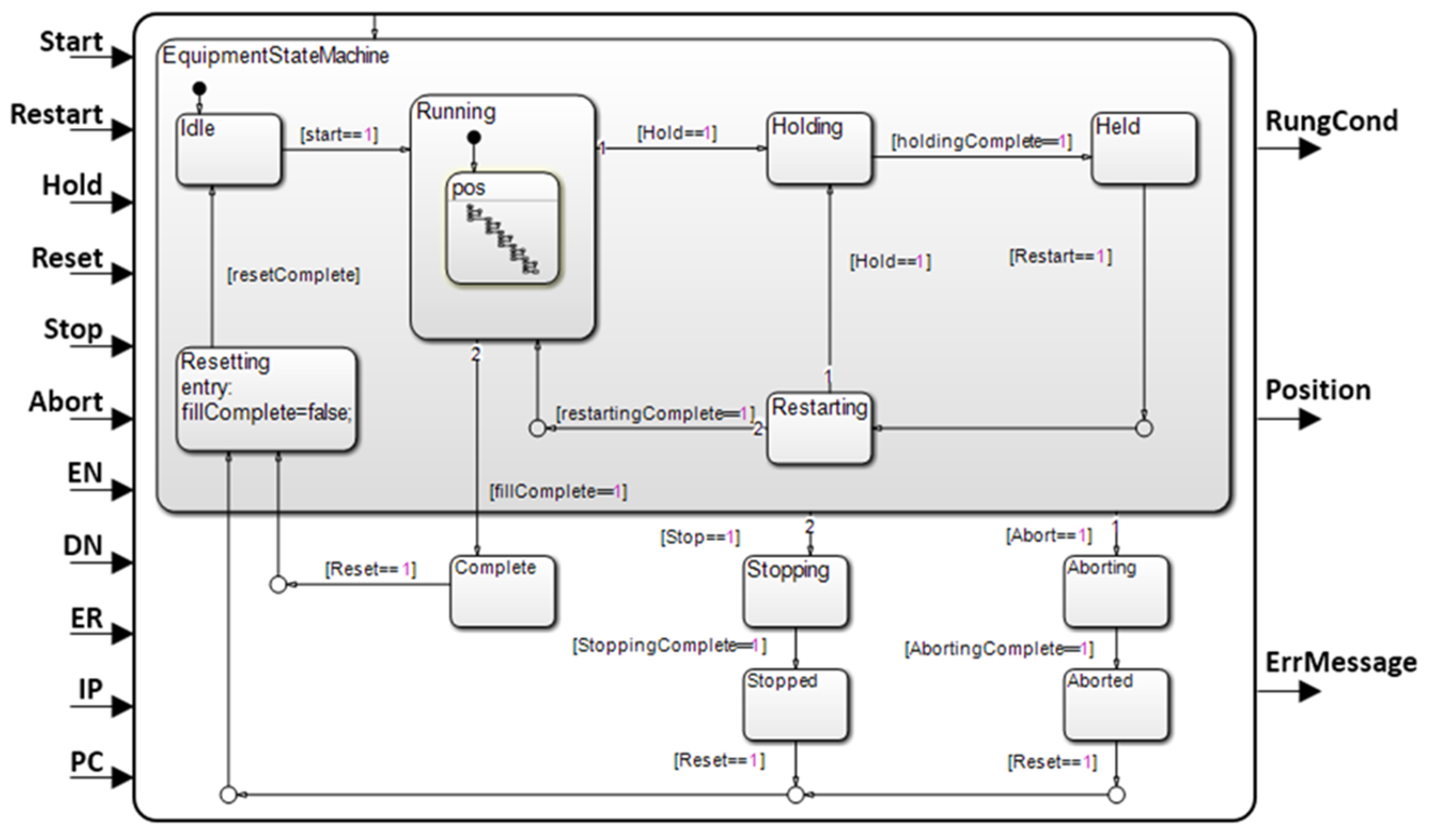
3.6. Control Logic Model Development
3.7. Definition of Requirements and Automated Testing
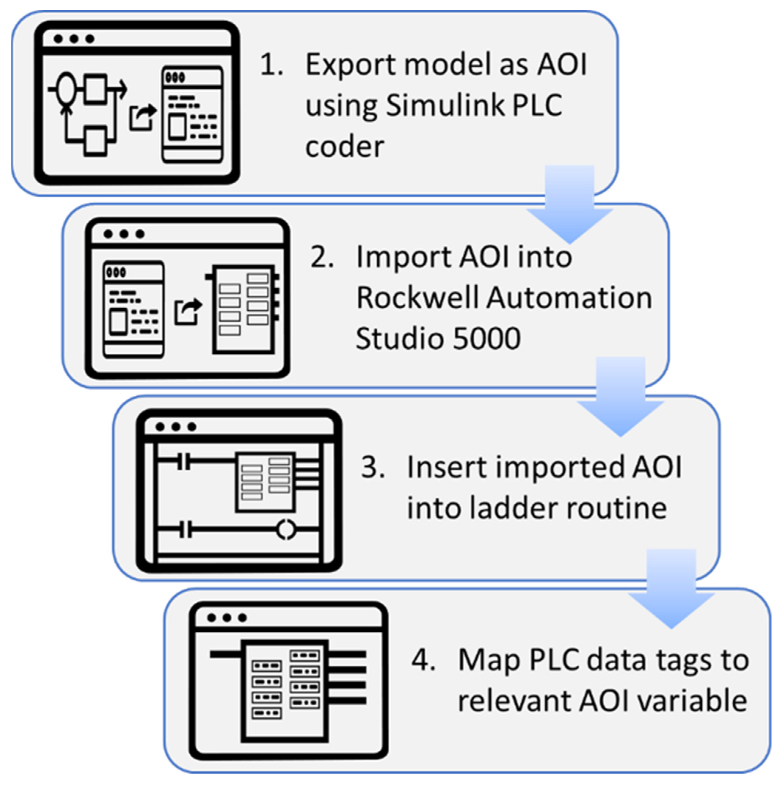
3.8. Automated PLC Code Generation and Operation on the Physical Equipment
4. Results
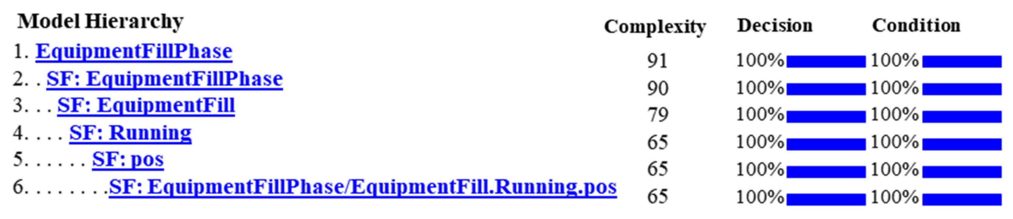
4.1. Results of Automated Testing and Report Generation
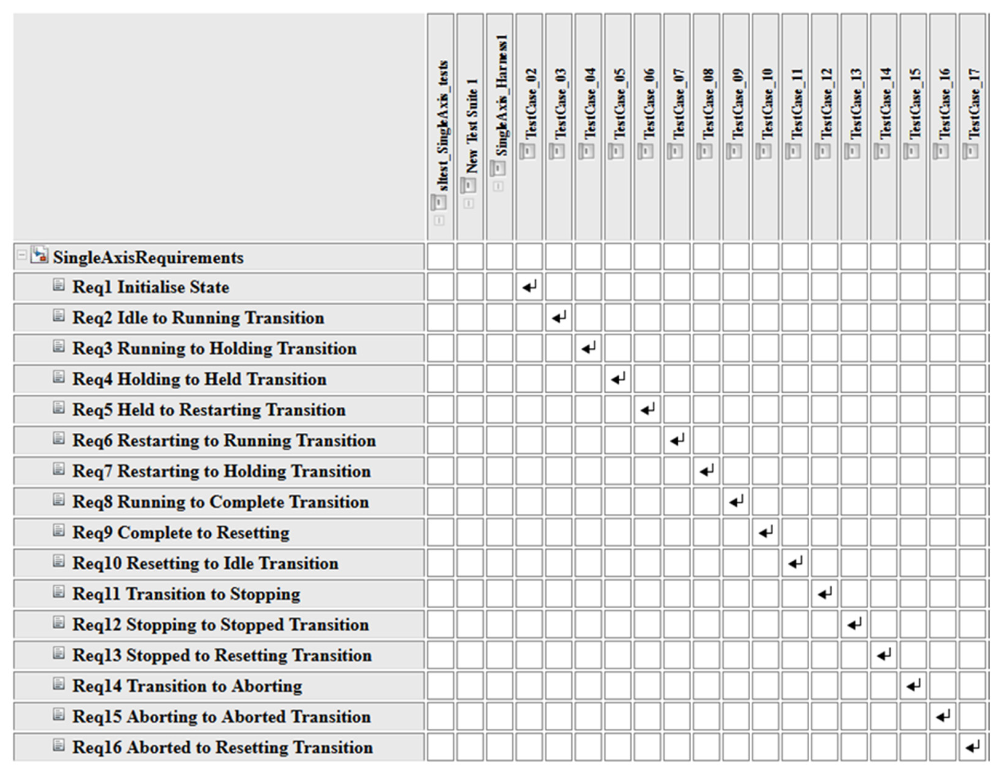
4.2. Traceability between Tests and Requirements
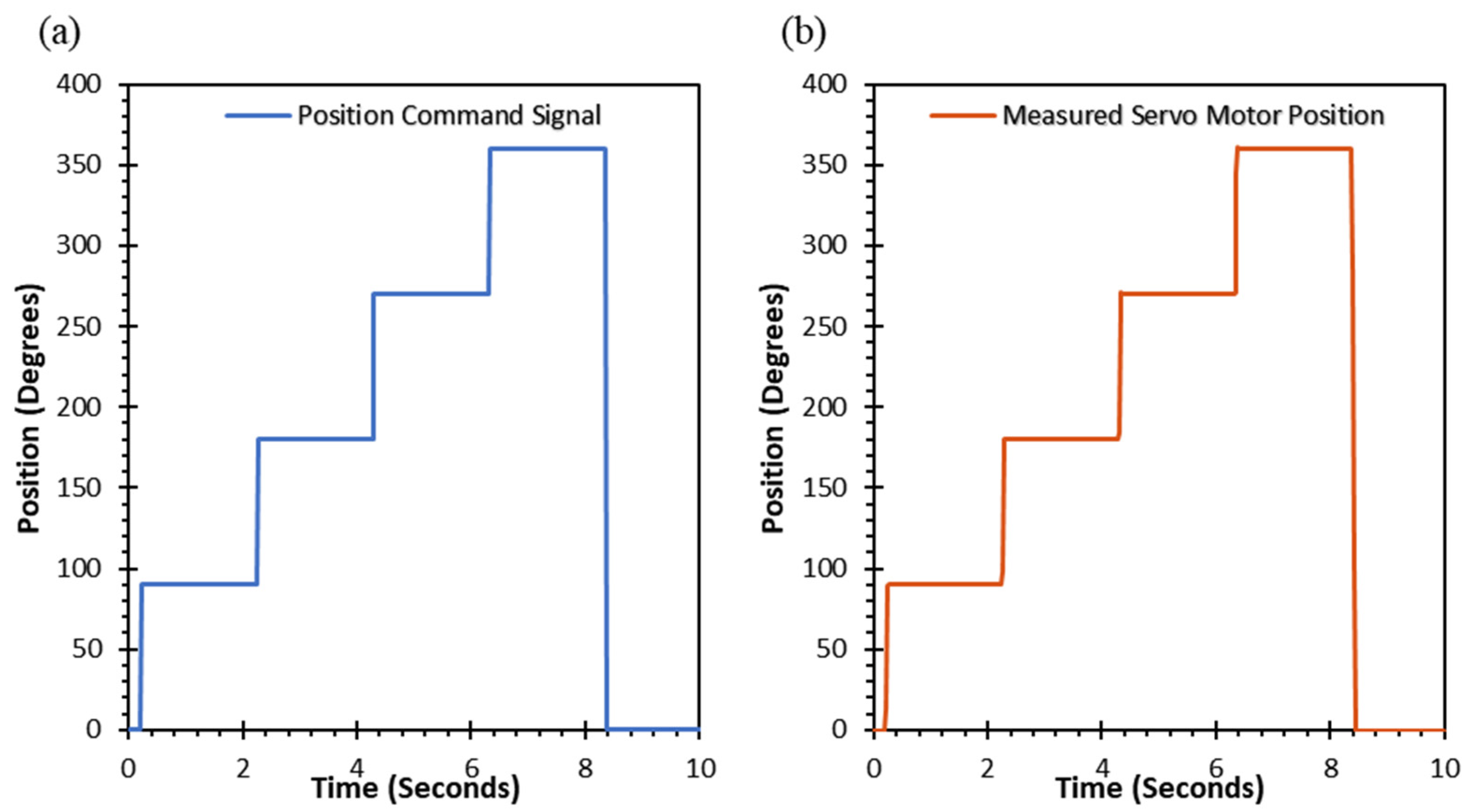
4.3. Operation of the Code on the Physical Equipment
5. Discussion
6. Conclusions
Author Contributions
Funding
Institutional Review Board Statement
Informed Consent Statement
Data Availability Statement
Acknowledgments
Conflicts of Interest
Appendix A

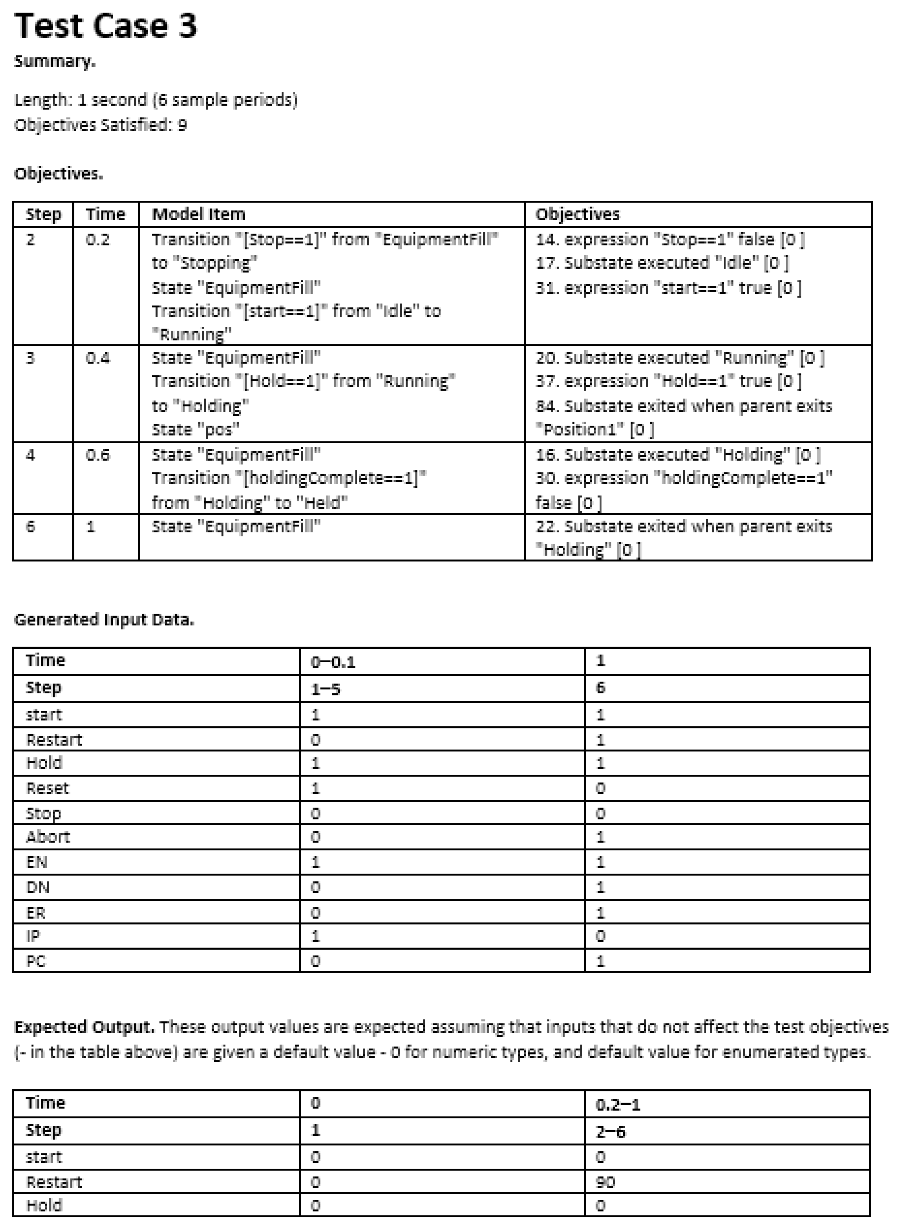
- Explanation:
- This is an example of a test case.
- This test case satisfies Requirement 2–Idle to Running Transition.
- The objectives table is a list of the model elements which were tested in this case and the associated test objective that this test case satisfied.
- The Generated Input Data table records the value of each model input at every simulation step of the test case.
- The Expected Output Table presents the expected simulation output values for this test case.
References
- Food and Drug Administration. Process Validation: General Principles and Practices; U.S. Department of Health and Human Services: Washington, DC, USA, 2011.
- Margetts, D.; Vuolo, M. Breaking with Tradition: Laying the Foundation for Validation 4.0. Available online: https://ispe.org/pharmaceutical-engineering/march-april-2021/breaking-tradition-laying-foundation-validation-40 (accessed on 9 December 2021).
- Weyer, S.; Schmitt, M.; Ohmer, M.; Gorecky, D. Towards Industry 4.0—Standardization as the crucial challenge for highly modular, multi-vendor production systems. IFAC-PapersOnLine 2015, 48, 579–584. [Google Scholar] [CrossRef]
- Aheleroff, S.; Philip, R.; Zhong, R.Y.; Xu, X. The Degree of Mass Personalisation under Industry 4.0. Procedia CIRP 2019, 81, 1394–1399. [Google Scholar] [CrossRef]
- Cohen, Y.; Faccio, M.; Galizia, F.G.; Mora, C.; Pilati, F. Assembly system configuration through Industry 4.0 principles: The expected change in the actual paradigms. IFAC-PapersOnLine 2017, 50, 14958–14963. [Google Scholar] [CrossRef]
- Yu, J.; Yin, Y.; Sheng, X.; Chen, Z. Modelling strategies for reconfigurable assembly systems. Assem. Autom. 2003, 23, 266–272. [Google Scholar] [CrossRef]
- Thramboulidis, K. The 3+1 SysML View-Model in Model Integrated Mechatronics. J. Softw. Eng. Appl. 2010, 3, 109–118. [Google Scholar] [CrossRef] [Green Version]
- Vogel-Heuser, B.; Feldman, S.; Folmer, J.; Ladiges, J.; Fay, A.; Lity, S.; Tichy, M.; Kowal, M.; Schaefer, I.; Haubeck, C.; et al. Selected challenges of software evolution for automated production systems. In Proceedings of the 015 IEEE 13th International Conference on Industrial Informatics (INDIN), Cambridge, UK, 22–24 July 2015; pp. 314–321. [Google Scholar]
- Ståhl, J.; Gabrielson, P.; Andersson, C.; Jönsson, M. Dynamic manufacturing costs—Describing the dynamic behavior of downtimes from a cost perspective. CIRP J. Manuf. Sci. Technol. 2012, 5, 284–295. [Google Scholar] [CrossRef]
- U.S. Food and Drug Administration. International Medical Device Regulators Forum. Available online: https://www.fda.gov/medical-devices/cdrh-international-programs/international-medical-device-regulators-forum-imdrf (accessed on 15 November 2021).
- ISPE. What Is GMP? Available online: https://ispe.org/initiatives/regulatory-resources/gmp/what-is-gmp (accessed on 15 November 2021).
- ISPE. GAMP® 5: A Risk-Based Approach to Compliant GxP Computerized Systems; International Society for Pharmaceutical Engineering: Tampa, FL, USA, 2008. [Google Scholar]
- International Society for Pharmaceutical Engineering. What Is GAMP? Available online: https://ispe.org/initiatives/regulatory/what-gamp (accessed on 30 March 2022).
- Fanmuy, G.; Szczepaniak, R. Requirements Engineering in the bio medical industry: GAMP 5 and tooling. INCOSE Int. Symp. 2010, 20, 2430–2445. [Google Scholar] [CrossRef]
- Margetts, A.J.; Lundsberg-Nielsen, L. The History & Future of Validation. Available online: https://ispe.org/pharmaceutical-engineering/march-april-2021/history-future-validation (accessed on 19 November 2021).
- Engel, A. Systems Quality Costs in the Literature. In Verification, Validation, and Testing of Engineered Systems; John Wiley & Sons: Hoboken, NJ, USA, 2010. [Google Scholar]
- Bennet, C.; Heesakkers, H.; Horneborg, S.; Langer, G.; Lundsberg-Nielsen, L.; Margetts, A.; Roder, F. Industry Perspective: Validation 4.0—Shifting Paradigms. 2020. Available online: https://ispe.org/pharmaceutical-engineering/november-december-2020/industry-perspective-validation-40-shifting (accessed on 21 November 2021).
- Kagerman, H.; Wahlster, W.; Helbig, J. Recommendations for Implementing the Strategic Initiative INDUSTRIE 4.0; Final Report of the Industrie 4.0 Working Group: Frankfurt, Germany, 2013. [Google Scholar]
- Hofmann, E.; Rusch, M. Industry 4.0 and the current status as well as future prospects on logistics. Comput. Ind. 2017, 89, 23–34. [Google Scholar] [CrossRef]
- Culot, G.; Nassimbeni, G.; Orzes, G.; Sartor, M. Behind the definition of Industry 4.0: Analysis and open questions. Int. J. Prod. Econ. 2020, 226, 107617. [Google Scholar] [CrossRef]
- Hermann, M.; Pentek, T.; Otto, B. Design Principles for Industrie 4.0 Scenarios. In Proceedings of the 49th Hawaii International Conference on System Sciences, Koloa, HI, USA, 5–8 January 2016. [Google Scholar]
- Sony, M.; Antony, J.; McDermott, O.; Garza-Reyes, J.A. An empirical examination of benefits, challenges, and critical success factors of industry 4.0 in manufacturing and service sector. Technol. Soc. 2021, 67, 101754. [Google Scholar] [CrossRef]
- Masood, T.; Sonntag, P. Industry 4.0: Adoption challenges and benefits for SMEs. Comput. Ind. 2020, 121, 103261. [Google Scholar] [CrossRef]
- de Paula Ferreira, W.; Armellini, F.; De Santa-Eulalia, L.A. Simulation in industry 4.0: A state-of-the-art review. Comput. Ind. Eng. 2020, 149, 106868. [Google Scholar] [CrossRef]
- INCOSE. Systems Engineering Vision 2020; International Council on Systems Engineering: Seattle, WA, USA, 2007. [Google Scholar]
- Bergmann, A. Benefits and Drawbacks of Model-based Design. KMUTNB Int. J. Appl. Sci. Technol. 2014, 7, 15–19. [Google Scholar] [CrossRef] [Green Version]
- Khastgir, S.; Dhadyalla, G.; Jennings, P. Incorporating ISO 26262 Concepts in an Automated Testing Toolchain Using Simulink Design Verifier™. SAE Int. J. Passeng. Cars Electron. Electr. Syst. 2016, 9, 59–65. [Google Scholar] [CrossRef]
- Miranda, B.; Masini, H.; Reis, R. Using Simulink Design Verifier for Automatic Generation of Requirements-Based Tests. FM 2015: Form. Methods 2015, 9109, 601–604. [Google Scholar]
- Lee, D.; Lee, D.; Na, J. Automatic Failure Modes and Effects Analysis of an Electronic Fuel Injection Model. Appl. Sci. 2022, 12, 6144. [Google Scholar] [CrossRef]
- Mathworks(C). Alstom Generates Production Code for Safety-Critical Power Converter Control Systems. Available online: https://uk.mathworks.com/company/user_stories/alstom-generates-production-code-for-safety-critical-power-converter-control-systems.html (accessed on 13 December 2021).
- Mathworks(C). ENGEL Speeds Development of Injection Molding Machine Controllers. Available online: https://uk.mathworks.com/company/user_stories/engel-speeds-development-of-injection-molding-machine-controllers.html (accessed on 13 December 2021).
- Mathworks(C). Siemens Applies Model-Based Development and Commissioning for Industrial Assets. Available online: https://uk.mathworks.com/company/user_stories/case-studies/siemens-applies-model-based-development-and-commissioning-for-industrial-assets.html (accessed on 13 December 2021).
- Maplesoft. Using Virtual Commissioning for a New, Competitive Injection Molding Machine. Available online: https://www.maplesoft.com/company/casestudies/stories/virtual-commissioning-for-new-injection-molding-machine.aspx (accessed on 13 December 2021).
- Tapak, P.; Huba, M. Experimenting with Modified Smith Predictors Using B&R Automation Studio Target for Simulink. IFAC Proc. Vol. 2012, 45, 366–371. [Google Scholar]
- Mystkowski, A.; Kierdelewicz, A. Fractional-Order Water Level Control Based on PLC: Hardware-In-The-Loop Simulation and Experimental Validation. Energies 2018, 11, 2928. [Google Scholar] [CrossRef] [Green Version]
- Niang, M.; Riera, B.; Philippot, A.; Zaytoon, J.; Gellot, F.; Coupat, R. A methodology for automatic generation, formal verification and implementation of safe PLC programs for power supply equipment of the electric lines of railway control systems. Comput. Ind. 2020, 123, 103328. [Google Scholar] [CrossRef]
- Mathworks(C). B&R Industrial Automation Improves Servo Drive Performance with Virtual Sensor Algorithms Developed Using Model-Based Design. Available online: https://uk.mathworks.com/company/user_stories/br-industrial-automation-improves-servo-drive-performance-with-virtual-sensor-algorithms-developed-using-model-based-design.html (accessed on 14 December 2021).
- Bakht, M.P.; Salam, Z.; Bhatti, A.R.; Anjum, W.; Khalid, S.A.; Khan, N. Stateflow-Based Energy Management Strategy for Hybrid Energy System to Mitigate Load Shedding. Appl. Sci. 2021, 11, 4601. [Google Scholar] [CrossRef]
- Bissell, C. A History of Automatic Control. In Springer Handbook of Automation; Springer: Berlin, Germany, 2009; pp. 64–65. [Google Scholar]
- Love, J. Programmable Logic Controllers. In Process Automation Handbook: A Guide to Theory and Practice; Springer: London, UK, 2007; pp. 337–343. [Google Scholar]
- Advanced Micro Controls Inc. What Is a PLC? Available online: https://www.amci.com/industrial-automation-resources/plc-automation-tutorials/what-plc/ (accessed on 15 December 2021).
- John, K.-H.; Tiegelkamp, M. The IEC 61131 standard. In IEC 61131-3: Programming Industrial Automation Systems; Springer: Berlin, Germany, 2011; pp. 12–20. [Google Scholar]
- IEC 61131-3; Programmable Logic Controllers—Part 3: Programming Languages. International Electrotechnical Commission: Geneva, Switzerland, 2009.
- Ovatman, T.; Aral, A.; Polat, D.; Unver, A.O. An overview of model checking practices on verification of PLC software. Softw. Syst. Model. 2016, 15, 937–960. [Google Scholar] [CrossRef]
- Darvas, D.; Adiego, B.F.; Vinuela, E.B. PLCverif: A tool to verify PLC programs based on model checking techniques. In Proceedings of the 15th International Conference on Accelerator and Large Experimental Physics Control Systems (ICALEPCS2015), Melbourne, Australia, 17–23 October 2015. [Google Scholar]
- Klotz, T.; Fordran, E.; Straube, B.; Haufe, J. Formal Verification of UML-modeled Machine Controls. In Proceedings of the Proceedings of 12th IEEE International Conference on Emerging Technologies and Factory Automation, Palma de Mallorca, Spain, 22–25 September 2009. [Google Scholar]
- Ferrari, A.; Grasso, D.; Magnani, G.; Fantechi, A.; Tempestini, M. The Metrô Rio ATP Case Study. In International Workshop on Formal Methods for Industrial Critical Systems; Springer: Berlin/Heidelberg, Germany, 2010. [Google Scholar]
- McCarthy, D.J.; Hinchy, E.P.; O’Dowd, N.P.; McCarthy, C.T.; McMorrow, D. Using Model Based Design as an Enabler for Digital Validation of Discrete State Machines in Regulated Manufacturing Environments. Procedia Manuf. 2021, 55, 365–370. [Google Scholar] [CrossRef]
- Hawkins, W.M.; Fisher, T.G. 88 Batch Control Concepts, Part 1. In Batch Control Systems; ISA—The Instrumentation, Systems, and Automation Society: Durham, NC, USA, 2006; p. 113. [Google Scholar]
- Logix 5000 Controllers Motion Instructions. Available online: https://literature.rockwellautomation.com/idc/groups/literature/documents/rm/motion-rm002_-en-p.pdf (accessed on 11 December 2020).
- PLCopen.org. Creating Reusable, Hardware Independent Motion Control Applications via IEC 61131 3 and PLCopen Function Blocks. Available online: https://plcopen.org/technical-activities/motion-control (accessed on 15 May 2022).
- Integrated ArchitectureTM: Foundations of Modular Programming; Rockwell Automation: Milwaukee, WI, USA, 2009.
- Mathworks(C). Test Harnesses. Available online: https://uk.mathworks.com/help/sltest/test-harnesses.html (accessed on 16 February 2022).
- Mathworks(C). Types of Code Coverage. Available online: https://www.mathworks.com/help/slcoverage/ug/types-of-code-coverage.html (accessed on 24 May 2022).
- DBEI. Ireland’s Industry 4.0 Strategy 2020–2025: Supporting the Digital Transformation of the Manufacturing Sector and Its Supply Chain; Government of Ireland: Dublin, Ireland, 2019.
- Tan, D.K.; Maniruzzaman, M.; Nokhodchi, A. Advanced Pharmaceutical Applications of Hot-Melt Extrusion Coupled with Fused Deposition Modelling (FDM) 3D Printing for Personalised Drug Delivery. Pharmaceutics 2018, 10, 203. [Google Scholar] [CrossRef] [PubMed] [Green Version]
- Willemsen, K.; Nizak, R.; Noordmans, H.J.; Castelein, R.M.; Weinans, H.; Kruyt, M.C. Challenges in the design and regulatory approval of 3D-printed surgical implants: A two-case series. Lancet Digital Health 2019, 1, e163–e171. [Google Scholar] [CrossRef] [Green Version]
- Manufacturing Personalised Meds: What Needs to Change? 2018. Available online: https://pharma.nridigital.com/pharma_special_oct18/manufacturing_personalised_meds_what_needs_to_change (accessed on 17 January 2022).
- Mathworks(C). Bombardier Transportation Implements Model-Based Design to Accelerate Rail Propulsion System Development. Available online: https://www.mathworks.com/company/user_stories/bombardier-transportation-implements-model-based-design-to-accelerate-rail-propulsion-system-development.html (accessed on 3 December 2021).


| Module | Function |
|---|---|
| Simscape Multibody | Simulation Environment for 3D Mechanical Systems |
| StateFlow | Control Logic Modelling Environment |
| Simulink Requirements | Requirements Management |
| Simulink Test | Test Management |
| Simulink Design Verifier | Design Error Detection |
| Simulink PLC Coder | Automated PLC Code Generation |
| To See If | Check If This Bit Is Set To | DataType | Notes |
|---|---|---|---|
| A false-to-true transition caused the instruction to execute | EN | BOOL | The EN bit stays set until the process is complete and the rung goes false |
| The move was successfully initiated | DN | BOOL | |
| An error happened | ER | BOOL | |
| The axis is moving to the end position | IP | BOOL | Any of these actions stop this move and clear the IP bit:
|
| The axis is at the end position | PC | BOOL |
|
| ID | Summary | Description |
|---|---|---|
| 1 | Initialise State | The system must Initialise into the Idle state |
| 2 | Idle to Running Transition | When the system is idle and the start input becomes true, then it must transition into the Running state and execute the running logic. |
| 3 | Running to Holding Transition | When the Running state is active and the hold command becomes true, then it must transition to the holding state and execute the holding logic. |
| 4 | Holding to Held Transition | Once the holding logic has been executed, the system must transition to the Held state. |
| 5 | Held to Restarting Transition | When the Held state is active and the Restart command becomes true, then the system must transition to the Restarting state and execute the restarting logic. |
| 6 | Restarting to Running Transition | Once the restarting logic is complete, the system must transition to the Running state. |
| 7 | Restarting to Holding Transition | When the Restarting state is active and the hold command becomes true, then the system must transition to the Holding state and execute the holding logic. |
| 8 | Running to Complete Transition | When the running logic is complete, the system must transition from the Running state to the Complete state. |
| 9 | Complete to Resetting | When the Complete state is active and the Reset command becomes true, then the system must transition to the Resetting state and execute the resetting logic. |
| 10 | Resetting to Idle Transition | Once the Resetting logic is complete, the system must transition to the Idle state. |
| 11 | Transition to Stopping | If the stop command becomes true, then the system must immediately transition to the Stopping state and execute the stopping logic. |
| 12 | Stopping to Stopped Transition | Once the stopping logic is complete the system must transition to the Stopped state. |
| 13 | Stopped to Resetting Transition | When the Stopped state is active and the Reset command becomes true, then the system must transition to the Resetting state and execute the resetting logic. |
| 14 | Transition to Aborting | If the abort command becomes true, then the system must immediately transition to the Aborting state and execute the aborting logic. |
| 15 | Aborting to Aborted Transition | Once the aborting logic is complete the system must transition to the Aborted state. |
| 16 | Aborted to Resetting Transition | When the Aborted state is active and the Reset command becomes true, then the system must transition to the Resetting state and execute the resetting logic. |
Publisher’s Note: MDPI stays neutral with regard to jurisdictional claims in published maps and institutional affiliations. |
© 2022 by the authors. Licensee MDPI, Basel, Switzerland. This article is an open access article distributed under the terms and conditions of the Creative Commons Attribution (CC BY) license (https://creativecommons.org/licenses/by/4.0/).
Share and Cite
McCarthy, D.; McMorrow, D.; O’Dowd, N.P.; McCarthy, C.T.; Hinchy, E.P. A Model-Based Approach to Automated Validation and Generation of PLC Code for Manufacturing Equipment in Regulated Environments. Appl. Sci. 2022, 12, 7506. https://doi.org/10.3390/app12157506
McCarthy D, McMorrow D, O’Dowd NP, McCarthy CT, Hinchy EP. A Model-Based Approach to Automated Validation and Generation of PLC Code for Manufacturing Equipment in Regulated Environments. Applied Sciences. 2022; 12(15):7506. https://doi.org/10.3390/app12157506
Chicago/Turabian StyleMcCarthy, Damian, Dermot McMorrow, Noel P. O’Dowd, Conor T. McCarthy, and Eoin P. Hinchy. 2022. "A Model-Based Approach to Automated Validation and Generation of PLC Code for Manufacturing Equipment in Regulated Environments" Applied Sciences 12, no. 15: 7506. https://doi.org/10.3390/app12157506
APA StyleMcCarthy, D., McMorrow, D., O’Dowd, N. P., McCarthy, C. T., & Hinchy, E. P. (2022). A Model-Based Approach to Automated Validation and Generation of PLC Code for Manufacturing Equipment in Regulated Environments. Applied Sciences, 12(15), 7506. https://doi.org/10.3390/app12157506