
Investigation of the Wind-Direction Effect on Buoyancy-Driven Fire Smoke Dispersion in an Urban Street Canyon


Abstract
1. Introduction
2. Modeling
2.1. Physical Model Configuration
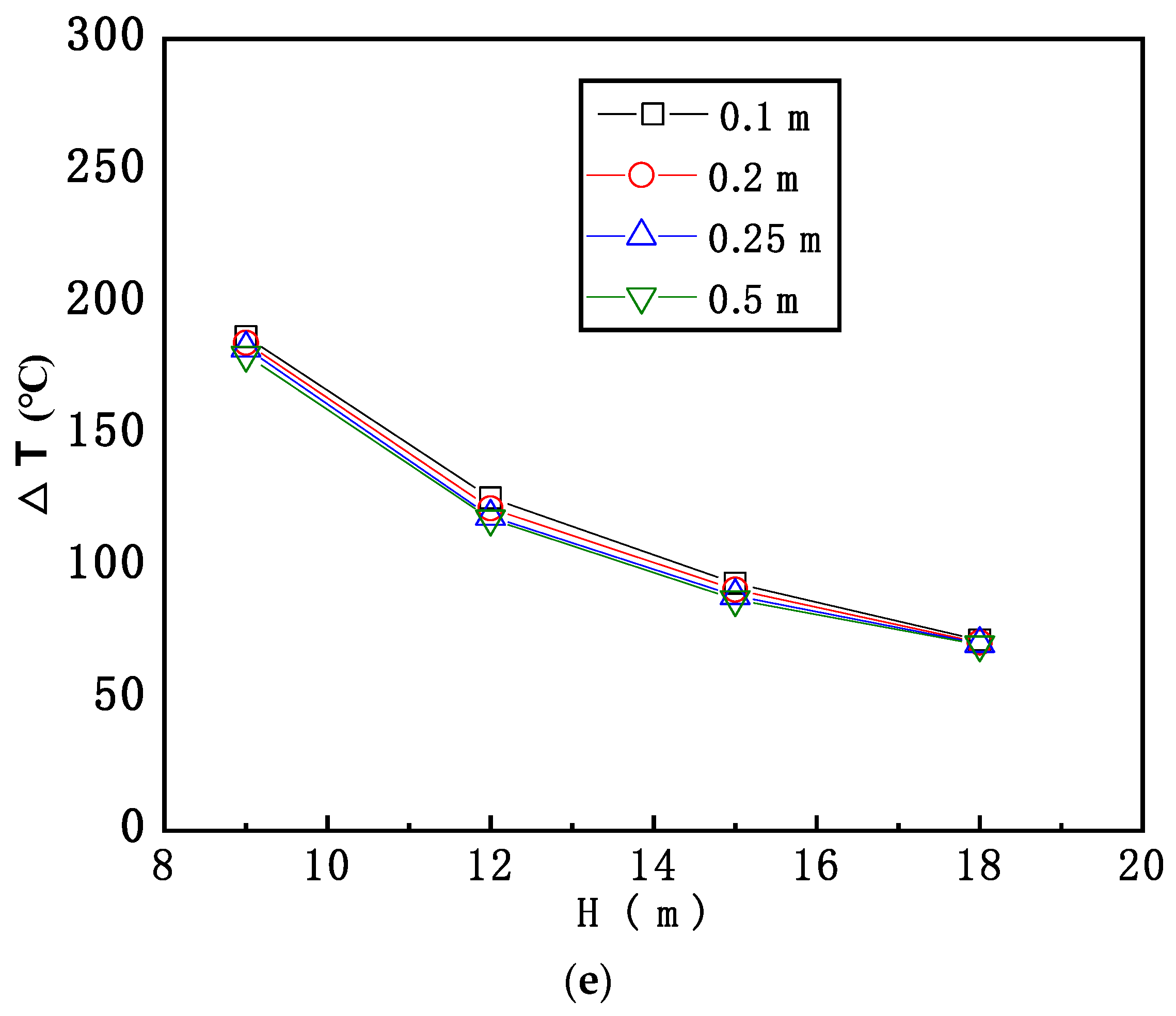
2.2. Grid Sensitivity
3. Results and Discussion
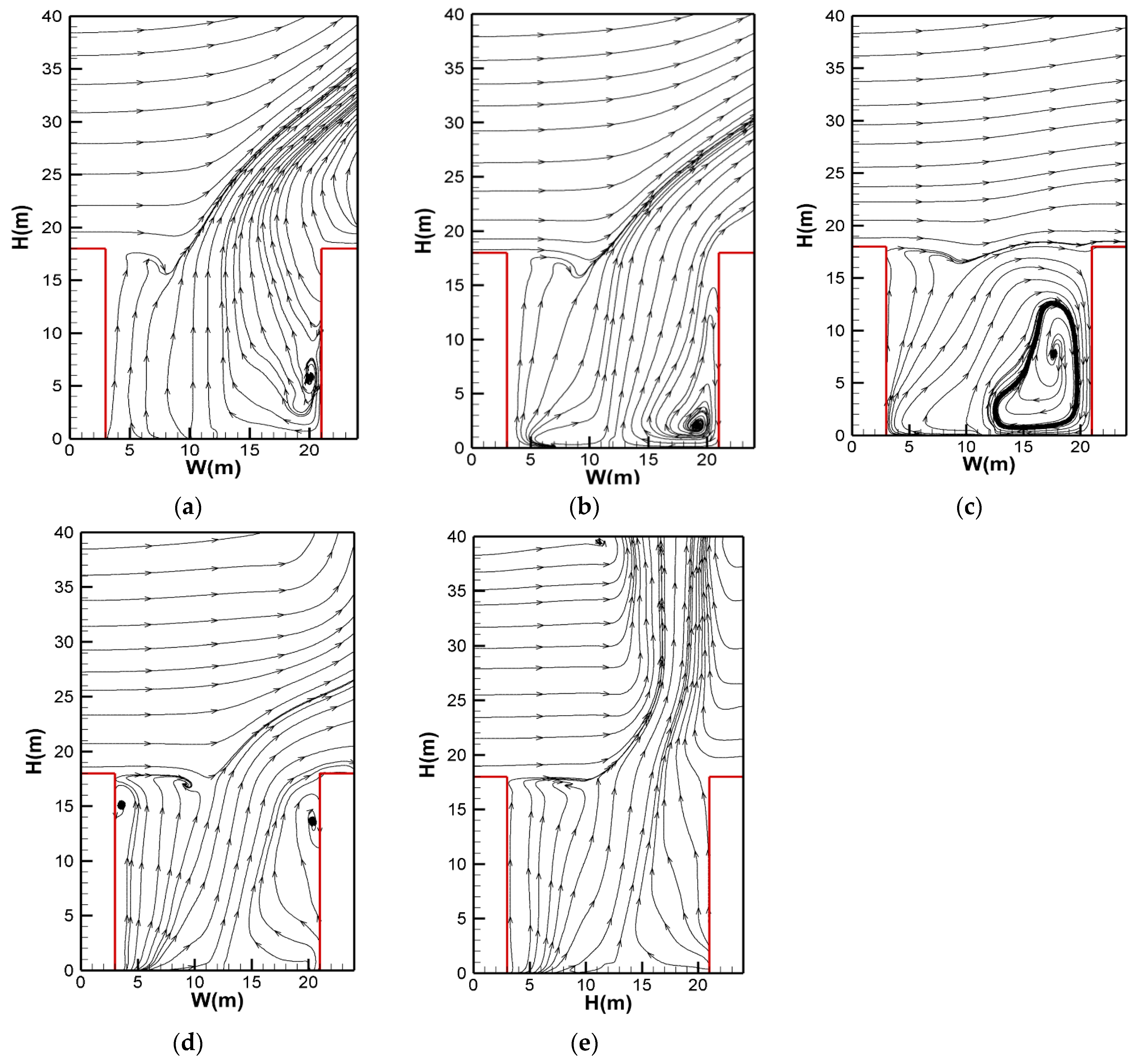
3.1. Smoke-Dispersion Behavior and Flow Field Inside the Street Canyon for Various Wind-Direction Conditions
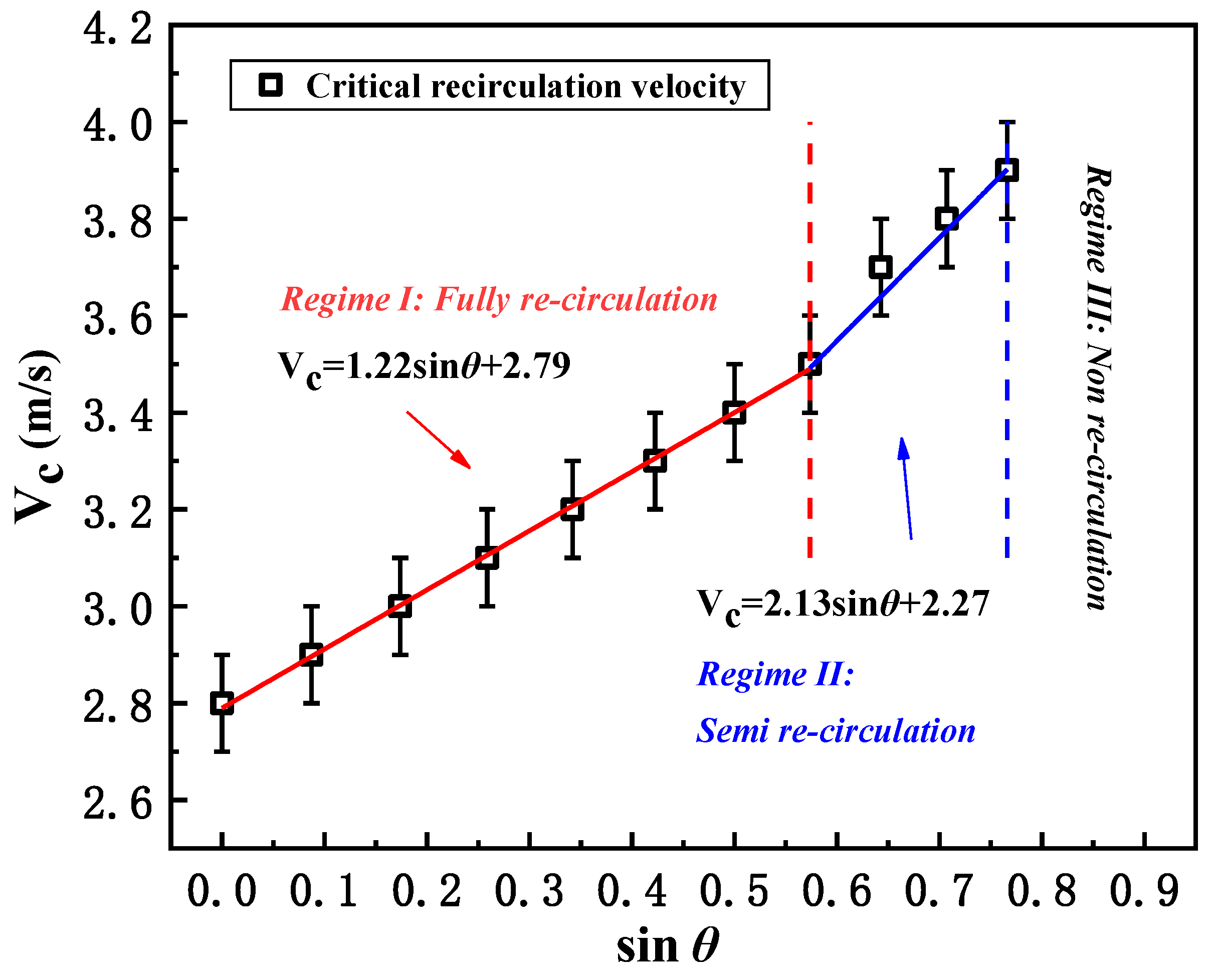
3.2. The Effect of Wind Direction on the Critical Recirculation Velocity of Smoke
3.3. A New Correlation between the Critical Froude Number and Recirculation Behavior
4. Conclusions
Author Contributions
Funding
Institutional Review Board Statement
Informed Consent Statement
Data Availability Statement
Conflicts of Interest
References
- Nicholson, S.E. A pollution model for street-level air. Atmos. Environ. 1975, 9, 19–31. [Google Scholar] [CrossRef] [PubMed]
- Sagrado, A.P.G.; van Beeck, J.; Rambaud, P.; Olivari, D. Numerical and experimental modelling of pollutant dispersion in a street canyon. J. Wind Eng. Ind. Aerodyn. 2002, 90, 321–339. [Google Scholar] [CrossRef]
- Nazridoust, K.; Ahmadi, G. Airflow and pollutant transport in street canyons. J. Wind Eng. Ind. Aerodyn. 2006, 94, 491–522. [Google Scholar] [CrossRef]
- Baik, J.J.; Kim, J.J. A numerical study of flow and pollutant dispersion characteristics in urban street canyons. J. Appl. Meteorol. 1999, 38, 1576–1589. [Google Scholar] [CrossRef]
- Depaul, F.T.; Sheih, C.M. Measurements of Wind Velocities in a Street Canyon. Atmos. Environ. 1986, 20, 455–459. [Google Scholar] [CrossRef]
- Solazzo, E.; Cai, X.M.; Vardoulakis, S. Modelling wind flow and vehicle-induced turbulence in urban streets. Atmos. Environ. 2008, 42, 4918–4931. [Google Scholar] [CrossRef]
- Park, S.J.; Kim, J.J.; Kim, M.J.; Park, R.J.; Cheong, H.B. Characteristics of flow and reactive pollutant dispersion in urban street canyons. Atmos. Environ. 2015, 108, 20–31. [Google Scholar] [CrossRef]
- Zhong, J.; Cai, X.M.; Bloss, W.J. Modelling the dispersion and transport of reactive pollutants in a deep urban street canyon: Using large-eddy simulation. Environ. Pollut. 2015, 200, 42–52. [Google Scholar] [CrossRef]
- Oke, T.R. Street Design and Urban Canopy Layer Climate. Energ. Build. 1988, 11, 103–113. [Google Scholar] [CrossRef]
- Tomson, M.; Kumar, P.; Barwise, Y.; Perez, P.; Forehead, H.; French, K.; Morawska, L.; Watts, J.F. Green infrastructure for air quality improvement in street canyons. Environ. Int. 2021, 146, 106288. [Google Scholar] [CrossRef]
- Huang, Y.-D.; Ren, S.-Q.; Xu, N.; Luo, Y.; Sin, C.H.; Cui, P.-Y. Impacts of specific street geometry on airflow and traffic pollutant dispersion inside a street canyon. Air Qual. Atmos. Health 2021, 15, 1–20. [Google Scholar] [CrossRef]
- Zhan, N.; Gao, Z.; Deng, Y. Diffusion of vehicle exhaust pollutants in typical street canyons. Int. J. Heat Technol. 2018, 36, 835–839. [Google Scholar] [CrossRef]
- Danilkin, E.A.; Starchenko, A.V.; Leschinsky, D.V. Research of the influence of the street canyon geometry on the turbulent flow structure. In Proceedings of the 26th International Symposium on Atmospheric and Ocean Optics, Atmospheric Physics, Moscow, Russia, 6–10 July 2020; Matvienko, G.G., Romanovskii, O.A., Eds.; SPIE: Bellingham, WA, USA; pp. 1586–1591. [Google Scholar]
- Wen, H.; Malki-Epshtein, L. A parametric study of the effect of roof height and morphology on air pollution dispersion in street canyons. J. Wind Eng. Ind. Aerodyn. 2018, 175, 328–341. [Google Scholar] [CrossRef]
- Li, L.; Li, Y.; Wu, Z.; Xu, P.; Peng, X.; Wang, H.; Fan, C. Window ejected thermal plume dispersion and recirculation behavior in urban street canyon with different building height ratios under wind. Case Stud. Therm. Eng. 2021, 27, 101220. [Google Scholar] [CrossRef]
- Cui, P.-Y.; Zhang, J.-H.; Wu, Y.-P.; Zhang, Y.; Zhou, J.-Z.; Luo, Y.; Huang, Y.-D. Wind-tunnel measurements and LES simulations of air pollutant dispersion caused by fire-induced buoyancy plume inside two parallel street canyons. Process. Saf. Environ. 2020, 140, 151–169. [Google Scholar] [CrossRef]
- Zhao, S.; Yang, H.; Li, C.; Obadi, I.; Wang, F.; Lei, W.; Xu, T.; Weng, M. Numerical investigation on fire-induced indoor and outdoor air pollutant dispersion in an idealized urban street canyon. Build. Simul. 2022, 15, 597–614. [Google Scholar] [CrossRef]
- Hu, L.H.; Huo, R.; Yang, D. Large eddy simulation of fire-induced buoyancy driven plume dispersion in an urban street canyon under perpendicular wind flow. J. Hazard. Mater. 2009, 166, 394–406. [Google Scholar] [CrossRef]
- Pesic, D.J.; Blagojevic, M.D.; Glisovic, S.M. The model of air pollution generated by fire chemical accident in an urban street canyon. Transp. Res. D Transp. Environ. 2011, 16, 321–326. [Google Scholar] [CrossRef]
- Pesic, D.J.; Blagojevic, M.D.J.; Zivkovic, N.V. Simulation of wind-driven dispersion of fire pollutants in a street canyon using FDS. Environ. Sci. Pollut. R 2014, 21, 1270–1284. [Google Scholar] [CrossRef]
- Hu, L.H.; Xu, Y.; Zhu, W.; Wu, L.; Tang, F.; Lu, K.H. Large eddy simulation of pollutant gas dispersion with buoyancy ejected from building into an urban street canyon. J. Hazard. Mater. 2011, 192, 940–948. [Google Scholar] [CrossRef]
- Hu, L.H.; Zhang, X.C.; Zhu, W.; Ning, Z.; Tang, F. A global relation of fire smoke re-circulation behaviour in urban street canyons. J. Civ. Eng. Manag. 2015, 21, 459–469. [Google Scholar] [CrossRef]
- Zhang, X.C.; Hu, L.H.; Tang, F.; Wang, Q. Large eddy simulation of fire smoke re-circulation in urban street canyons of different aspect ratios. Procedia Eng. 2013, 62, 1007–1014. [Google Scholar] [CrossRef]
- Wang, Z.L.; Lu, K.H.; Feng, L.; Tao, Y.; Wang, J.; Ding, Y.M.; Shi, C.L. Simulation on smoke re-circulation transition in an urban street canyon for different fire source locations with cross wind. Saf. Sci. 2020, 127, 104716. [Google Scholar] [CrossRef]
- Zhang, X.C.; Zhang, Z.J.; Su, G.K.; Tao, H.W.; Xu, W.H.; Hu, L.H. Buoyant wind-driven pollutant dispersion and recirculation behaviour in wedge-shaped roof urban street canyons. Environ. Sci. Pollut. R 2019, 26, 8289–8302. [Google Scholar] [CrossRef] [PubMed]
- Wang, Q.L.; Zhou, T.T.; Liu, Q.; He, P.X.; Tao, C.F.; Shi, Q. Numerical study of critical re-entrainment velocity of fire smoke within the street canyons with different building height ratios. Environ. Sci. Pollut. R 2019, 26, 23319–23327. [Google Scholar] [CrossRef] [PubMed]
- Soulhac, L.; Perkins, R.J.; Salizzoni, P. Flow in a street canyon for any external wind direction. Bound. Lay. Meteorol. 2008, 126, 365–388. [Google Scholar] [CrossRef]
- Soulhac, L.; Salizzoni, P. Dispersion in a street canyon for a wind direction parallel to the street axis. J. Wind Eng. Ind. Aerodyn. 2010, 98, 903–910. [Google Scholar] [CrossRef]
- Zhang, H.; Xu, T.T.; Wang, Y.X.; Zong, Y.Z.; Li, S.; Tang, H.J. Study on the influence of meteorological conditions and the street side buildings on the pollutant dispersion in the street canyon. Build. Simul. 2016, 9, 717–727. [Google Scholar] [CrossRef]
- Kumar, P.; Fennell, P.; Britter, R. Effect of wind direction and speed on the dispersion of nucleation and accumulation mode particles in an urban street canyon. Sci. Total Environ. 2008, 402, 82–94. [Google Scholar] [CrossRef]
- Huang, Y.D.; Hou, R.W.; Liu, Z.Y.; Song, Y.; Cui, P.Y.; Kim, C.N. Effects of Wind Direction on the Airflow and Pollutant Dispersion inside a Long Street Canyon. Aerosol. Air Qual. Res. 2019, 19, 1152–1171. [Google Scholar] [CrossRef]
- Tominaga, Y.; Stathopoulos, T. CFD modeling of pollution dispersion in a street canyon: Comparison between LES and RANS. J. Wind Eng. Ind. Aerodyn. 2011, 99, 340–348. [Google Scholar] [CrossRef]
- Salim, S.M.; Buccolieri, R.; Chan, A.; Di Sabatino, S. Numerical simulation of atmospheric pollutant dispersion in an urban street canyon: Comparison between RANS and LES. J. Wind Eng. Ind. Aerodyn. 2011, 99, 103–113. [Google Scholar] [CrossRef]
- Baker, J.; Walker, H.L.; Cai, X.M. A study of the dispersion and transport of reactive pollutants in and above street canyons-a large eddy simulation. Atmos. Environ. 2004, 38, 6883–6892. [Google Scholar] [CrossRef]
- Chang, C.H. Computational fluid dynamics simulation of concentration distributions from a point source in the urban street canyons. J. Aerosp. Eng. 2006, 19, 80–86. [Google Scholar] [CrossRef]
- Salizzoni, P.; Grosjean, N.; Mejean, P.; Perkins, R.J.; Soulhac, L.; Vanliefferinge, R. Wind tunnel study of the exchange between a street canyon and the external flow. Air Pollut. Model. Appl. XVII 2007, 17, 430–437. [Google Scholar] [CrossRef]
- Tao, C.F.; Wang, K.; Liu, Q.; He, P.X. A simulation investigation of fire smoke behavior above urban street canyon. Procedia Eng. 2018, 211, 681–688. [Google Scholar] [CrossRef]
- McGrattan, K.; Hostikka, S.; McDermott, R.; Floyd, J.; Weinschenk, C.; Overholt, K. Fire Dynamics Simulator Technical Reference Guide Volume 1: Mathematical Model; National Institute of Standards and Technology: Gaithersburg, MD, USA, 2013; Volume 1018, p. 175. [Google Scholar] [CrossRef]


| θ (°) | Wind Velocity (m/s) | |||||
|---|---|---|---|---|---|---|
| 0 | 2.6 | 2.7 | 2.8 | 2.9 | 3.0 | / |
| 5 | 2.6 | 2.7 | 2.8 | 2.9 | 3.0 | 3.1 |
| 10 | 2.8 | 2.9 | 3.0 | 3.1 | 3.2 | 3.3 |
| 15 | 2.9 | 3.0 | 3.1 | 3.2 | 3.3 | / |
| 20 | 3.0 | 3.1 | 3.2 | 3.3 | 3.4 | / |
| 25 | 3.1 | 3.2 | 3.3 | 3.4 | 3.5 | / |
| 30 | 3.2 | 3.3 | 3.4 | 3.5 | 3.6 | / |
| 35 | 3.3 | 3.4 | 3.5 | 3.6 | 3.7 | / |
| 40 | 3.4 | 3.5 | 3.6 | 3.7 | 3.8 | 3.9 |
| 45 | 3.5 | 3.6 | 3.7 | 3.8 | 3.9 | 4.0 |
| 50 | 3.6 | 3.7 | 3.8 | 3.9 | 4.0 | 4.1 |
| 55 | 3.7 | 3.8 | 3.9 | 4.0 | 6.0 | 10.0 |
| 60 | 4.0 | 6.0 | 8.0 | 10.0 | / | / |
| 65 | 4.0 | 6.0 | 8.0 | 10.0 | / | / |
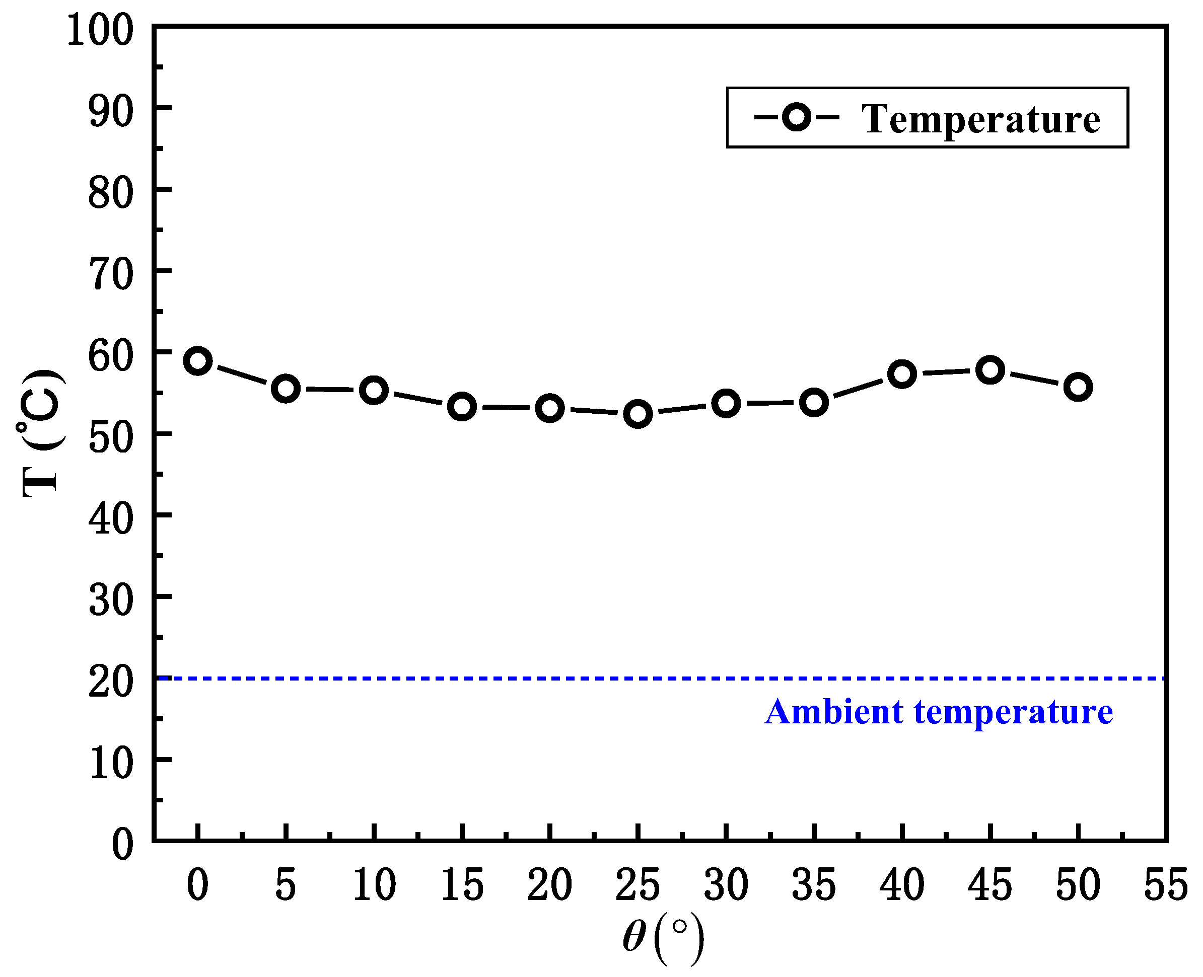
| θ (°) | VC (m/s) | ∆Tz (°C) | Fr |
|---|---|---|---|
| 0 | 2.8 | 38.9 | 0.579 |
| 5 | 2.9 | 35.5 | 0.627 |
| 10 | 3 | 35.3 | 0.651 |
| 15 | 3.1 | 33.3 | 0.692 |
| 20 | 3.2 | 33.1 | 0.717 |
| 25 | 3.3 | 32.4 | 0.747 |
| 30 | 3.4 | 33.7 | 0.755 |
| 35 | 3.5 | 33.8 | 0.776 |
| 40 | 3.7 | 37.3 | 0.781 |
| 45 | 3.8 | 37.8 | 0.797 |
| 50 | 3.9 | 35.7 | 0.841 |
Disclaimer/Publisher’s Note: The statements, opinions and data contained in all publications are solely those of the individual author(s) and contributor(s) and not of MDPI and/or the editor(s). MDPI and/or the editor(s) disclaim responsibility for any injury to people or property resulting from any ideas, methods, instructions or products referred to in the content. |
© 2023 by the authors. Licensee MDPI, Basel, Switzerland. This article is an open access article distributed under the terms and conditions of the Creative Commons Attribution (CC BY) license (https://creativecommons.org/licenses/by/4.0/).
Share and Cite
Lu, K.; Xiang, Y.; Yu, S.; Wang, J.; Mao, S. Investigation of the Wind-Direction Effect on Buoyancy-Driven Fire Smoke Dispersion in an Urban Street Canyon. Int. J. Environ. Res. Public Health 2023, 20, 2568. https://doi.org/10.3390/ijerph20032568
Lu K, Xiang Y, Yu S, Wang J, Mao S. Investigation of the Wind-Direction Effect on Buoyancy-Driven Fire Smoke Dispersion in an Urban Street Canyon. International Journal of Environmental Research and Public Health. 2023; 20(3):2568. https://doi.org/10.3390/ijerph20032568
Chicago/Turabian StyleLu, Kaihua, Yanqing Xiang, Songyang Yu, Jie Wang, and Shaohua Mao. 2023. "Investigation of the Wind-Direction Effect on Buoyancy-Driven Fire Smoke Dispersion in an Urban Street Canyon" International Journal of Environmental Research and Public Health 20, no. 3: 2568. https://doi.org/10.3390/ijerph20032568
APA StyleLu, K., Xiang, Y., Yu, S., Wang, J., & Mao, S. (2023). Investigation of the Wind-Direction Effect on Buoyancy-Driven Fire Smoke Dispersion in an Urban Street Canyon. International Journal of Environmental Research and Public Health, 20(3), 2568. https://doi.org/10.3390/ijerph20032568