
The Influence of Low-Energy Impact Loads on the Properties of the Sandwich Composite with a Foam Core

 , , , and
Abstract
1. Introduction
- -
- Homogeneous structures—e.g., balsa,
- -
- Network (cellular) structures—e.g., honeycomb structure,
- -
- Heterogeneous structures—e.g., cellular foams.
- -
- BVID—barely visible impact damage,
- -
- VID—visible impact damage.
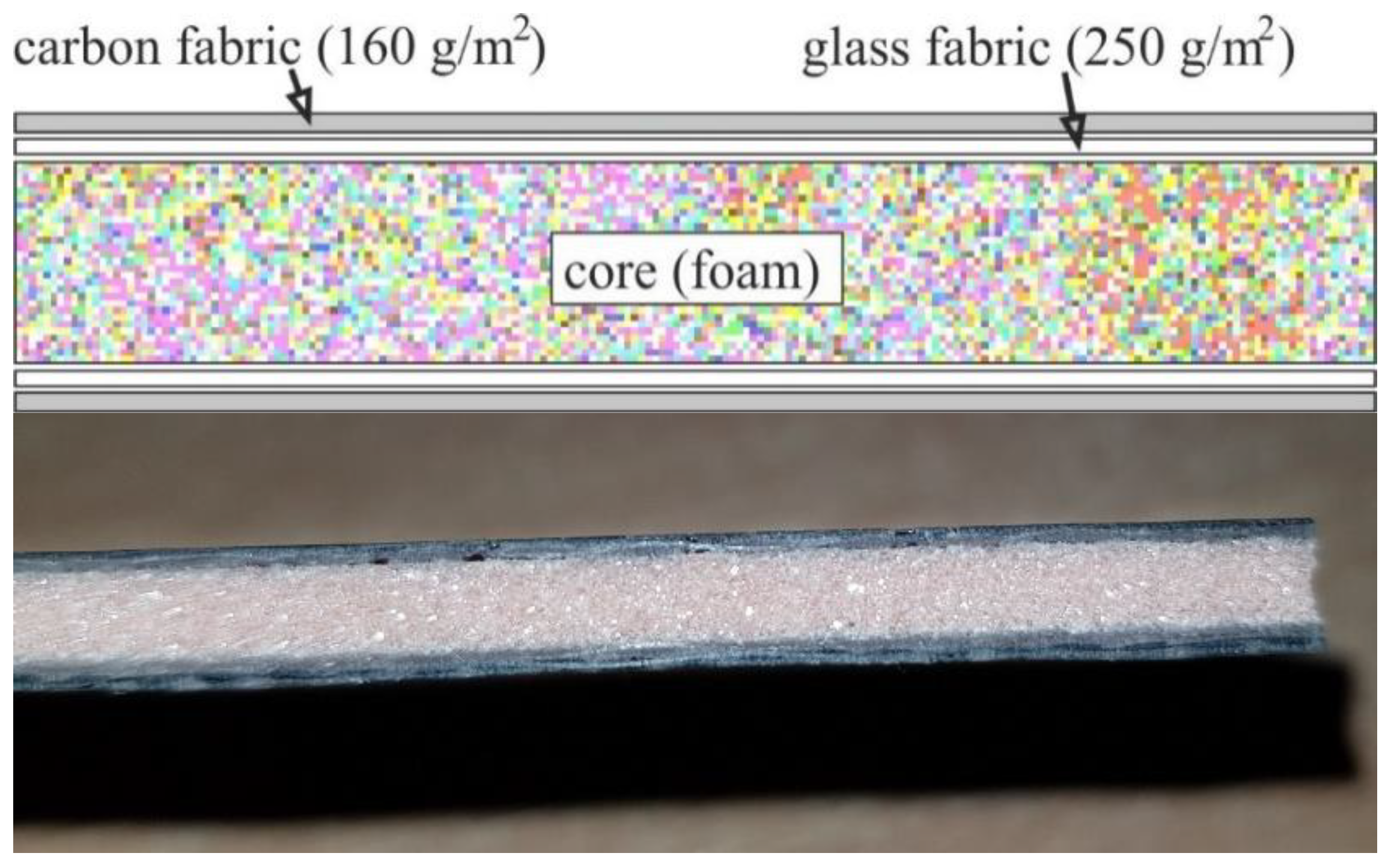
2. Tested Composites
3. Experimental Research
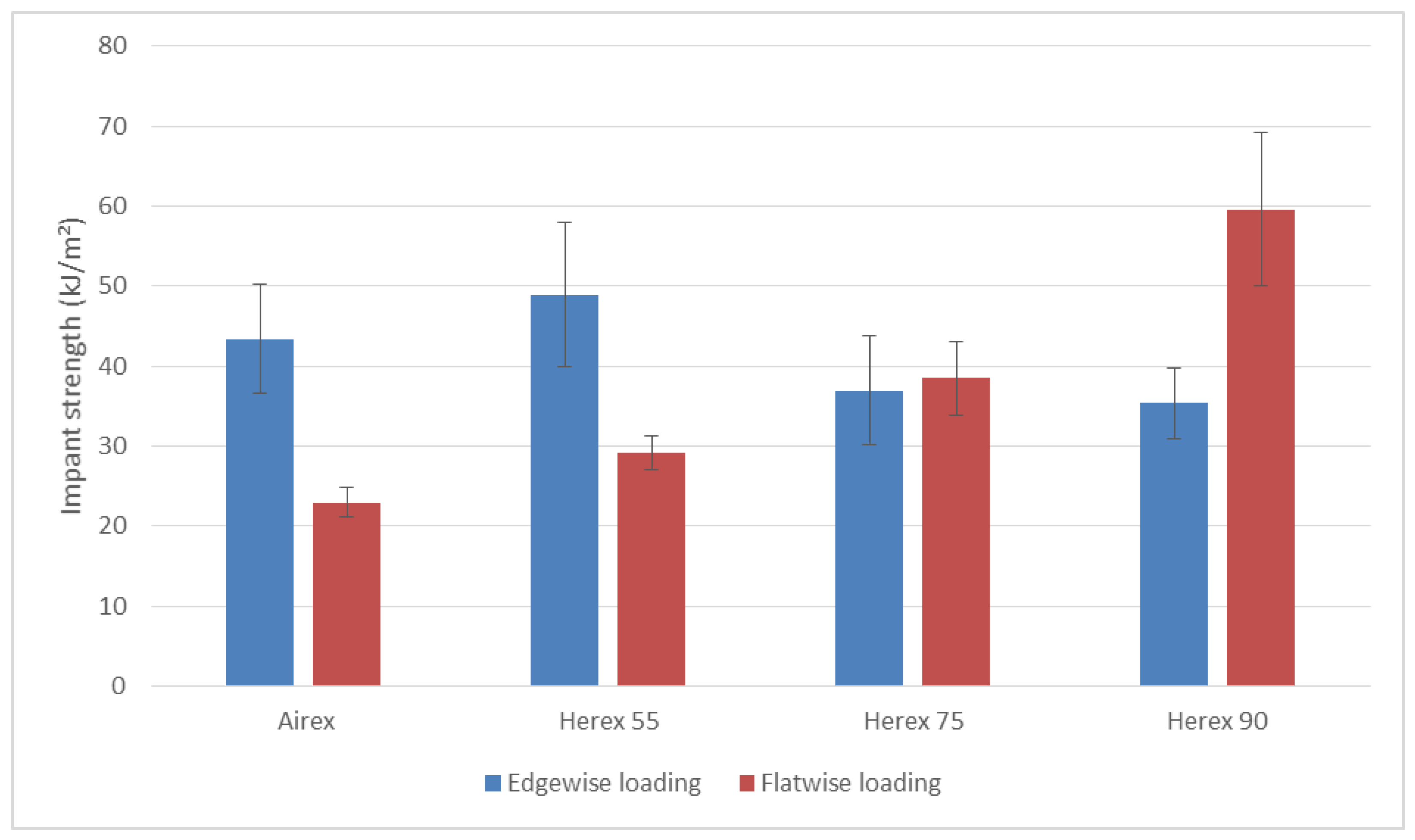
3.1. Impact Strength Testing
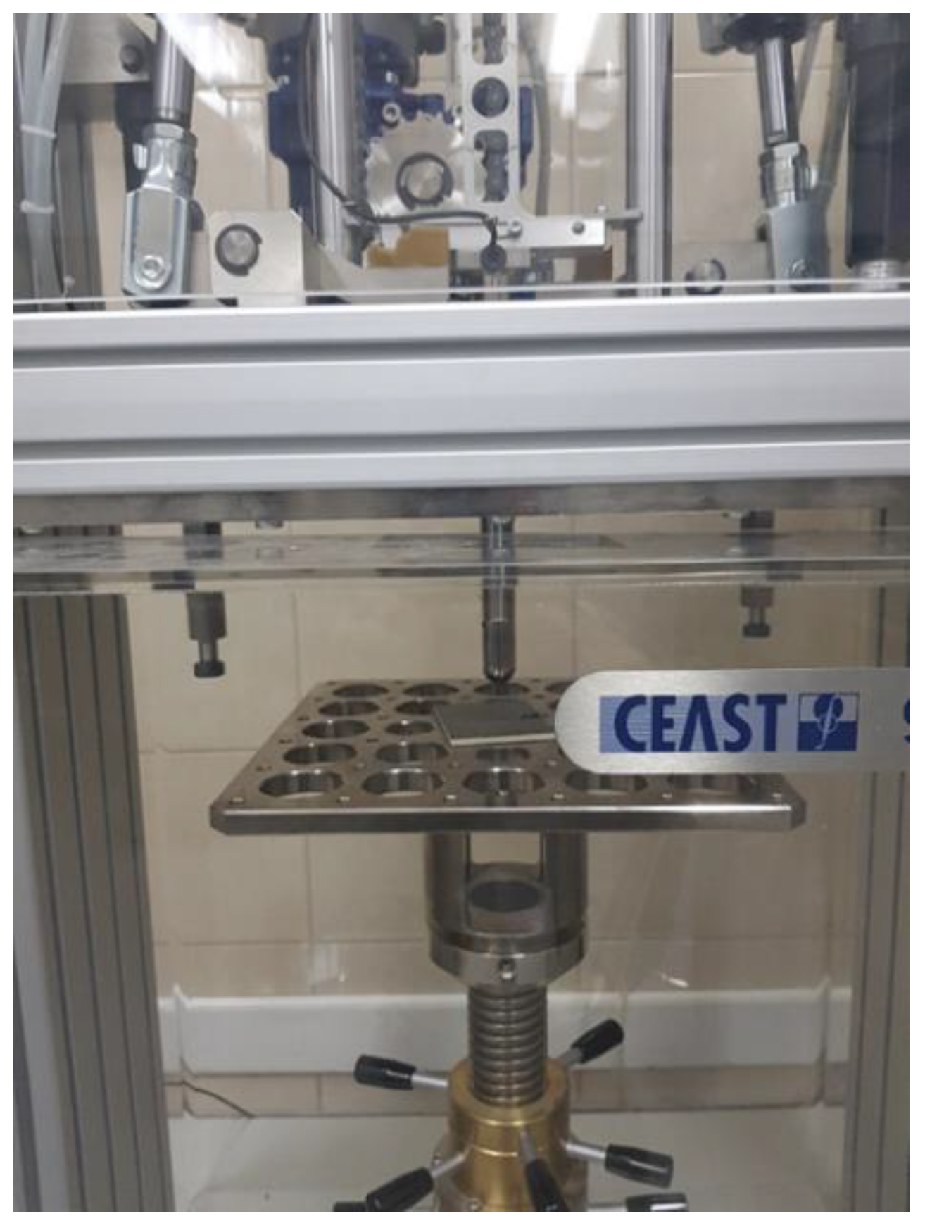
3.2. Resistance to Puncture Testing
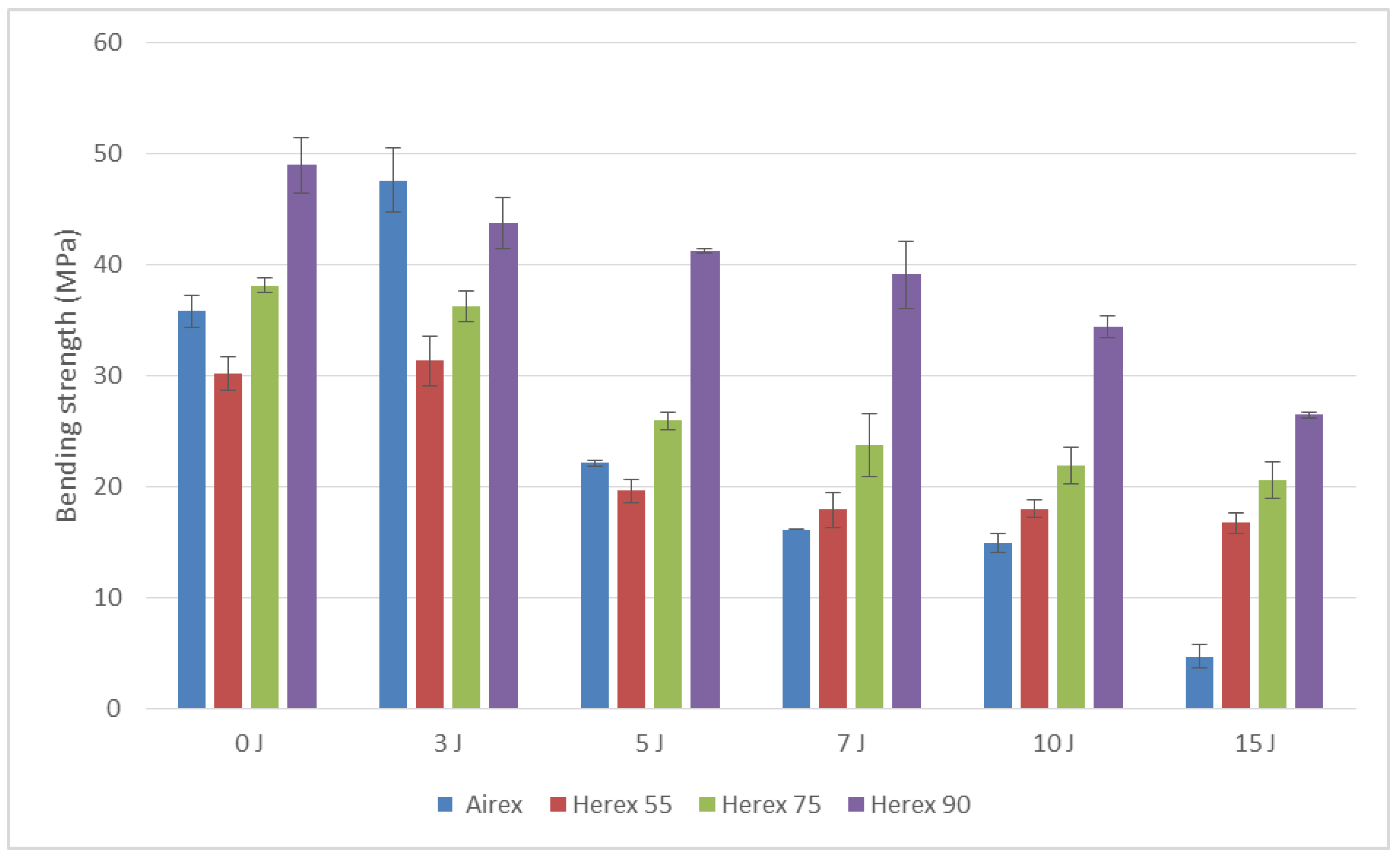
3.3. Bending Strength Testing
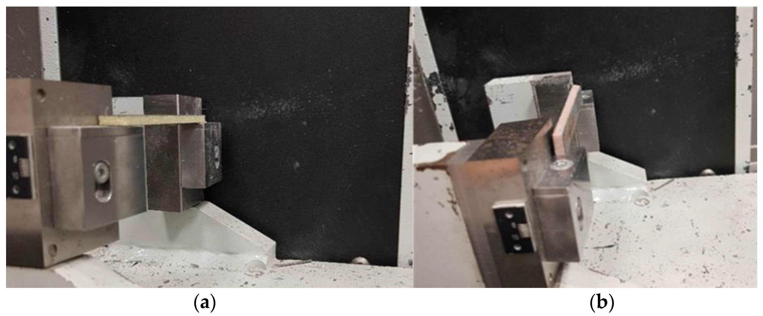
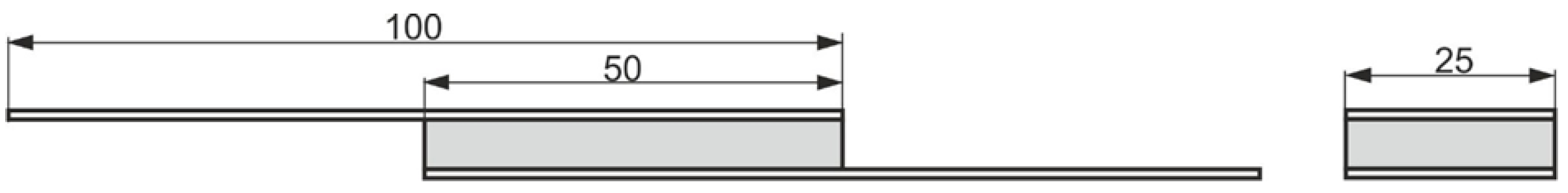
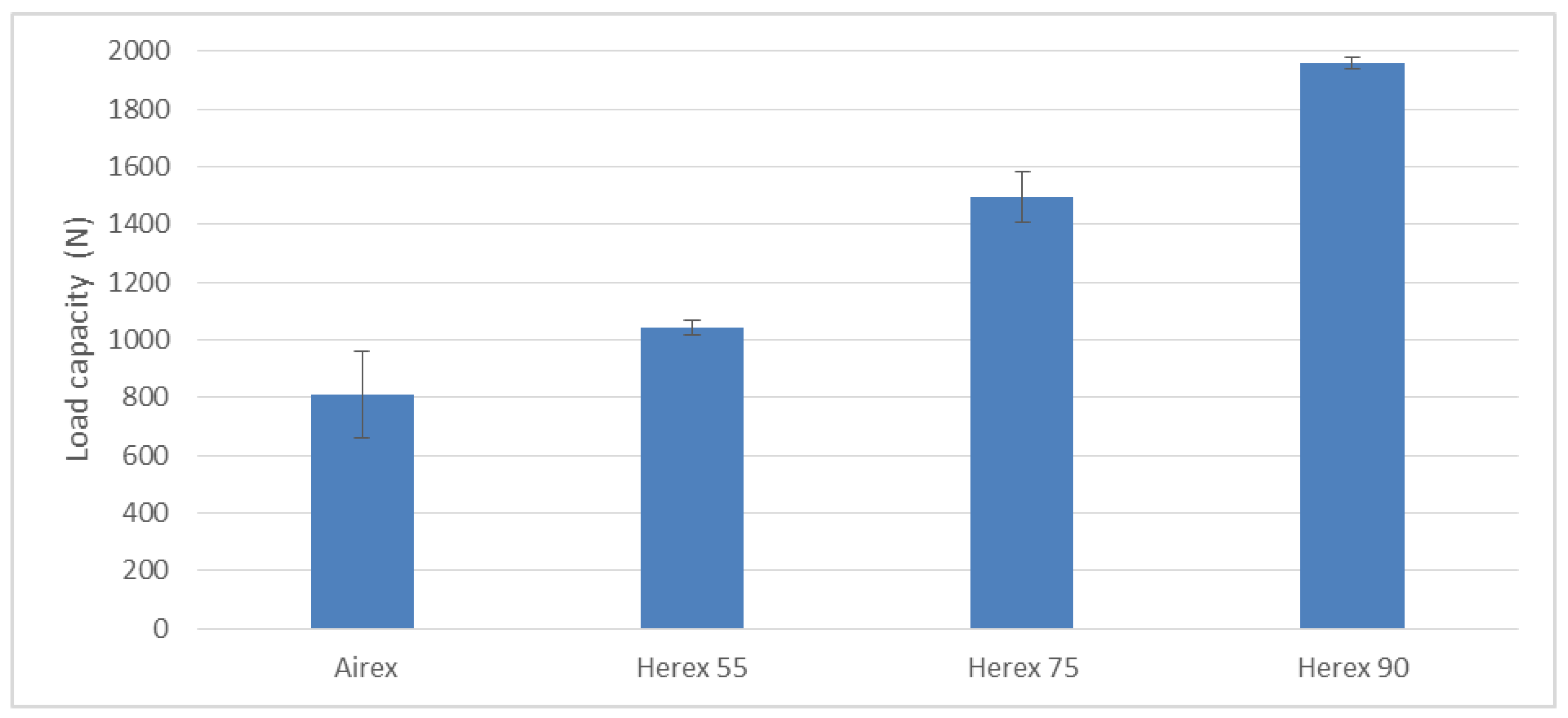
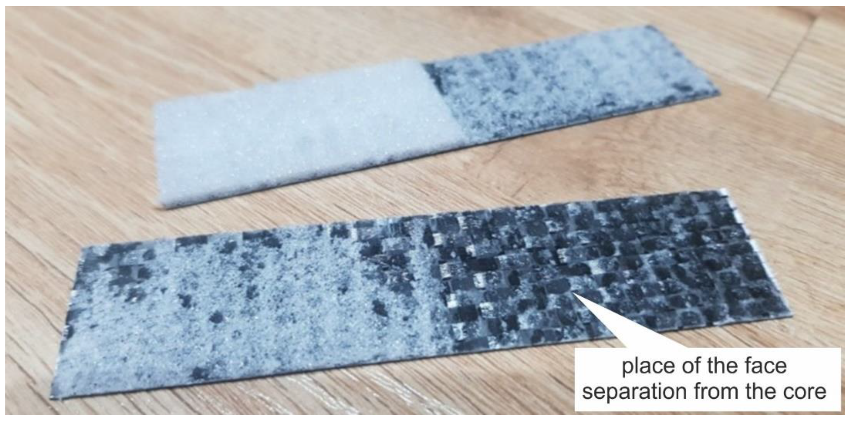
3.4. Shear Strength Testing of Cores
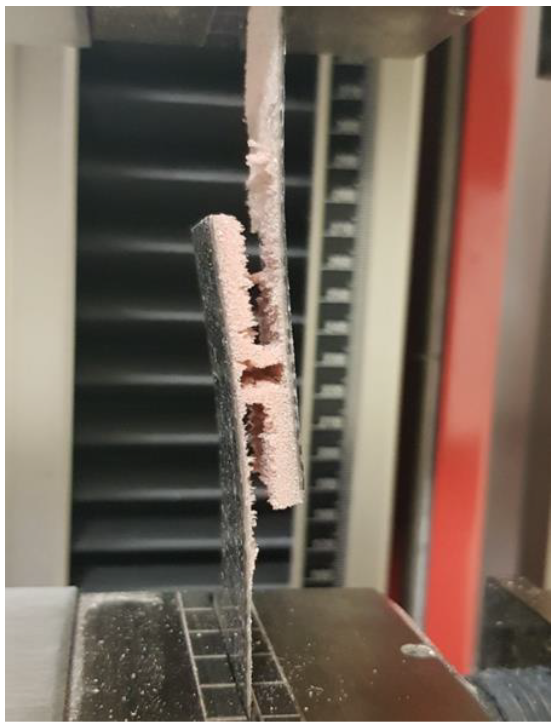
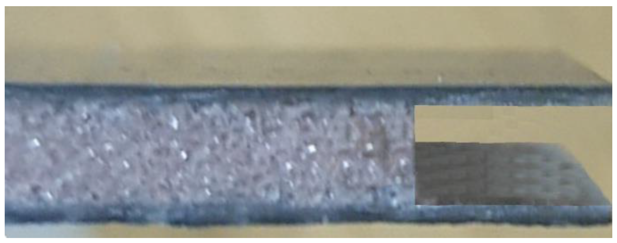
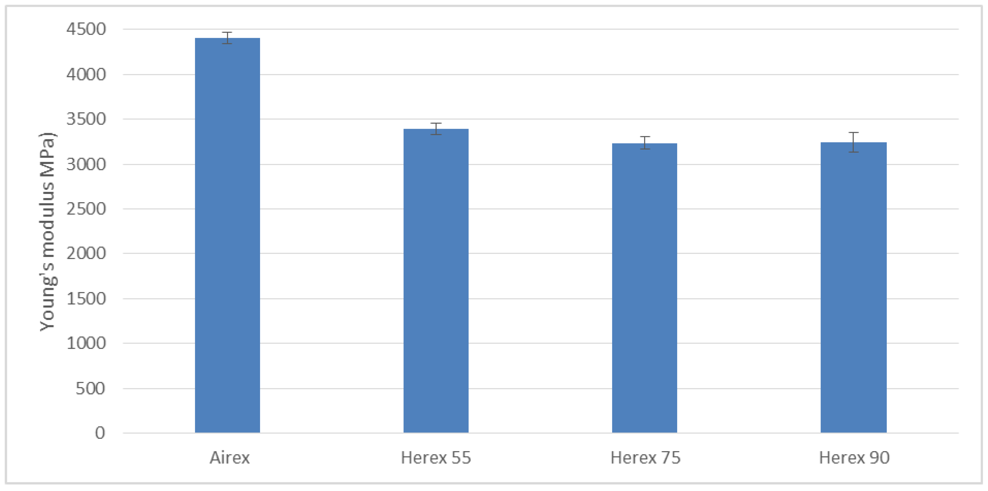
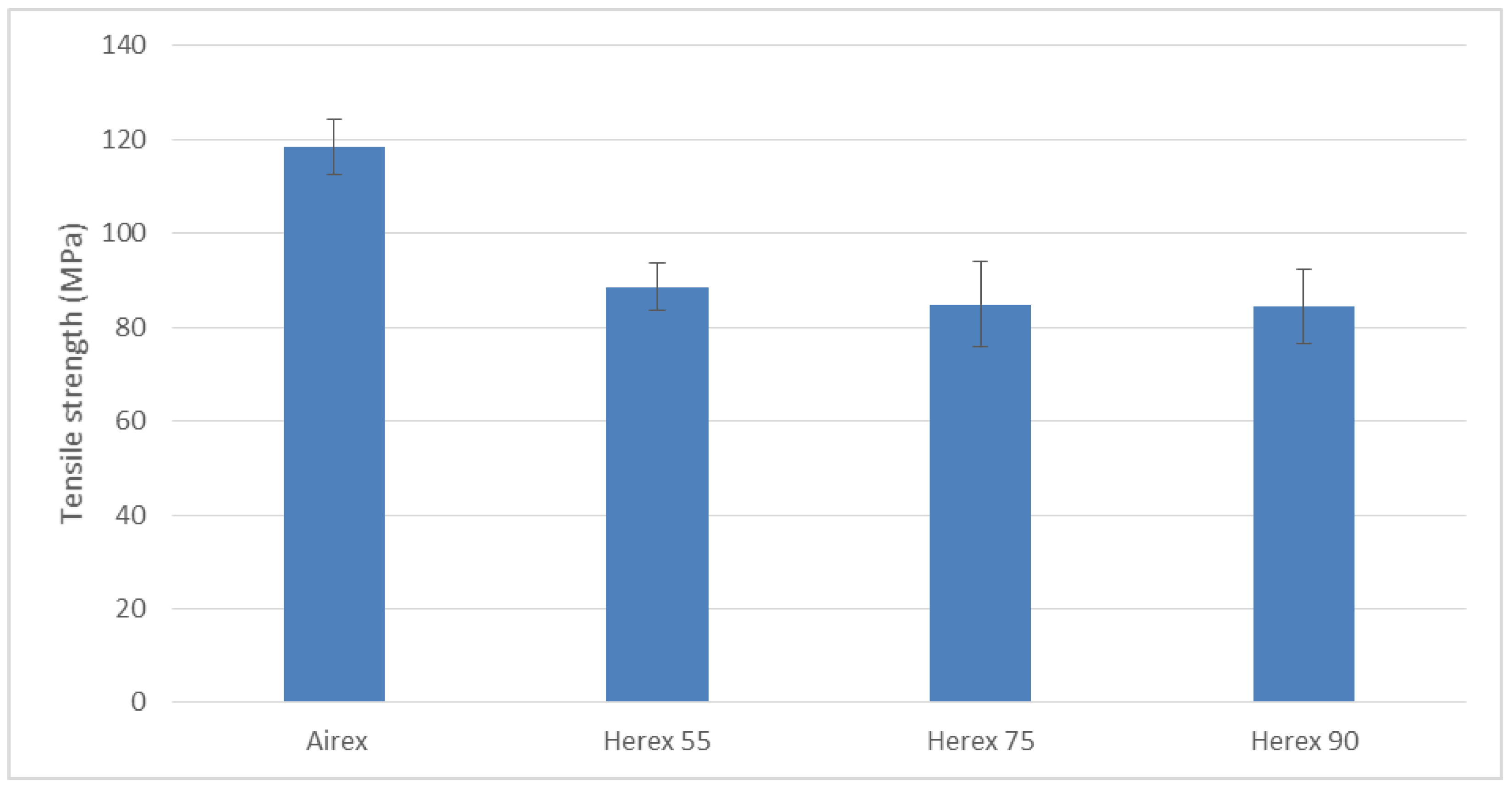
3.5. Static Tensile Test
4. Conclusions
Author Contributions
Funding
Institutional Review Board Statement
Informed Consent Statement
Data Availability Statement
Conflicts of Interest
References
- Szczepaniak, R.; Komorek, A.; Przybylek, P.; Krzyzak, A.; Roskowicz, M.; Godzimirski, J.; Pinkiewicz, E.; Jaszczak, W.; Kosicka, E. Research into mechanical properties of an ablative composite on a polymer matrix base with aerogel particles. Compos. Struct. 2022, 280, 114855. [Google Scholar] [CrossRef]
- Xiao, B.; Wang, W.; Zhang, X.; Long, G.; Fan, J.; Chen, H.; Deng, L. A novel fractal solution for permeability and Kozeny-Carman constant of fibrous porous media made up of solid particles and porous fibers. Powder Technol. 2019, 349, 92–98. [Google Scholar] [CrossRef]
- Komorek, A.; Komorek, Z.; Krzyzak, A.; Przybylek, P.; Szczepaniak, R. Impact of Frequency of Load Changes in Fatigue Tests on the Temperature of the Modified Polymer. Int. J. Thermophys. 2017, 38, 128. [Google Scholar] [CrossRef]
- Bank, L.C. Composites for Construction: Structural Design with FRP Materials; Wiley: Hoboken, NJ, USA, 2006. [Google Scholar]
- Soutis, C. Fibre reinforced composites in aircraft construction. Prog. Aerosp. Sci. 2005, 41, 143–151. [Google Scholar] [CrossRef]
- Beck, A.J.; Hodzic, A.; Soutis, C.; Wilson, C. IOP Conference Series: Materials Science and Engineering. In Proceedings of the Trends in Aerospace Manufacturing International Conference, Sheffield, UK, 9–10 September 2009; IOP Publishing Ltd.: Bristol, UK, 2011; p. 26. [Google Scholar]
- Królikowski, W. Polimerowe Kompozyty Konstrukcyjne; Wydawnictwo Naukowe PWN: Warszawa, Poland, 2012. [Google Scholar]
- Vasiliev, V.V.; Morozov, E.V. Advanced Mechanics of Composite Materials and Structures; Elsevier: Amsterdam, The Netherlands, 2018. [Google Scholar]
- Hou, S.; Li, Q.; Long, S.; Yang, X.; Li, W. Crashworthiness design for foam filled thin-wall structures. Mater. Des. 2009, 30, 2024–2032. [Google Scholar] [CrossRef]
- Li, T.; Wang, L. Bending behavior of sandwich composite structures with tunable 3D-printed core materials. Compos. Struct. 2017, 175, 46–57. [Google Scholar] [CrossRef]
- Ullah, I.; Elambasseril, J.; Brandt, M.; Feih, S. Performance of bio-inspired Kagome truss core structures under compression. Compos. Struct. 2014, 118, 294–302. [Google Scholar] [CrossRef]
- Castanie, B.; Bouvet, C.; Ginot, M. Review of composite sandwich structure in aeronautic applications. Compos. Part C 2020, 1, 100004. [Google Scholar] [CrossRef]
- Zenkert, D. An Introduction to Sandwich Construction; Engineering Materials Advisory Service: London, UK, 1995. [Google Scholar]
- Plantema, F.J. Sandwich Construction; John Wiley & Sons: New York, NY, USA, 1966. [Google Scholar]
- Hegde, S.; Hojjati, M. Effect of core and facesheet thickness on mechanical property of composite sandwich structures subjected to thermal fatigue. Int. J. Fatigue 2019, 127, 16–24. [Google Scholar] [CrossRef]
- Kaboglu, C.; Yu, L.; Mohagheghian, I.; Blackman, B.R.K.; Kinloch, A.J.; Dear, J.P. Effects of the core density on the quasi-static flexural and ballistic performance of fibre-composite skin/foam core sandwich structures. J. Mater. Sci. 2018, 53, 16393–16414. [Google Scholar] [CrossRef]
- Yan, C.; Song, X. Effects of foam core density and face-sheet thickness on the mechanical properties of aluminum foam sandwich. Steel Compos. Struct. 2016, 21, 1145–1156. [Google Scholar] [CrossRef]
- Contreiras, T.R.M.; Pragana, J.P.M.; Bragança, I.M.F.; Silva, C.M.A.; Alves, L.M.; Martins, P.A.F. Joining by forming of lightweight sandwich composite panels. Procedia Manuf. 2019, 29, 288–295. [Google Scholar] [CrossRef]
- Palkowski, H.; Sokolova, O.A.; Carradò, A. Chapter: Sandwich Materials. In Encyclopedia of Automotive Engineering; Crolla, D., Foster, D.E., Kobayashi, T., Vaughan, N., Eds.; John Wiley & Sons, Ltd.: Chichester, UK, 2015. [Google Scholar]
- Kim, B.J.; Lee, D.G. Characteristics of joining inserts for composite sandwich panels. Compos. Struct. 2008, 86, 55–60. [Google Scholar] [CrossRef]
- Juntikka, R.; Hallstrom, S. Shear Characterization of Sandwich Core Materials Using Four-point Bending. J. Sandw. Struct. Mater. 2007, 9, 67–94. [Google Scholar] [CrossRef]
- Święch, Ł.; Kołodziejczyk, R.; Stącel, N. Experimental Analysis of Perimeter Shear Strength of Composite Sandwich Structures. Materials 2020, 14, 12. [Google Scholar] [CrossRef]
- Bezazi, A.; El Mahi, A.; Berthelot, J.M.; Bezzazi, B. Experimental analysis of behavior and damage of sandwich composite materials in three-point bending. Part 1. Static tests and stiffness degradation at failure studies. Strength Mater. 2007, 39, 170–177. [Google Scholar] [CrossRef][Green Version]
- Galletti, G.G.; Vinquist, C.; Es-Said, O.S. Theoretical design and analysis of a honeycomb panel sandwich structure loaded in pure bending. Eng. Fail. Anal. 2008, 15, 555–562. [Google Scholar] [CrossRef]
- Jones, J.G. Marine Applications of Advanced Fibre-Reinforced Composites; Elsevier: Amsterdam, The Netherlands, 2016. [Google Scholar]
- Baker, A.A.; Scott, M.L. Composite Materials for Aircraft Structures, 3rd ed.; AIAA/American Institute of Aeronautics and Astronautics: Reston, VA, USA, 2016. [Google Scholar]
- Hagnell, M.K.; Kumaraswamy, S.; Nyman, T.; Åkermo, M. From aviation to automotive—A study on material selection and its implication on cost and weight efficient structural composite and sandwich designs. Heliyon 2020, 6, e03716. [Google Scholar] [CrossRef]
- Batra, R.C.; Gopinath, G.; Zheng, J.Q. Damage and failure in low energy impact of fiber-reinforced polymeric composite laminates. Compos. Struct. 2012, 94, 540–547. [Google Scholar] [CrossRef]
- Perillo, G.; Jørgensen, J.K. Numerical/Experimental Study of the Impact and Compression after Impact on GFRP Composite for Wind/Marine Applications. Procedia Eng. 2016, 167, 129–137. [Google Scholar] [CrossRef]
- Komorek, A.; Przybyłek, P. Examination of the influence of cross-impact load on bend strength properties of composite materials, used in aviation. Eksploat. Niezawodn. 2012, 14, 265–269. [Google Scholar]
- Lingling, L.; Yabo, W.; Jianquan, B.; Cheng, L.; Hongwei, S.; Chenguang, H. Internal Damage Identification of Sandwich Panels with Truss Core Through Dynamic Properties and Deep Learning. Front. Mater. 2020, 7. [Google Scholar] [CrossRef]
- He, Y.Z.; Tian, G.Y.; Pan, M.C.; Chen, D.X. Non-destructive test of low-energy impact in CFRP laminates and interior defects in honeycomb sandwich using scanning pulsed eddy current. Compos. B Eng. 2014, 59, 196–203. [Google Scholar] [CrossRef]
- Weitzenböck, J.R.; Echtermeyer, A.T.; Artiga-Dubois, F.; Parmar, M. Nondestructive Inspection and Evaluation Methods for Sandwich Panels. In Proceedings of the 4th International Conference on Sandwich Construction, Stockholm, Sweden, 9–11 June 1998. [Google Scholar]
- Borum, K.K.; Berggreen, C. Examination of Sandwich Materials Using Air-Coupled Ultrasonics. In Proceedings of the 16th World Conference on Destructive Testing, Montréal, QC, Canada, 31 August–3 September 2004. [Google Scholar]
- Meo, M.; Zumpano, G.; Piggott, M.; Marengo, G. Impact identification on a sandwich plate from wave propagation responses. Compos. Struct. 2005, 71, 302–306. [Google Scholar] [CrossRef]
- Katunin, A. Vibration-based spatial damage identification in honeycomb-core sandwich composite structures using wavelet analysis. Compos. Struct. 2014, 118, 385–391. [Google Scholar]
- Safri, S.N.A.; Sultan, M.T.H.; Yidris, N.; Mustapha, F. Low Velocity and High Velocity Impact Test on Composite Materials—A review. Int. J. Eng. Sci. 2014, 3, 50–60. [Google Scholar]
- Neveu, F.; Castanié, B.; Olivier, P. The GAP methodology: A new way to design composite structure Mater. Des. 2019, 172, 107755. [Google Scholar] [CrossRef]
- Razali, N.; Sultan, M.T.H.; Mustapha, F.; Yidris, N.; Ishak, M.R. Impact Damage on Composite Structures—A Review. Int. J. Eng. Sci. 2014, 3, 8–20. [Google Scholar]
- Schubel, P.M.; Luo, I.J.; Daniel, I.M. Impact and post impact behavior of composite sandwich panels. Compos. A Appl. Sci. Manuf. 2007, 38, 1051–1057. [Google Scholar] [CrossRef]
- Xia, F.; Wu, X. Work on low-velocity impact properties of foam sandwich composites with various face sheets. J. Reinf. Plast. Compos. 2010, 29, 1045–1054. [Google Scholar]
- Feng, D.; Aymerich, F. Damage prediction in composite sandwich panels subjected to low-velocity impact. Compos. A Appl. Sci. Manuf. 2013, 52, 12–22. [Google Scholar] [CrossRef]
- Long, S.; Yao, X.; Wang, H.; Zhang, X. Failure analysis and modeling of foam sandwich laminates under impact loading. Compos. Struct. 2018, 197, 10–20. [Google Scholar] [CrossRef]
- Muc, A.; Nogowczyk, R. Failure modes of sandwich structures with composite faces. Kompozyty 2005, 5, 31–35. [Google Scholar]
- Shin, K.B.; Lee, J.Y.; Cho, S.H. An experimental study of low-velocity impact responses of sandwich panels for Korean low floor bus. Compos. Struct. 2008, 84, 228–240. [Google Scholar] [CrossRef]
- Salami, S.J.; Sadighi, M.; Shakeri, M.; Moeinfar, M. An Investigation on Low Velocity Impact Response of Multilayer Sandwich Composite Structures. Sci. World J. 2013, 2013, 175090. [Google Scholar] [CrossRef]
- Zhu, Y.; Sun, Y. Low-velocity impact response of multilayer foam core sandwich panels with composite face sheets. Int. J. Mech. Sci. 2021, 209, 106704. [Google Scholar] [CrossRef]
- Huo, X.; Liu, H.; Luo, Q.; Sun, G.; Li, Q. State Key on low-velocity impact response of foam-core sandwich panels. Int. J. Mech. Sci. 2020, 181, 105681. [Google Scholar] [CrossRef]
- Srivastava, V.K. Impact Behaviour of Sandwich GFRP-Foam-GFRP Composites. Int. J. Compos. Mater. 2012, 2, 63–66. [Google Scholar] [CrossRef]
- Liu, Q.; Ge, Z.; Song, W. Research Based on Patent Analysis about the Present Status and Development Trends of Unmanned Aerial Vehicle in China. Open J. Soc. Sci. 2016, 4, 172–181. [Google Scholar] [CrossRef][Green Version]
- Jo, D.; Kwon, Y. Development of Rescue Material Transport UAV (Unmanned Aerial Vehicle). World J. Eng. Technol. 2017, 5, 720–729. [Google Scholar] [CrossRef]
- Yu, J. Design and Optimization of Wing Structure for a Fixed-Wing Unmanned Aerial Vehicle (UAV). Mod. Mech. Eng. 2018, 8, 249–263. [Google Scholar] [CrossRef]
- Grodzki, W.; Łukaszewicz, A. Design and manufacture of unmanned aerial vehicles (UAV) wing structure using composite materials. Mater. Sci. Eng. Technol. 2015, 46, 269–278. [Google Scholar] [CrossRef]
- ElFaham, M.M.; Mostafa, A.M.; Nasr, G.M. Unmanned aerial vehicle (UAV) manufacturing materials: Synthesis, spectroscopic characterization and dynamic mechanical analysis (DMA). J. Mol. Struct. 2020, 1201, 127211. [Google Scholar] [CrossRef]
- Boczkowska, A.; Krzesiński, G. Kompozyty i Techniki ich Wytwarzania; Oficyna Wydawnicza Politechniki Warszawskiej: Warszawa, Poland, 2016. [Google Scholar]
- Karny, M. Połączenia Klejone w Strukturach Kompozytowych—Metodyka Badań. Pr. Inst. Lotnictwa 2016, 3, 99–110. [Google Scholar] [CrossRef]


| Property | Value |
|---|---|
| Density | 1.18–1.20 g/cm3 |
| Viscosity | 600–900 mPas/s |
| Bending strength | 110–120 N/mm2 |
| Modulus of rigidity | 3.0–3.3 kN/mm2 |
| Tensile strength Rm | 70–80 N/mm2 |
| Compressive strength | 120–140 N/mm2 |
| Extensibility | 5.0–6.5% |
| Impact strength | 45–55−5 g/mm2 |
| Shore hardness | 80–85 D |
| Curing | 24 h at 23 °C |
| 15 h at 60 °C |
| Core Type | Designation | Density (kg/m3) | Core Thickness (mm) | Composite Thickness (mm) | Percentage by Volume of Face |
|---|---|---|---|---|---|
| Airex | Airex C.70.90 | 90 | 3.0 | 3.2 | 6.25 |
| Herex | Herex 55 | 55 | 3.8 | 4 | 5 |
| Herex 75 | 75 | 4.2 | 4.4 | 4.5 | |
| Herex 90 | 90 | 5.0 | 5.2 | 2 |
| Core Material and Its Density | Core Thickness (mm) | Extent of Composite Damage | ||||
|---|---|---|---|---|---|---|
| Energy 3 J | Energy 5 J | Energy 7 J | Energy 10 J | Energy 15 J | ||
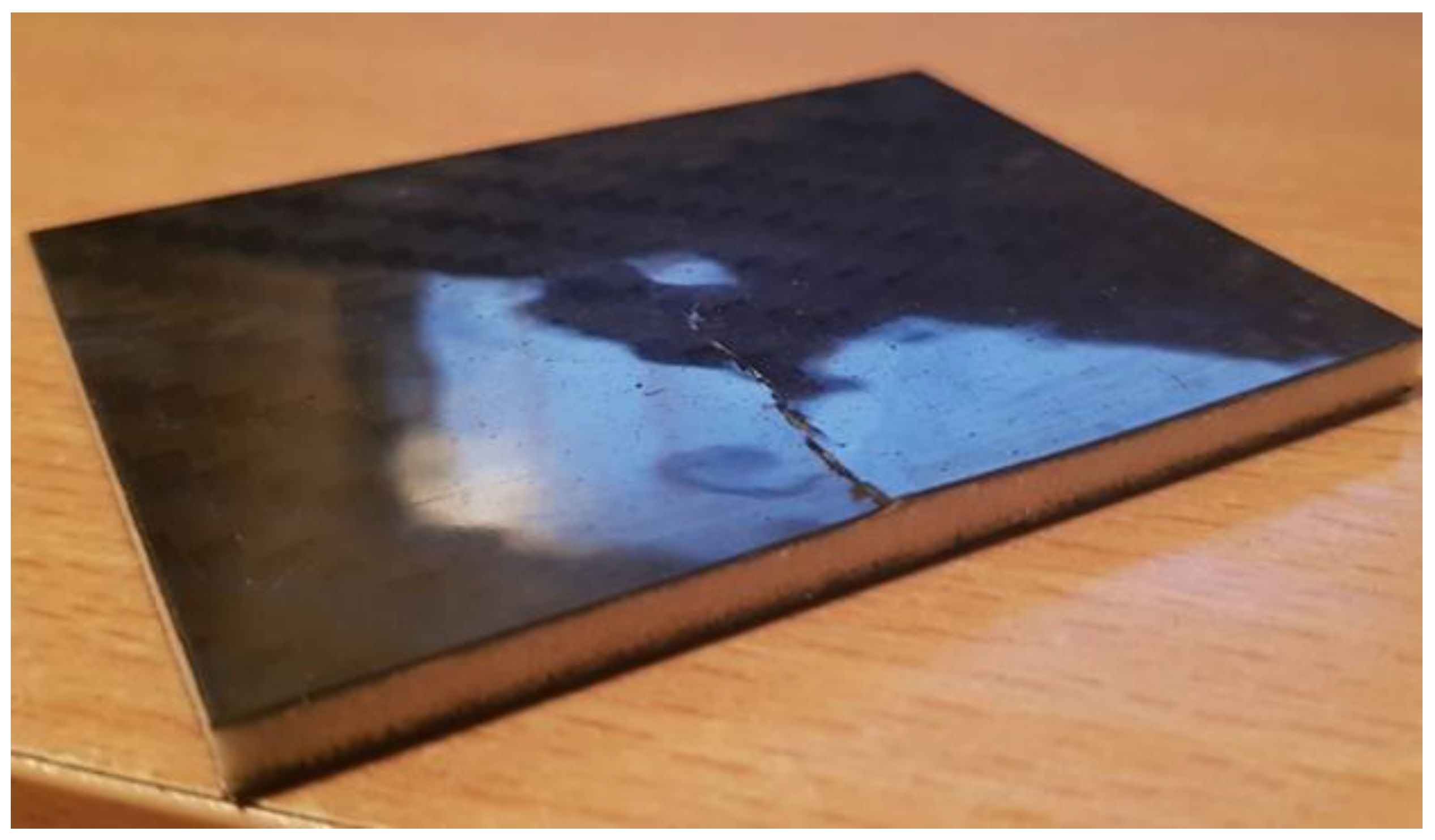
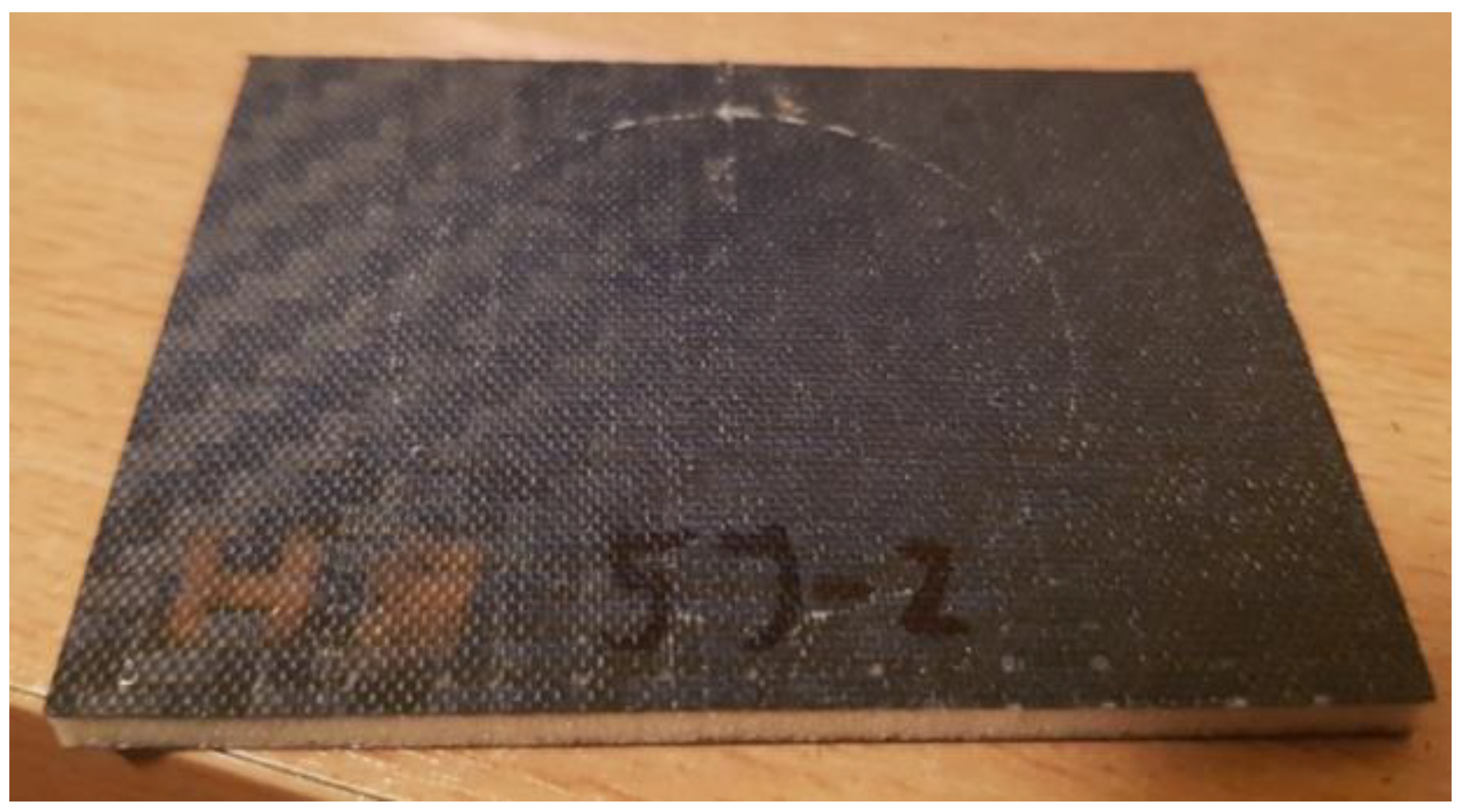
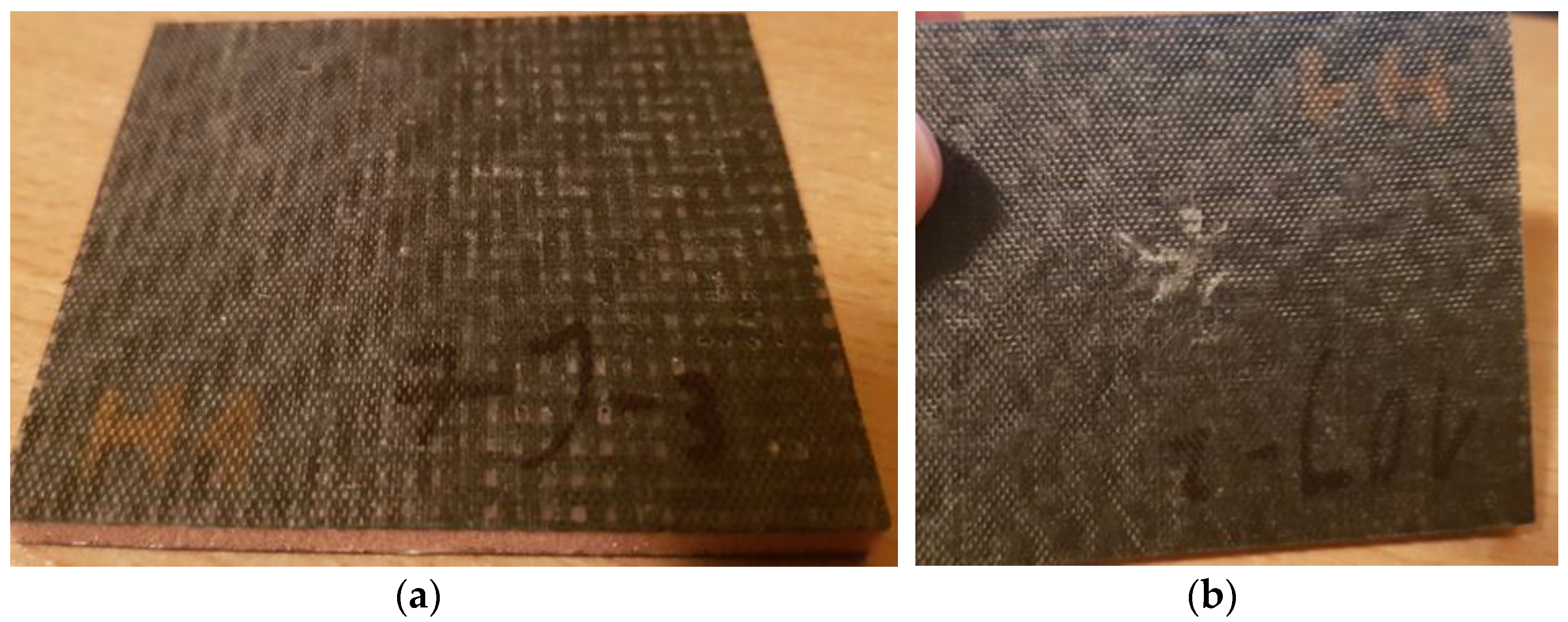
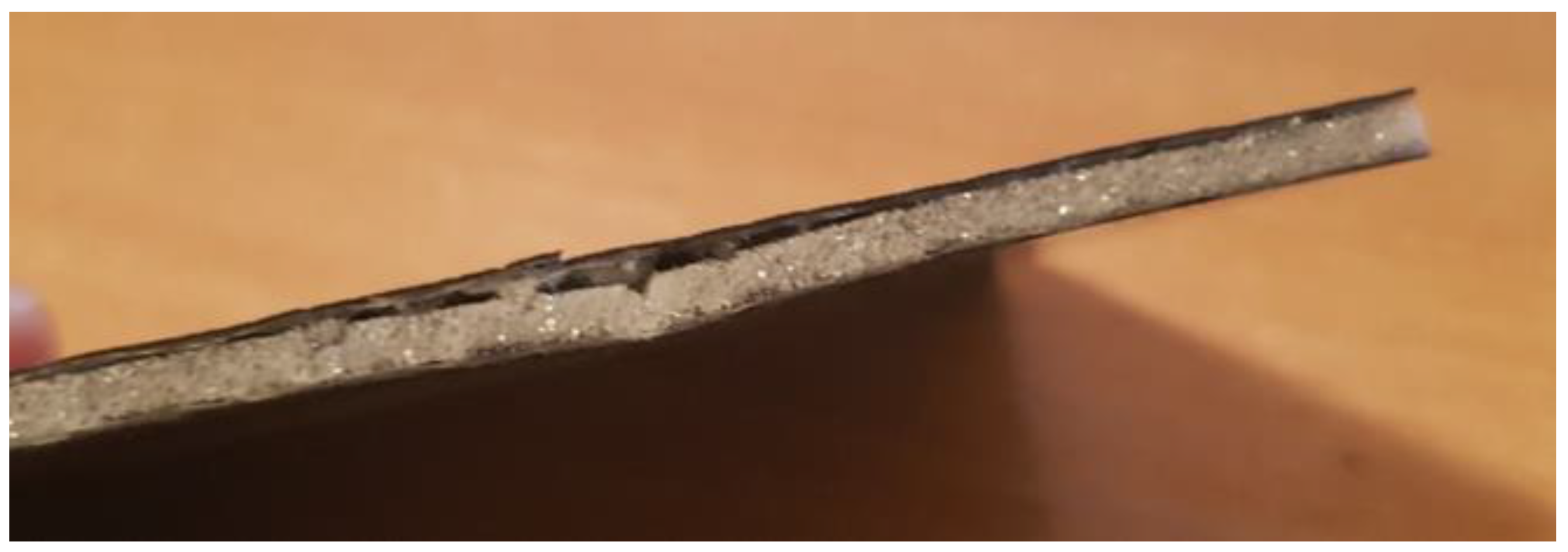
| Herex 55 (55 kg/m3) | 3.8 | Indentation in the impacted face. No visible damage to the second face. | Indentation in the impacted face Single cracks at indentation. Small (2–4 mm) cracks in the matrix base of the second face. | Indentation in the impacted face. Single cracks at indentation. Single crack in the second face. | Indentation in the impacted face. Single cracks at indentation. Single crack in the second face. | Denting in the impacted face and radial cracks. Significant losses and slight separation between the core and the face. Single crack in the second face. |
| Herex 75 (75 g/m3) | 4.2 | Indentation in the impacted face. No visible damage to the second face. | Indentation in the impacted face Single cracks at indentation. No visible damage to the second face. | Indentation in the impacted face. Single cracks at indentation. Single crack in the second face. | Indentation in the impacted face. Single cracks at indentation. Single crack in the second face. | Indentation in the impacted face Single cracks at indentation. Single crack in the second face. |
| Herex 90 (90 kg/m3) | 5 | Indentation in the impacted face. No visible damage to the second face. | Indentation in the impacted face. No visible damage to the opposite face. | Indentation in the impacted face. Single cracks at indentation. No visible damage to the second face. | Indentation in the impacted face. Single cracks at indentation. Chipping of the matrix and single fiber cracks of the second face. | Indentation in the impacted face Single cracks at indentation. Chipping of the matrix and single fiber cracks of the second face. |
| Airex (90 kg/m3) | 3 | Indentation in the impacted face. No visible damage to the second face. | Indentation in the impacted face, a single crack at the sample indentation and separation of the core from the face near the edge. Small (2–4 mm) cracks in the matrix base of the second face. | Indentation in the impacted face, a single crack at the specimen indentation and separation of the core from the cover near the edge. Single crack in the second face. | Indentation in the impacted face and a deformation as well as a single crack from the indentation to the edge of the specimen. Significant loss and separation between the core and face near the edge. Single crack in the second face. | Denting in the impacted face, deformation and a single crack to both sample edges, significant losses and separation between the core and the face along the entire length of the edge. Several cracks near the edge of the sample of the second face. |
Publisher’s Note: MDPI stays neutral with regard to jurisdictional claims in published maps and institutional affiliations. |
© 2022 by the authors. Licensee MDPI, Basel, Switzerland. This article is an open access article distributed under the terms and conditions of the Creative Commons Attribution (CC BY) license (https://creativecommons.org/licenses/by/4.0/).
Share and Cite
Komorek, A.; Przybyłek, P.; Szczepaniak, R.; Godzimirski, J.; Rośkowicz, M.; Imiłowski, S. The Influence of Low-Energy Impact Loads on the Properties of the Sandwich Composite with a Foam Core. Polymers 2022, 14, 1566. https://doi.org/10.3390/polym14081566
Komorek A, Przybyłek P, Szczepaniak R, Godzimirski J, Rośkowicz M, Imiłowski S. The Influence of Low-Energy Impact Loads on the Properties of the Sandwich Composite with a Foam Core. Polymers. 2022; 14(8):1566. https://doi.org/10.3390/polym14081566
Chicago/Turabian StyleKomorek, Andrzej, Paweł Przybyłek, Robert Szczepaniak, Jan Godzimirski, Marek Rośkowicz, and Szymon Imiłowski. 2022. "The Influence of Low-Energy Impact Loads on the Properties of the Sandwich Composite with a Foam Core" Polymers 14, no. 8: 1566. https://doi.org/10.3390/polym14081566
APA StyleKomorek, A., Przybyłek, P., Szczepaniak, R., Godzimirski, J., Rośkowicz, M., & Imiłowski, S. (2022). The Influence of Low-Energy Impact Loads on the Properties of the Sandwich Composite with a Foam Core. Polymers, 14(8), 1566. https://doi.org/10.3390/polym14081566