Abstract
In recent years, there has been a growing replacement of synthetic fibers by natural ones, particularly by autochthonous materials. In the case of Algeria, the most abundant plant resources are the PALF (Pineapple leaf fiber), the date palm, and the Alfa fibers. In this work, the development and use of analytical and numerical methods are proposed to predict the mechanical properties of layers based on natural fibers that will be applied to manufacture skins of the sandwich cylinder. To achieve these predictions, four analytical models were used, namely the Halpin–Tsai, the Chamis, the Hashin vs. Rosen, and the ROM. The analytical results were compared with the numerical simulations and experimental data. The prediction of the elastic properties of the three fiber-based eco-composites showed an important dispersion in terms of stiffness.
1. Introduction
The composites’ materials have low weight, high rigidity, and excellent energy absorption, making them ideal for structural applications compared to traditional materials [1,2]. A typical sandwich structure is one of the configurations of composite materials; it consists of two face sheets separated by a lightweight, thick core structure constructed of foam or honeycombs [3]. Sandwich cores are available in a variety of shapes and materials, including honeycomb and metals for aerospace, marine, piping, and vessel applications, depending on industry standards and functional needs [4].
Sandwich pipes for vessel storage are multilayered, comprised of multiple lightweight, synthetic fiber skins fully bonded to a polymeric core. They are an especially attractive concept because of their high strength, stiffness-to-weight ratios, and corrosion resistance [5,6].
The synthetic fibers, which are used in the fabrication of the skin sandwich, have many disadvantages: they are far less biodegradable and have less desirable cost and availability in comparison with natural fibers [7].
Several research studies focus on the replacement of synthetic skins by eco-composites based on natural fibers [8,9,10] in a sandwich structure, such as palm, kenaf, banana, ramie, jute, leaf spring, flax, hemp, pineapple, and Alfa [11,12,13,14,15,16,17,18]. This interest is justified because of their widespread availability, lightness, strength [19,20], biodegradability, sustainable and renewable nature [21,22], in addition to their high specific modulus and low cost [16,23], low wear of tooling, skin irritation, and environmentally-friendliness [24,25]. Natural fiber composites, as opposed to synthetic fiber composites, may provide more effective recycling solutions due to their bio-based feedstock and capacity to generate additional energy during incineration [23,26]. Bio-based composites appear to be very promising alternatives to traditional composites, as they have lower densities and, as a result, particular property/density ratios comparable to glass fibers [27]. These properties reveal a new horizon for researchers to replace the synthetic fiber reinforcements in composites [28].
Before achieving the sizing of the tubular eco-sandwich cylinder, a multiscale characterization is performed, beginning with the micro and macro-mechanical scales. The micromechanical approach (part 1) is used to predict the mechanical properties of bio skins. Before analyzing the whole cylinder sandwich structure under different loading, the second step focuses on understanding the behavior of a sandwich element in the tubular structure through a macro-mechanical model (part 2).
A large number of Finite Element Models (FEM) and analytical micromechanical models have been proposed in the literature for predicting various mechanical properties of composite materials [29,30,31,32]. For the FEM model, the representative volume elements (RVE) of bio-composites were established in different software, such as ANSYS, ABAQUS, and DIGIMAT [30,31,32], to determine the micromechanical properties and failure mechanism of bio-composites. Currently, many researchers are attempting to anticipate the natural fiber polymer composite’s mechanical performance using various mathematical and numerical methods. The rule of mixtures (ROM), inverted ROM (IROM), Halpin–Tsai model, Cox model, Kelly–Tyson model [32], and Mori–Tanaka model [33,34,35,36] are the most widely used and well-known theories for defining mechanical characteristics. In addition, several additional models, such as the bridging model, Hashin and Rosen, Double-Inclusion model [37], Christensen equation, and Chamis model, have been used to determine the mechanical properties of composite materials.
This first part of the contribution aims to predict the mechanical properties of skin layers made from PALF (Pineapple leaf fiber), date palm, and Alfa fibers, which are among Algeria’s most abundant plant resources, at different volume fractions. To this end, micromechanical analytical and FEM models have been developed under MATLAB 8.3 and ANSYS 18.1 software. The influence of the volume fraction of reinforcement on Young’s and shear modulus and Poisson’s ratios is studied.
The analytical models are based on four theories, Halpin–Tsai, Chamis, Hashin vs. Rosen, and ROM. To choose a suitable theory from them that is in good agreement with the experimental data obtained by Rakesh [13], a comparison is made for the composite made from PALF fibers.
The suitable theory is used with the FEM model to predict the mechanical properties of skin layers made from PALF, date palm, and Alfa fibers, where the results are inefficient in combination. The FEM used four RVE, depending on the volume fraction of natural fibers.
2. Materials and Methods
The different material properties of both the matrix and fiber are shown in Table 1. By altering the volume fraction of the fiber, material properties are utilized to establish the mechanical properties of the composites, which are the longitudinal Young’s modulus (), transverse Young’s modulus (), longitudinal shear modulus (), and major Poisson’s ratio ().

Table 1.
Properties of the constituents.
Figure 1 shows the different natural fiber plants used in this paper.
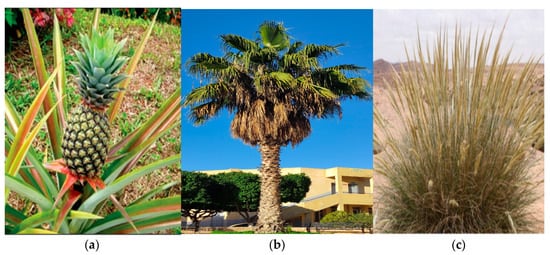
Figure 1.
Natural fiber plants: (a) Pineapple [40], (b) Palm and (c) Alfa [12].
2.1. Analytical Analysis
Many studies have focused on predicting the mechanical properties of composites. To evaluate the elastic properties of composites, different micromechanical models have been proposed, such as the Halpin–Tsai model, the Chamis model, the rule of mixtures (ROM), and the Hashin and Rosen model. The analytical models were derived from [41]. The equations of these four models are written as:
- Halpin–Tsai model
- Chamis model
- ROM model
- Hashin and Rosen model
2.2. FEM Analysis
2.2.1. Fiber-Reinforced Composite Numerical Homogenization
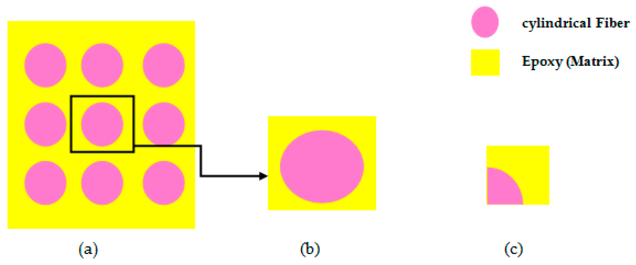
Epoxy and one of the fibers (PALF, Palm fiber, or Alfa fiber) are the main components of the Particle Reinforced Composite. To accomplish the analysis, the homogenization approach is used for a fiber-reinforced composite by selecting continuous fibers as reinforcement. Figure 2 illustrates a uniform distribution of fiber in the epoxy, by using the finite element software ANSYS 18.1 to solve the problem.
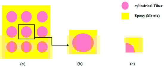
Figure 2.
(a) Uniform distribution of fibers in the matrix; (b) Isolated Unit cell; (c) One-eighth Model.
2.2.2. Element Type
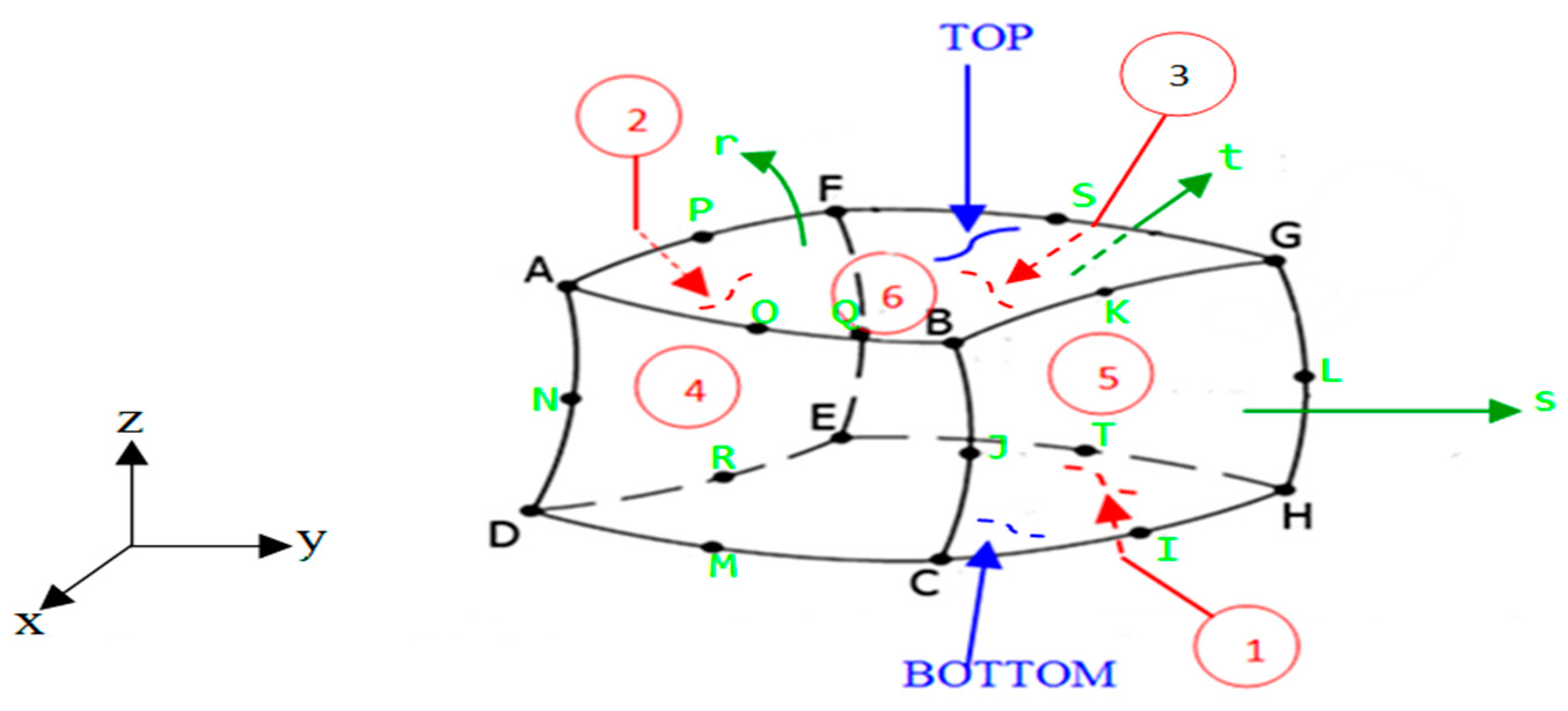
The ANSYS SOLID 186 element [42] is shown in Figure 3, which is a higher-order 3D 20-node solid element with quadratic displacement behavior, was used in this study. There are 20 nodes in the element, each with three degrees of freedom (DOF) (translations in the three nodal directions).
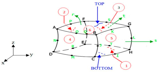
Figure 3.
The element used for meshing the finite element models.
2.2.3. Geometry and Finite Element Modeling
The representative volume element (RVE) used for the hybrid analysis has the form of a square cube. Due to the symmetry in geometry, loading, and boundary conditions, only one-fourth of the RVE’s cross-section is modeled and studied. As one-fourth of the unit cell is used for FE modeling, the FE model consists of a rectangular prism with dimensions x = 100 mm, y = 100 mm, and z = 10 mm, with an embedded one-fourth portion of continuous fiber (PALF, Palm, or Alfa fiber) of radius at one of the square cube’s corners, which is the center of the tubular fiber, where the length of the fiber is taken as 10 mm. As a result, the analysis will be faster and computational time will be lowered.
The radius of the fiber is calculated for various weight percentages of the fibers. The weight percentages are converted into volume fractions. Four different volume fractions of fiber have been studied for the analysis, ranging from 15% to 24% with an increment of 3% of the volume fraction of the fiber. Thus, the following (17) is obtained:
where is the radius of the cylindrical fiber is the volume fraction of the fiber.
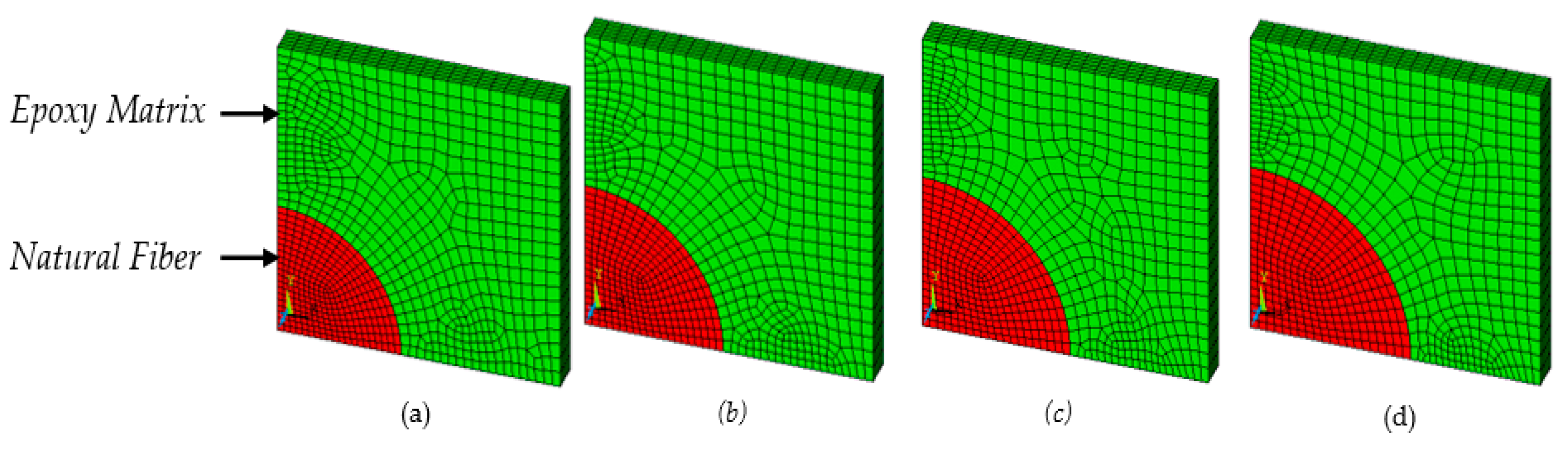
Figure 4 gives an example of the converged mesh models of a composite at different volume fractions of natural fibers.
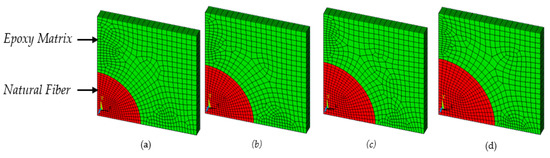
Figure 4.
Converged mesh models of composite (RVE dimension) at: (a) 15%; (b) 18%; (c) 21% and (d) 24% of volume fraction of natural fibers.
2.2.4. Loading and Boundary Conditions
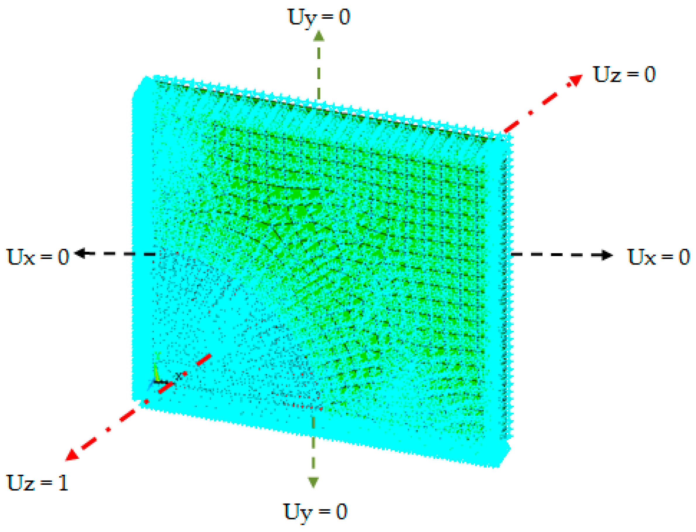
The finite element model is subjected to boundary conditions that force it to behave as if it were a component of the entire array of composite materials. One-eighth of the unit cell is modeled in the analysis due to symmetry in loads, geometry, and boundary conditions. The mentioned symmetrical boundary conditions were unit displacement from the symmetry of the problem. An overlapped volume connection is used between the fiber and the matrix.
A value displacement load of 1 mm is applied to the face to establish a uniaxial state of stress in that direction, allowing the Young’s modulus and Poisson’s ratio of the resultant composite to be predicted using simple Hook’s law. The uniaxial state of displacement on the surface z = 10 mm is used to estimate longitudinal Young’s modulus and Poisson’s Ratio .
The area at x = 100 mm is exposed to a uniaxial displacement condition to predict transverse Young’s modulus. A uniaxial stress condition is given to the area at y = 100 mm to predict shear modulus. In Figure 5, it is possible to see the boundary conditions.
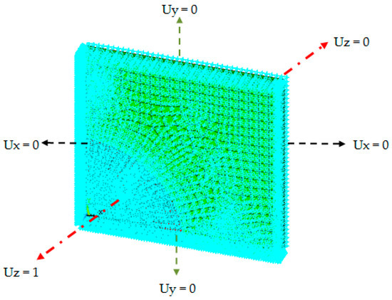
Figure 5.
Loading and boundary conditions of the numerical model for predicting .
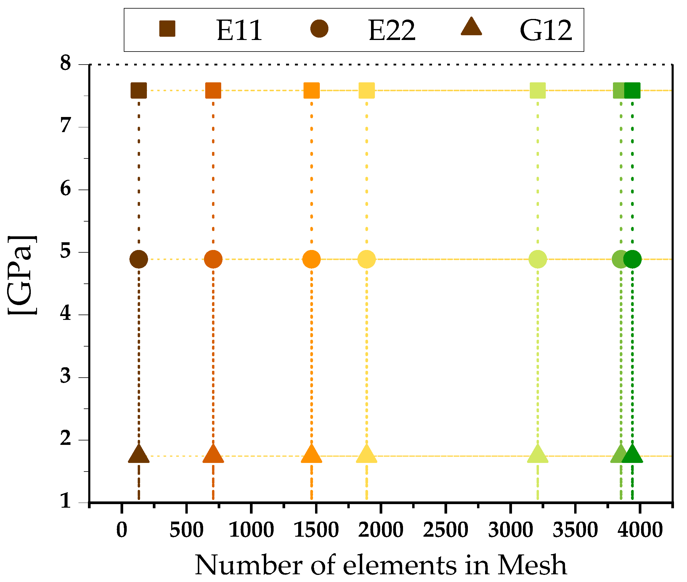
A mesh convergence is performed on the longitudinal Young’s modulus of PALF at a 15% volume fraction to verify the accuracy of our findings. It is clear that we have arrived at a converged solution. The results of the FEA model are independent of mesh size.
The results of the convergence analyses based on changing the number of elements in the mesh are summarized in Figure 6.
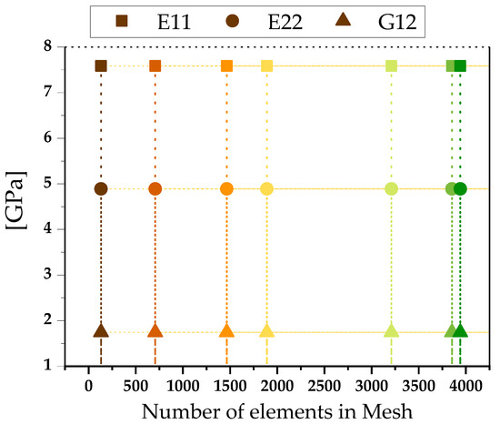
Figure 6.
Mesh convergence analysis for finite elements of: , and at 15% of volume fraction of natural fiber.
For varied mesh sizes, Figure 6 illustrates a fairly similar study for: longitudinal Young’s modulus , Transverse Young’s modulus and shear modulus . It demonstrates that the FEA model’s results are unaffected by the number of elements in the mesh.
By choosing a unit value of applied strain, and once the problem defined by the boundary conditions is solved, it is possible to compute the stress field , whose average gives the required components of the elastic matrix, one column at a time, as:
where:. The integral sin (18) is evaluated within each finite element using the Gauss–Legendre quadrature. Commercial programs, such as ANSYS®, have the capability to compute the average stress and volume, element by element [42].
For the elastic domain:
3. Results and Discussion
The results of the analytical models developed for the fiber reinforced composite are compared to the experimental results for the PALF/epoxy unidirectional composite from Rakesh’s study [13], as shown in figures below.
The predicted results for all the analyzed models agree with the experimental data for composites (PALF/epoxy) with varying volume fractions. To characterize the tensile properties, unidirectional composite specimens were manufactured according to the necessary standard. The specimens were 160 mm, 12.5 mm, and 3 mm in size, respectively. For each volume fraction of the fiber, five identical samples were manufactured, and all specimens were examined using an electronic tensometer at a strain rate of 0.5 mm/min. Single fiber testing was used to characterize the PALF fiber’s tensile modulus according to the ASTM D3379 standard. A total of 23 specimens were evaluated in order to obtain an exact figure for the PALF fiber’s property [13]. The composites’ longitudinal Young’s modulus increases as the volume fraction of fiber rises, as can be shown in Figure 7.
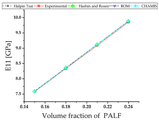
Figure 7.
Comparison (analytical vs. exp) of Longitudinal Young’s modulus of PALF/epoxy in terms of volume fractions.
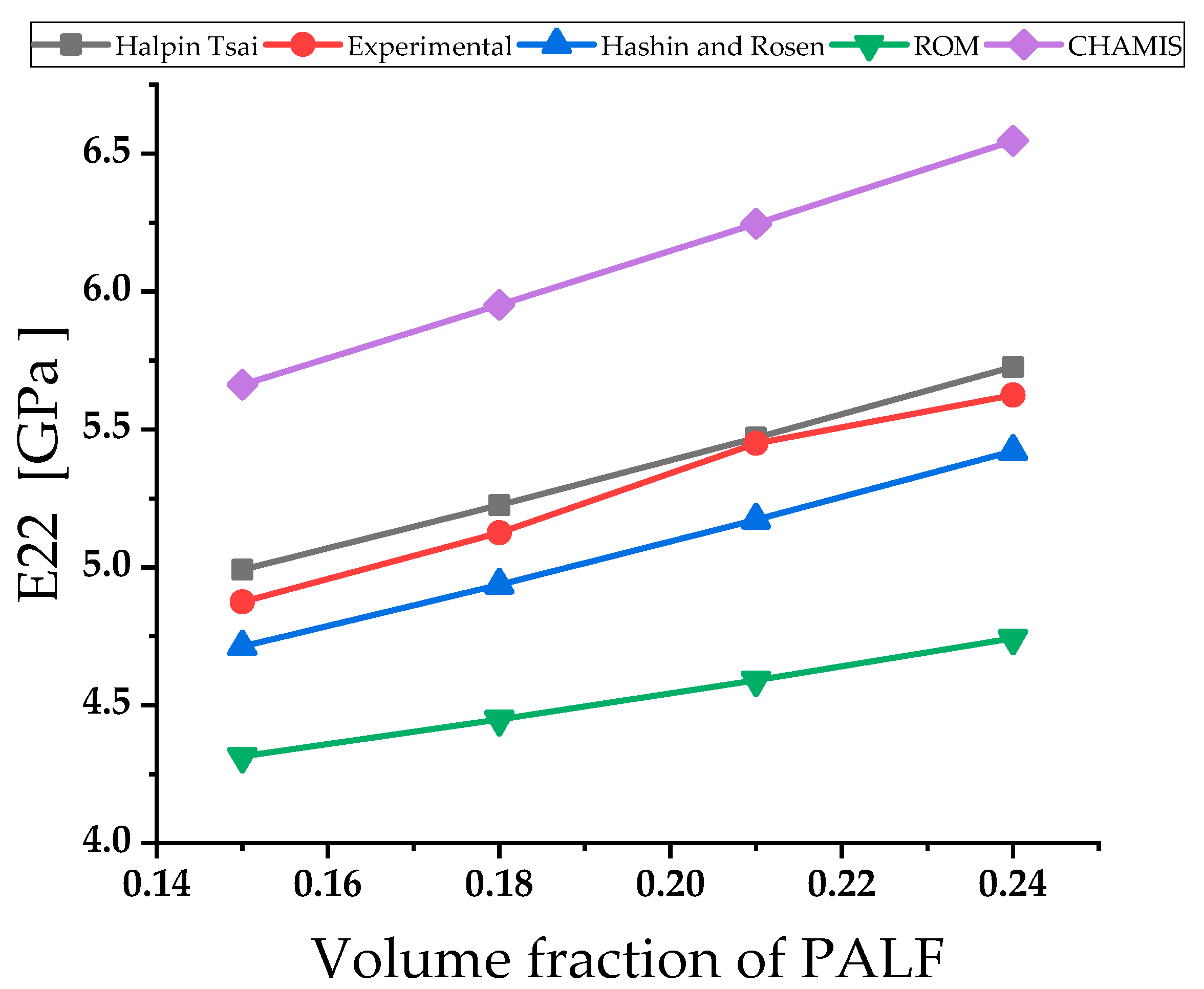
Figure 8 shows that the transverse Young’s modulus of composites increases along with the volume fraction of fiber, but the increment is lower when compared with the magnitude of . The closest agreement with the experimental results belongs to Halpin Tsai model.
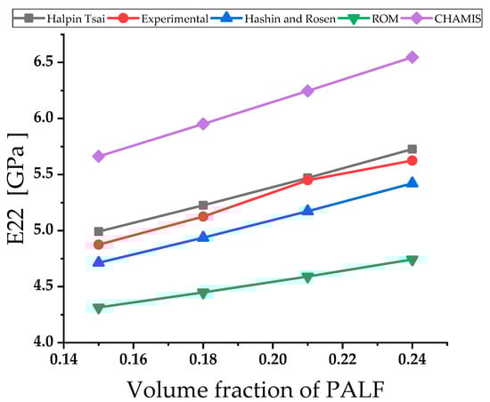
Figure 8.
Transverse Young’s modulus of PALF /epoxy in terms of different volume fractions of fiber.
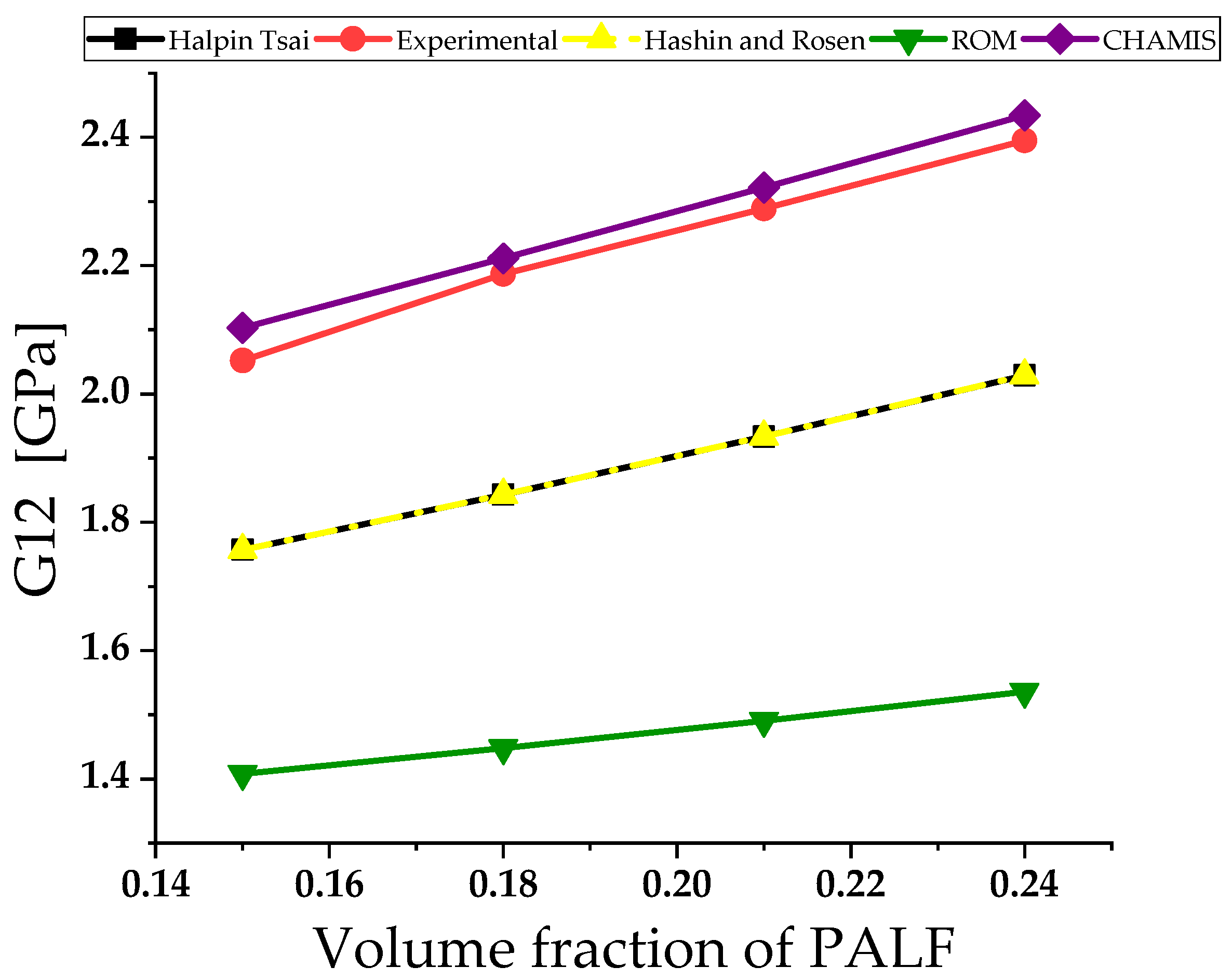
The analytical analysis results are compared to the experimental data in Figure 9. When compared to experimental data, the results generated by the analytical model of Chamis offer remarkably similar results.

Figure 9.
The comparison of shear modulus of PALF/epoxy in terms of volume fractions.
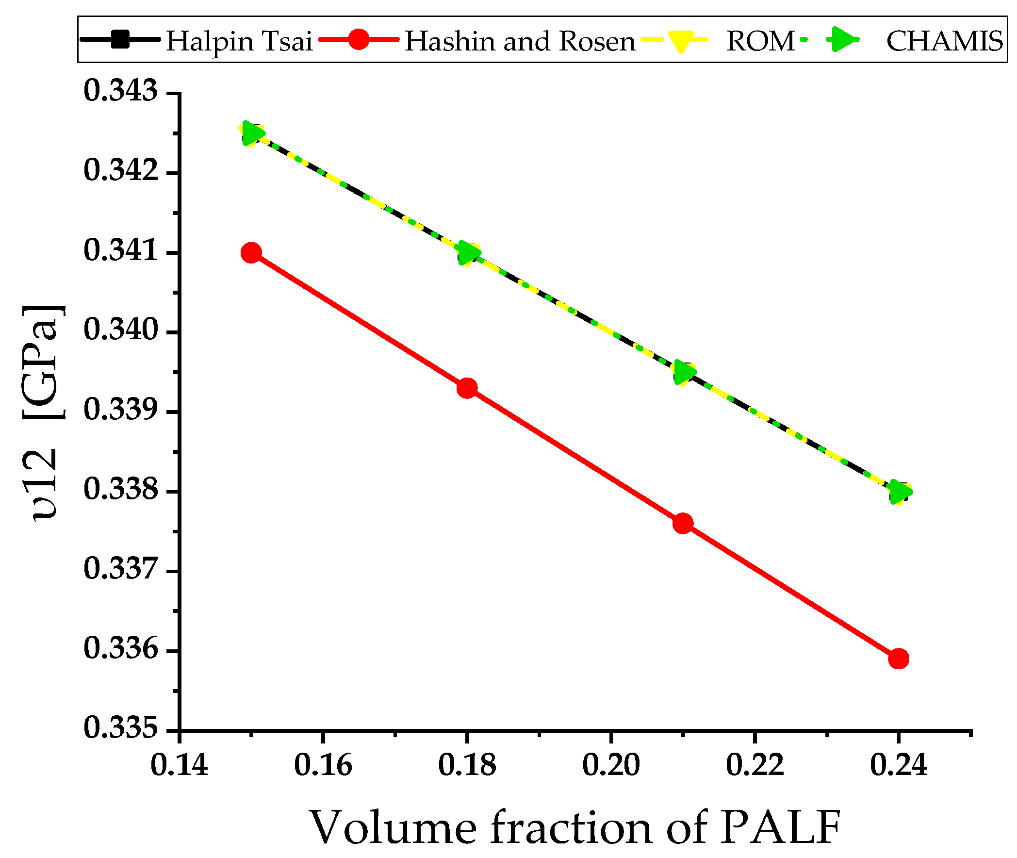
It can be seen that the predicted values of the Poisson’s ratio for all tested models are in good agreement; this is illustrated in Figure 10.
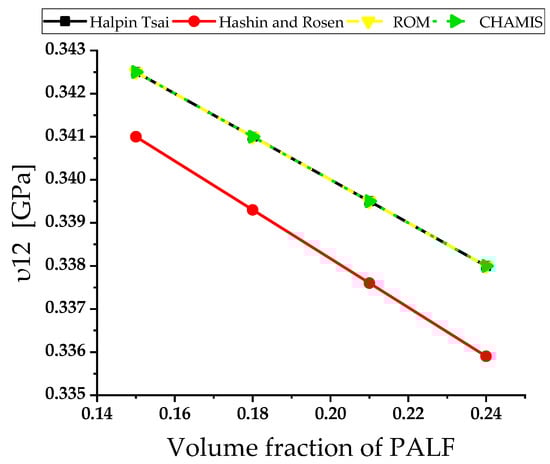
Figure 10.
The Poisson’s ratio of PALF/epoxy in terms of .
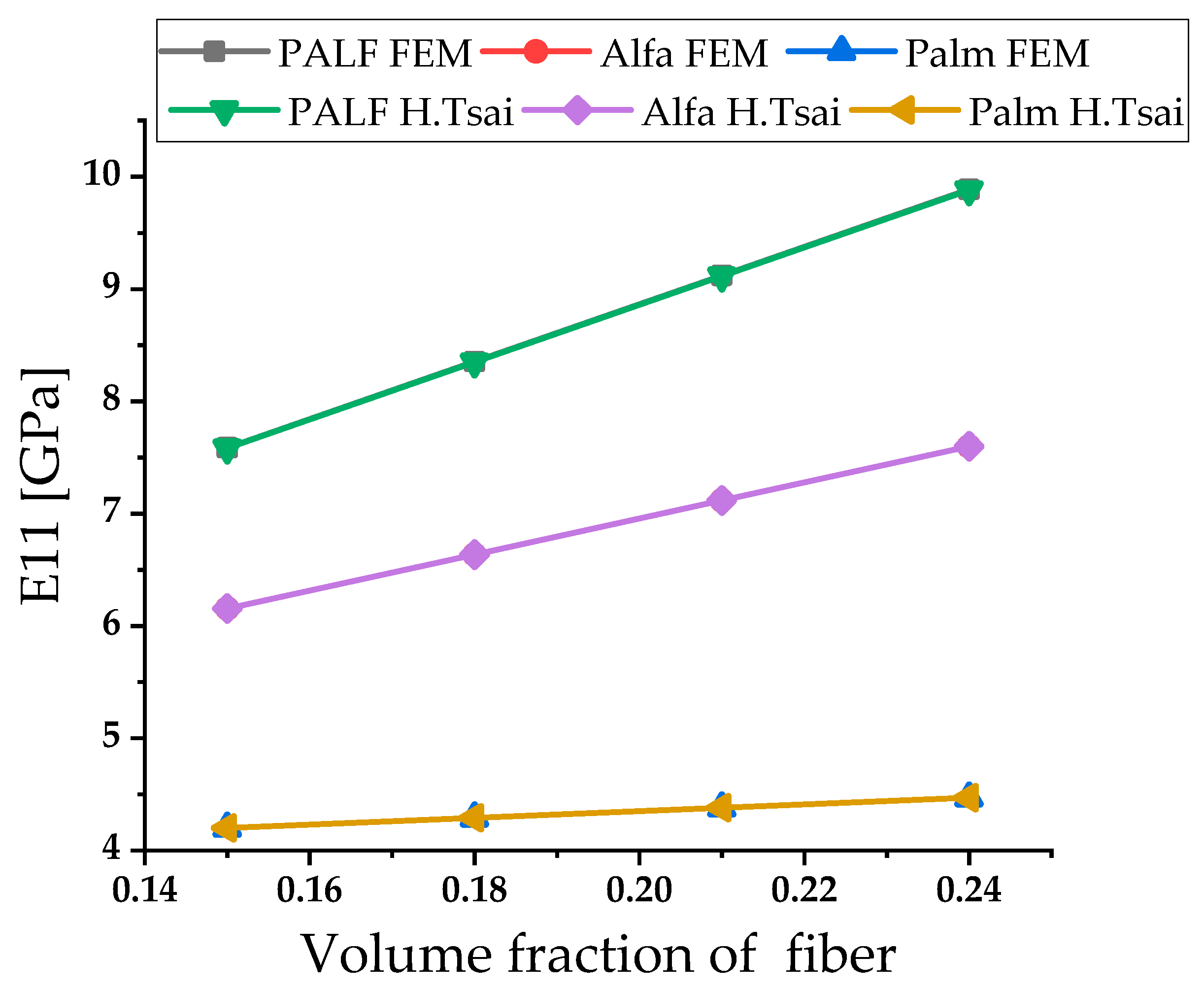
The first analytical part permitted us to select the analytical method that allows us to have mechanical properties that best converge with the experimental results. To forecast and , the Halpin-Tsai approach was chosen. For , it is Chamis, and for , it is ROM. A FEM approach is established and compared with the results of the analytical analysis in order to strengthen our prediction.
The variation of and as a function of the volume fraction of natural fibers, obtained by Halpin-Tsai and numerical analysis.
For all composites with varied , the predicted results of FEM for are in agreement with the analytical results. These examples are depicted in Figure 11. The prediction of the longitudinal modulus shows that the composite based on PALF fibers presents the best behavior in tension.

Figure 11.
Predicted analytical (Halpin–Tsai model) and numerical results for in terms of .
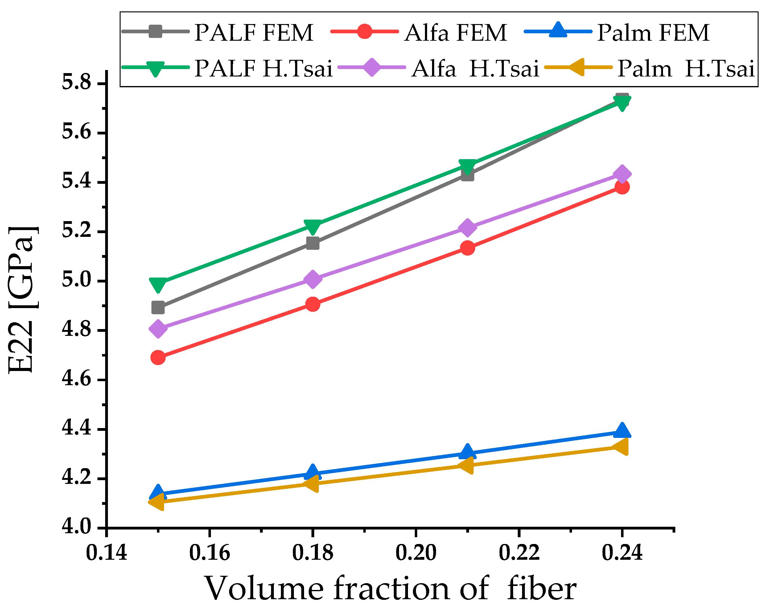
The FEM anticipated results are in good correlation with the analytical results. Figure 12 shows a comparison of the results obtained for using the FEM and the analytical analysis. The prediction of the transverse modulus show that the composite based on PALF fibers presents the best behavior in compression.
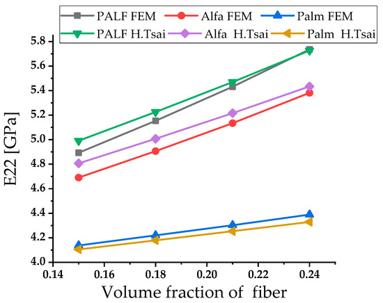
Figure 12.
Predicted analytical (Halpin–Tsai model) and numerical results for in terms of .
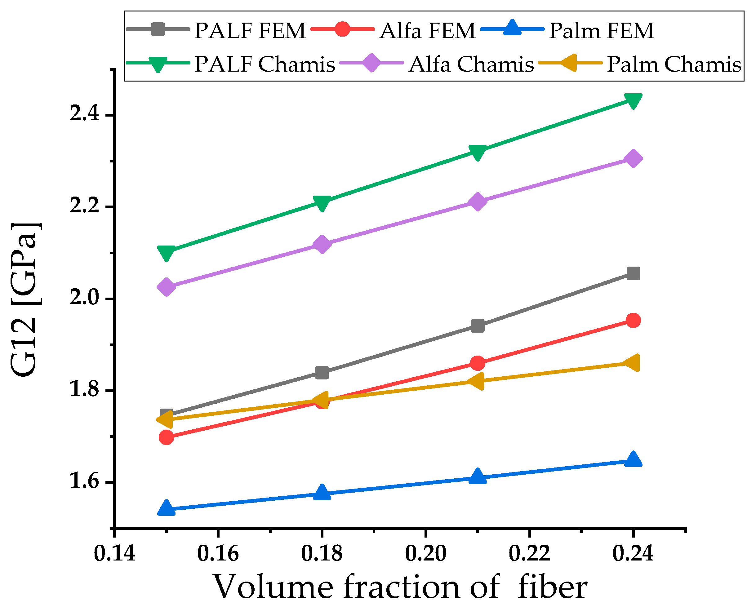
Chamis and numerical analysis were used to determine the variation of as a function of the volume fraction of natural fiber. When compared to analytical results, the numerical approach of finite element analysis yields good results, this can be found in Figure 13. The prediction of the shear modulus shows that the composite based on PALF fibers presents the best behavior in shear.
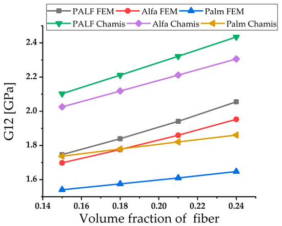
Figure 13.
Predicted analytical (Chamis model) and numerical results for Shear Modulus in terms of .
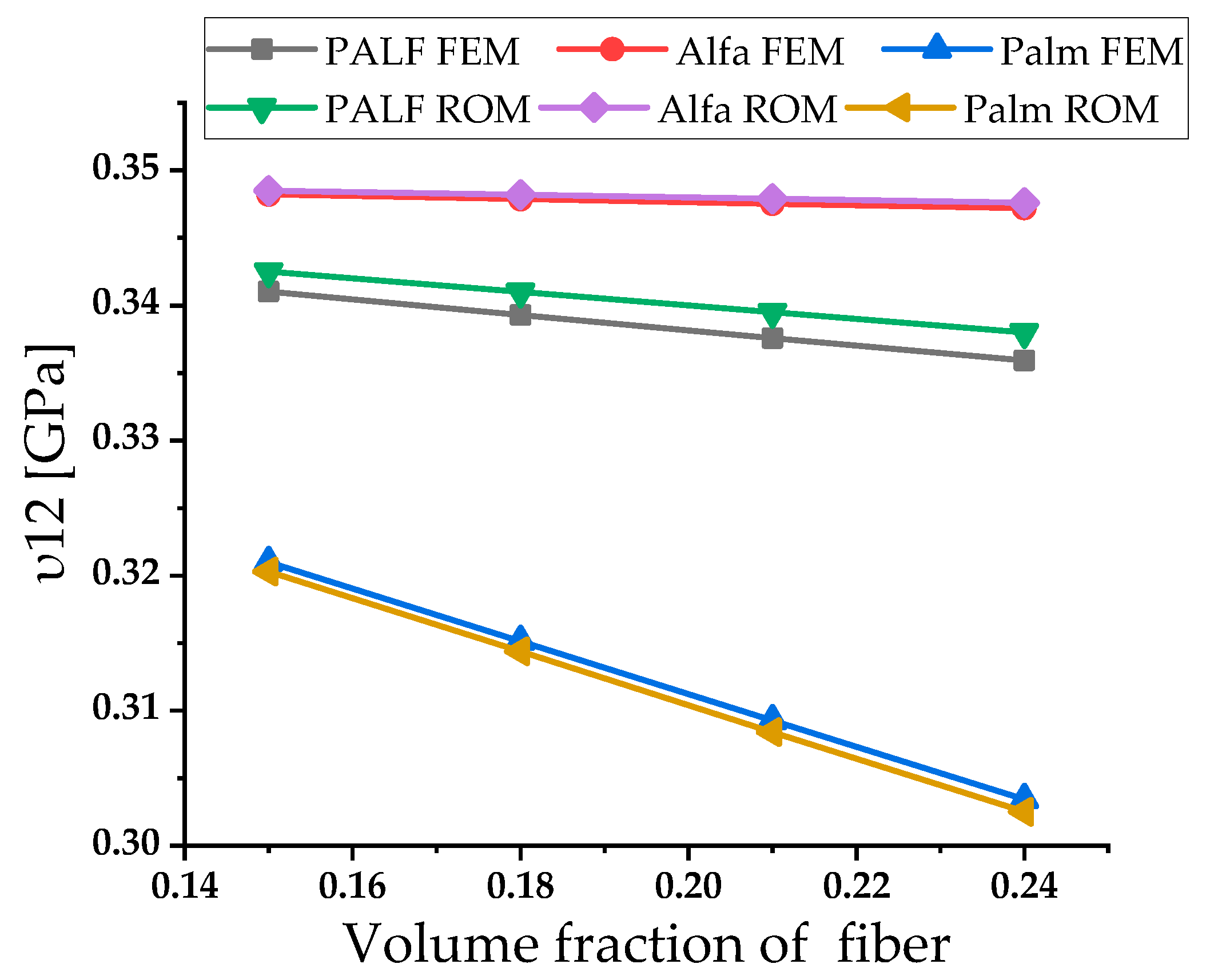
Concerning the major Poisson’s ratio, the results were obtained only from the ROM model and the FEM. Concerning the Poisson’s ratios, the obtained results of the analytical models show that the Alfa/epoxy has the highest Poisson’s ratio compared to PALF/epoxy and palm/epoxy. Figure 14 shows that for the major Poisson’s ratio , all analytical and numerical models correlate well with each other.
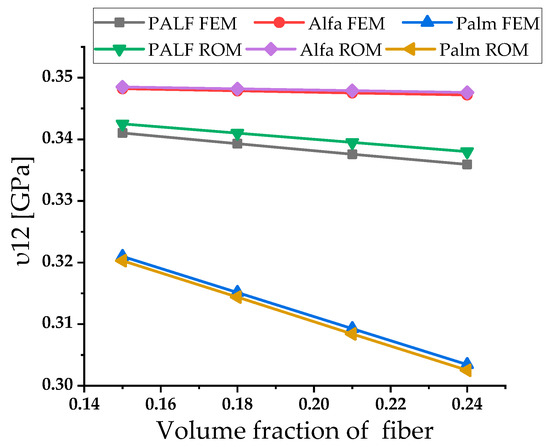
Figure 14.
Predicted analytical (ROM model) and numerical results of Poisson’s ratios in terms of .
4. Conclusions
In the present work, models were developed and used analytical and numerical methods to predict some mechanical properties of composite layers based on natural fibers. To accomplish these goals, we used four micromechanical analytical models, namely the Halpin–Tsai, the Chamis, the Hashin vs. Rosen, and the ROM. The analytical results were compared to the numerical simulations (FEM) and experimental data. The analyzed composites have a matrix of epoxy resin which is reinforced by the natural fibers, PALF, DB date palm tree fiber and Alfa fiber.
Based on this study, it is possible to summarize the following conclusions:
- The change in volume fraction of fiber has a significant effect on elastic properties.
- The Young’s modulus rises in tandem with the reinforcement weight percentage.
- The Poisson’s ratio decreases as the weight fraction of reinforcement increases.
- The shear modulus is calculated using the analytical expression, and it is also increasing along with the reinforcement.
- The mechanical properties of , , , determined by the analytical micromechanical models agree with the experimental results.
- The analytical micromechanical models allow us to select the most appropriate theory used to determine the mechanical properties of PALF fibers that best fits to the experimental results. To forecast and , the Halpin–Tsai approach was chosen. For , it is Chamis, and for , it is ROM.
- The most appropriate theory was used with the FEM model to predict the mechanical properties of skin layers based on PALF, date palm and Alfa fibers, where the results are in efficient consensus.
- The present work shows the successful prediction of elastic properties of composites by Finite Element Analysis.
However, the predictions for the elastic properties of the three fiber-based eco-composites showed a strong dispersion in terms of stiffness. Nevertheless, in future works, it is possible to test several fiber combinations to determine the best combination that has high values for mechanical properties in all directions. With this information, it is feasible to manufacture the composite without trying each combination with experimental tests, which will be a costly and time-intensive process.
Author Contributions
Conceptualization, G.H., A.H., J.R.; Data curation, G.H. and A.H.; Investigation, G.H., A.M. and A.H.; Methodology, G.H., A.M., A.H. and J.R.; Resources, G.H., A.M., A.H., J.R. and M.H.D.; Software, G.H., A.M. and A.H.; Supervision, A.H. and J.R.; Validation, G.H., A.M. and A.H.; Writing—original draft, G.H., A.H., J.R. and M.H.D. All authors have read and agreed to the published version of the manuscript.
Funding
This work has been funded partially by Portuguese national funds of FCT/MCTES (PIDDAC) through the base funding from the UIDB/00690/2020 (CIMO) research unit.
Conflicts of Interest
The authors declare no conflict of interest.
References
- Maizia, A.; Hocine, A.; Dehmous, H.; Chapelle, D. Prediction of reliability analysis of composite tubular structure under hygro-thermo-mechanical loading. Mech. Adv. Mater. Struct. 2019, 26, 372–379. [Google Scholar] [CrossRef]
- Chapelle, D.; Hocine, A.; Carbillet, S.; Boubakar, M. Analysis of intermetallic swelling on the behavior of a hybrid solution for compressed hydrogen storage–Part II: Finite element method simulation. Mater. Des. 2012, 36, 459–469. [Google Scholar] [CrossRef]
- Tarlochan, F. Sandwich structures for energy absorption applications: A review. Materials 2021, 14, 4731. [Google Scholar] [CrossRef]
- Sanjay, M.R.; Arpitha, G.R.; Naik, L.L.; Gopalakrishna, K.; Yogesha, B. Applications of natural fibers and its composites: An overview. Nat. Resour. 2016, 7, 108–114. [Google Scholar] [CrossRef] [Green Version]
- Xia, M.; Takayanagi, H.; Kemmochi, K. Bending behavior of filament-wound fiber-reinforced sandwich pipes. Compos. Struct. 2002, 56, 201–210. [Google Scholar] [CrossRef]
- Hastie, J.C.; Kashtalyan, M.; Guz, I.A. Analysis of filament-wound sandwich pipe under combined internal pressure and thermal load considering restrained and closed ends. Int. J. Press. Vessel. Pip. 2021, 191, 104350. [Google Scholar] [CrossRef]
- Lotfi, A.; Li, H.; Dao, D.V.; Prusty, G. Natural fiber–reinforced composites: A review on material, manufacturing, and machinability. J. Thermoplast. Compos. Mater. 2019, 34, 238–284. [Google Scholar] [CrossRef]
- CoDyre, L.; Fam, A. Axial Strength of Sandwich Panels of Different Lengths with Natural Flax-Fiber Composite Skins and Different Foam-Core Densities. J. Compos. Constr. 2017, 21, 04017042. [Google Scholar] [CrossRef]
- Sadeghian, P.; Hristozov, D.; Wroblewski, L. Experimental and analytical behavior of sandwich composite beams: Comparison of natural and synthetic materials. J. Sandw. Struct. Mater. 2018, 20, 287–307. [Google Scholar] [CrossRef]
- Alhijazi, M.; Zeeshan, Q.; Qin, Z.; Safaei, B.; Asmael, M. Finite element analysis of natural fibers composites: A review. Nanotechnol. Rev. 2020, 9, 853–875. [Google Scholar] [CrossRef]
- Sailesh, A.; Arunkumar, R.; Saravanan, S. Mechanical properties and wear properties of kenaf–aloe vera–jute fiber reinforced natural fiber composites. Mater. Today: Proc. 2018, 5, 7184–7190. [Google Scholar] [CrossRef]
- El-Abbassi, F.E.; Assarar, M.; Ayad, R.; Bourmaud, A.; Baley, C. A review on alfa fibre (Stipa tenacissima L.): From the plant architecture to the reinforcement of polymer composites. Compos. Part A: Appl. Sci. Manuf. 2019, 128, 105677. [Google Scholar] [CrossRef]
- Potluri, R.; Diwakar, V.; Venkatesh, K.; Reddy, B.S. Analytical model application for prediction of mechanical properties of natural fiber reinforced composites. Mater. Today: Proc. 2018, 5, 5809–5818. [Google Scholar] [CrossRef]
- Ashwini, K.; Rao, C.M. Design and analysis of leaf spring using various composites—An overview. Mater. Today: Proc. 2018, 5, 5716–5721. [Google Scholar] [CrossRef]
- Dragonetti, R.; Napolitano, M.; Boccarusso, L.; Durante, M. A study on the sound transmission loss of a new lightweight hemp/bio-epoxy sandwich structure. Appl. Acoust. 2020, 167, 107379. [Google Scholar] [CrossRef]
- Sapiai, N.; Jumahat, A.; Mahmud, J. Mechanical properties of functionalised CNT filled kenaf reinforced epoxy composites Mechanical properties of functionalised CNT fi lled kenaf reinforced epoxy composites. Mater. Res. Express 2018, 5, 045034. [Google Scholar] [CrossRef]
- Elzayady, N.E.; Elghandour, E.I. Fracture resistance of composite structurs from hemp bio-fibers. J. Adv. Eng. Trends 2021, 40, 137–147. [Google Scholar] [CrossRef]
- Boria, S.; Raponi, E.; Sarasini, F.; Tirillò, J.; Lampani, L. Green sandwich structures under impact: Experimental vs numerical analysis. Procedia Struct. Integr. 2018, 12, 317–329. [Google Scholar] [CrossRef]
- Safri, S.N.A.; Sultan, M.T.H.; Jawaid, M.; Jayakrishna, K. Impact behaviour of hybrid composites for structural applications: A review. Compos. Part B: Eng. 2018, 133, 112–121. [Google Scholar] [CrossRef]
- Kiruthika, A. A review on physico-mechanical properties of bast fibre reinforced polymer composites. J. Build. Eng. 2017, 9, 91–99. [Google Scholar] [CrossRef]
- Zhang, K.-L.; Zhang, J.-Y.; Hou, Z.-L.; Bi, S.; Zhao, Q.-L. Multifunctional broadband microwave absorption of flexible graphene composites. Carbon 2019, 141, 608–617. [Google Scholar] [CrossRef]
- Alsubari, S.; Zuhri, M.Y.M.; Sapuan, S.M.; Ishak, M.R.; Ilyas, R.A.; Asyraf, M.R.M. Potential of natural fiber reinforced polymer composites in sandwich structures: A review on its mechanical properties. Polymers 2021, 13, 423. [Google Scholar] [CrossRef] [PubMed]
- Monteiro, S.N.; Lopes, F.P.D.; Ferreira, A.S.; Nascimento, D.C.O. Natural-fiber polymer-matrix composites: Cheaper, tougher, and environmentally friendly. JOM 2009, 61, 17–22. [Google Scholar] [CrossRef]
- Nurazzi, M.; Khalina, A.; Laila, D. A review: Fibres, Polymer Matrices and Composites. Pertanika J. Sci. Technol. 2017, 25, 1085–1102. [Google Scholar]
- Lee, C.; Khalina, A.; Lee, S. Importance of interfacial adhesion condition on characterization of plant-fiber-reinforced polymer composites: A review. Polymers 2021, 13, 438. [Google Scholar] [CrossRef]
- Campilho, R.D.S. Natural Fiber Composites; CRC Press: London, UK; New York, NY, USA, 2016; Volume 49. [Google Scholar]
- Monti, C. Arthur Élaboration et Caractérisation d’une De, Structure Composite Sandwiche à Base Naturels; l’Université du Maine: Le Mans, France, 2016. [Google Scholar]
- Ali, A.; Shaker, K.; Nawab, Y.; Jabbar, M.; Hussain, T.; Militky, J.; Baheti, V. Hydrophobic treatment of natural fibers and their composites—A review. J. Ind. Text. 2018, 47, 2153–2183. [Google Scholar] [CrossRef]
- Pan, Y.; Iorga, L.; Pelegri, A.A. Numerical generation of a random chopped fiber composite RVE and its elastic properties. Compos. Sci. Technol. 2008, 68, 2792–2798. [Google Scholar] [CrossRef]
- Benabbes, A.; Siad, L.; Dormieux, L.; Liu, W.K.; Barlat, F.; Moon, Y.H.; Lee, M.G. A homogenization approach to the yield strength of spherical powder compacts. AIP Conf. Proc. 2010, 1252, 681. [Google Scholar] [CrossRef]
- Porfiri, M.; Gupta, N. Effect of volume fraction and wall thickness on the elastic properties of hollow particle filled composites. Compos. Part B Eng. 2009, 40, 166–173. [Google Scholar] [CrossRef]
- Migneault, S.; Koubaa, A.; Erchiqui, F.; Chaala, A.; Englund, K.; Wolcott, M.P. Application of micromechanical models to tensile properties of wood–plastic composites. Wood Sci. Technol. 2011, 45, 521–532. [Google Scholar] [CrossRef]
- Tserpes, K.; Tzatzadakis, V.; Bachmann, J. Electrical Conductivity and Electromagnetic Shielding Effectiveness of Bio-Composites. J. Compos. Sci. 2020, 4, 28. [Google Scholar] [CrossRef] [Green Version]
- Al-Fatlawi, A.; Jármai, K.; Kovács, G. Optimal design of a fiber-reinforced plastic composite sandwich structure for the base plate of aircraft pallets in order to reduce weight. Polymers 2021, 13, 834. [Google Scholar] [CrossRef] [PubMed]
- Feng, Y.; Jia, B.; Wang, X.; Zhang, M.; Zhu, Z. Research on microscopic properties of tibw/tc4 composites for drilling process. Materials 2019, 12, 2112. [Google Scholar] [CrossRef] [PubMed] [Green Version]
- Craveiro, D.S.; Loja, M.A.R. An assessment of thick nanocomposite plates’ behavior under the influence of carbon nanotubes agglomeration. J. Compos. Sci. 2021, 5, 41. [Google Scholar] [CrossRef]
- Kriwet, A.; Stommel, M. Arbitrary-Reconsidered-Double-Inclusion (ARDI) model to describe the anisotropic, viscoelastic stiffness and damping of short fiber-reinforced thermoplastics. J. Compos. Sci. 2020, 4, 37. [Google Scholar] [CrossRef] [Green Version]
- Djebloun, Y.; Hecini, M.; Djoudi, T.; Guerira, B. Experimental determination of elastic modulus of elasticity and Poisson’s coefficient of date palm tree fiber. J. Nat. Fibers 2019, 16, 357–367. [Google Scholar] [CrossRef]
- Imen, R.; Wadhah, S.; Rached, B.Y. Identification de la loi de comportement des matériaux composites à fibres organiques (Stipa tenacissima L) Identification of the behaviour law of organic fibre composite materials 5 éme Conférence. Int. Des. Energ. Renouv. Proc. Eng. Technol. 2017, 31, 37–42. [Google Scholar]
- Asim, M.; Abdan, K.; Jawaid, M.; Nasir, M.; Dashtizadeh, Z.; Ishak, M.R.; Hoque, M.E. A Review on Pineapple Leaves Fibre and Its Composites. Int. J. Polym. Sci. 2015, 2015, 950567. [Google Scholar] [CrossRef] [Green Version]
- Younes, R.; Hallal, A.; Fardoun, F.; Hajj, F. Comparative review study on elastic properties modeling for unidirectional composite materials. Compos. Prop. 2012, 17, 391–408. [Google Scholar] [CrossRef] [Green Version]
- Barbero, E.J. Finite Element Analysis of Composite Materials Using Ansys, 2nd ed.; CRC Press: Boca Raton, FL, USA, 2013. [Google Scholar]


Publisher’s Note: MDPI stays neutral with regard to jurisdictional claims in published maps and institutional affiliations. |
© 2022 by the authors. Licensee MDPI, Basel, Switzerland. This article is an open access article distributed under the terms and conditions of the Creative Commons Attribution (CC BY) license (https://creativecommons.org/licenses/by/4.0/).