Article

Development of Data Cleaning and Integration Algorithm for Asset Management of Power System

1
Korea Electric Power Corporation Research Institute, 105, Munji-ro, Yuseong-gu, Daejeon 34056, Korea
2
Department of Electrical Engineering, Hanbat National University, Daejeon 34158, Korea
*
Author to whom correspondence should be addressed.
Energies 2022, 15(5), 1616; https://doi.org/10.3390/en15051616
Submission received: 11 January 2022 / Revised: 16 February 2022 / Accepted: 19 February 2022 / Published: 22 February 2022
(This article belongs to the Special Issue Modern Power System Operations, Control, and Measurement)

Abstract

:
Asset management technology is rapidly growing in the electric power industry because utilities are paying attention to which of their aged assets should be replaced first. The global trend of asset management follows risk management that comprehensively considers the probability and consequences of failures. In the asset management system, the risk assessment algorithm operates by interfacing digital datasets from various legacy systems. In this study, among the various electric power assets, we consider transmission cable systems as a representative linear asset consisting of different segments. First, the configurations and characteristics of linear asset datasets are analyzed. Second, six types of data cleaning functions are proposed for extracting dirty data from the entire dataset. Third, three types of data integration functions are developed to simulate the risk assessment algorithm. This technique supports the integration of distributed asset data in various legacy systems into one dataset. Finally, an automatic data cleaning and integration system is developed and the algorithm could repeat the cleaning and integration process until data quality is satisfied. To evaluate the performance of the proposed system, an automatic cleaning process is demonstrated using actual legacy datasets.

1. Introduction

As the power equipment around the world ages owing to many years of operation, many power facilities are operating near or beyond their design life. For asset management of old power equipment, a replacement priority technique based on risk management is required [1]. Risk-based asset management, which is implemented using a risk matrix consisting of probability of failure (PoF) and consequence of failure (CoF), has been applied to reduce costs in combination with shrinking budgets [2]. For this reason, many power utilities across the world are introducing, or have already started using, asset management systems (AMS) to increase their business value [2]. Asset management standards are based on the ISO 55000 family, which presents general guidelines and process procedures for asset management [3,
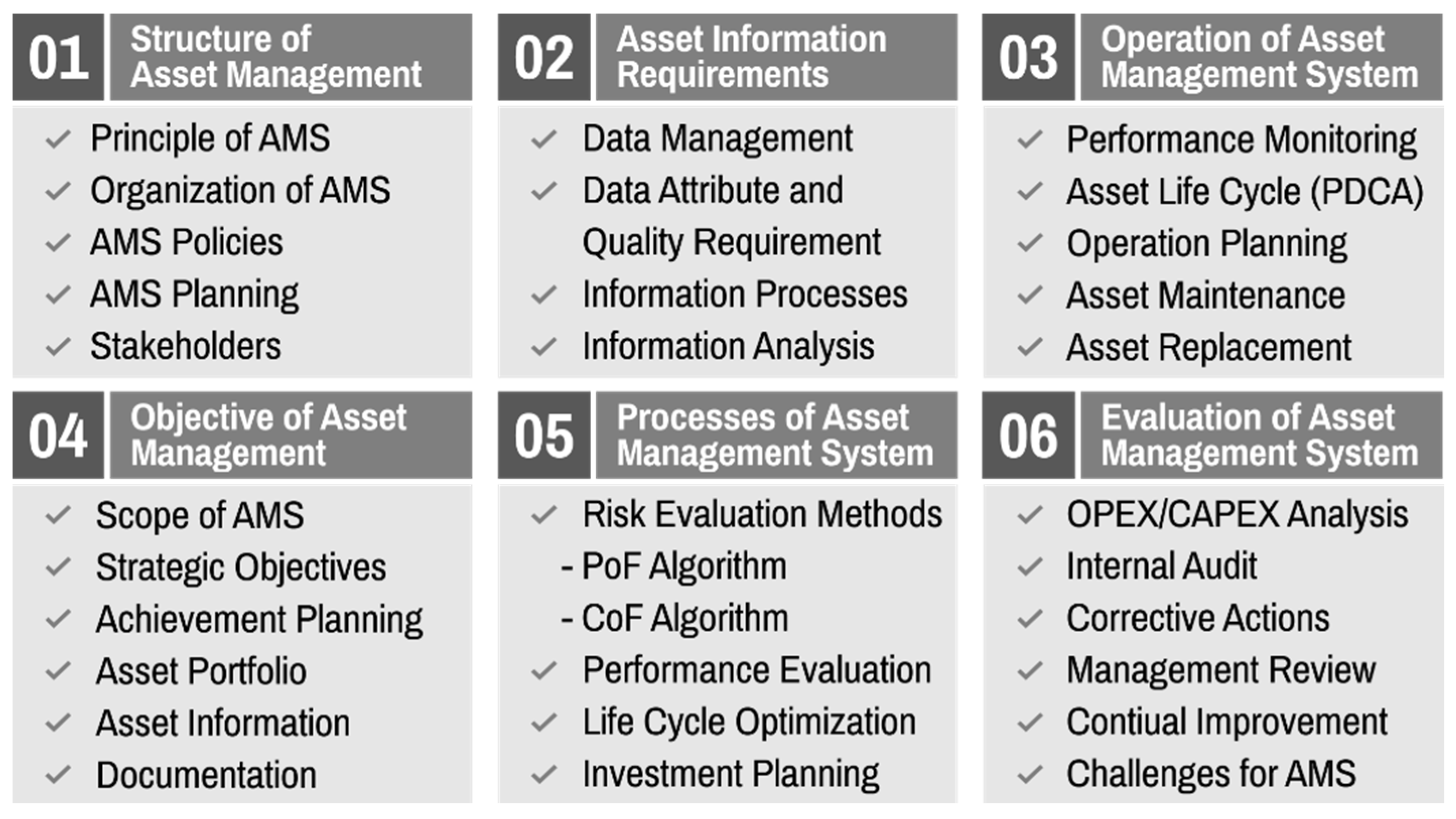
4]. The requirements and processes for asset management are composed of six steps: (1) the structure of asset management, (2) the objective of asset management, (3) asset information requirements, (4) processes of the asset management system, (5) operation of the asset management system, and (6) evaluation of the asset management system, as shown in Figure 1.
In this process, the technology gap depends on the asset data quality and the accuracy of the risk assessment algorithms for the power equipment. An AMS supports investment decision-making by evaluating the risk of every asset and prioritizing the replacement ranking [
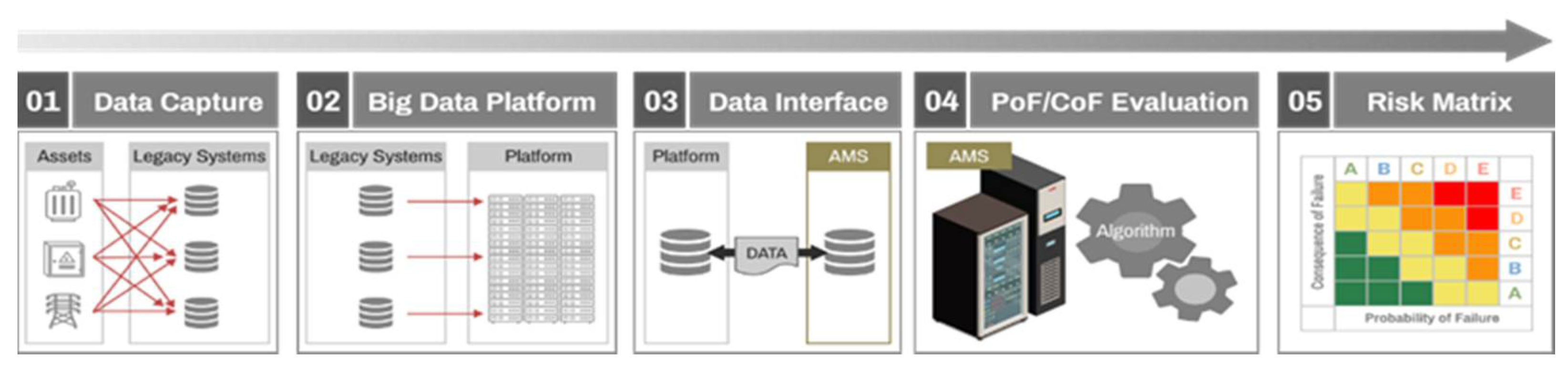
5]. The risk assessment algorithm is processed using asset data from legacy systems [6,7]. Currently, asset specifications, inspection and diagnosis, and operation information of power equipment are captured in various legacy systems and stored in a big data platform. Asset datasets in big data platforms can interface with asset management systems and utilize the risk assessment process shown in Figure 2.
AMS can be described as the life cycle management of physical assets considering the business needs [8]. For making decisions based on the life cycle of physical assets, it is mainly used to manage various electric devices in conjunction with IoT, which is related to the smart factory and healthcare industries [8]. A power system, which consists of extremely expensive assets, such as power generators, power transformers, and transmission lines, has been broadly renowned for being a capital-intensive industry [9]. The power outages, even as short as few seconds, cause a huge ripple effect to economic loss and human life. The fact that most power assets operate outdoors can be a challenge because they can be affected by weather, harsh ambient conditions [9]. In addition, it is difficult to find out the failure mechanism, because the long lifespan of the power asset makes it difficult to obtain the data from faulty asset with aging. Machine learning (ML) approaches, including supervised, unsupervised, or reinforcement learning have been studied and developed in power systems [9,10]. Among power assets including synchronous generator and power transformer, protection of transmission line plays a key role in the power system not only to minimize the equipment damage but also maximize the power grid reliability. Various research projects are being conducted in the field of protection among AMS [9,10]. Conventional protection algorithms are mainly developed to localize the fault based on the measured waveforms, including local voltage, local current, and impedance [9,10]. The most widely used signal processing methods to extract the features for fault identification are Discrete Wavelet Transform [11], S-transform [12] and Mathematical morphology [13]. Most used fault classification techniques are ANN [14], Fuzzy Inference System [15], and SVM [16]. Most of the previous studies in which AMS is applied to transmission system are fault detection algorithms based on real-time data acquired from sensors, and a system that integrates and manages all data of transmission system including real-time data is proposed for the first time in this paper.
Legacy systems are maintained and linked to each other, but data quality has not been fully estimated and managed. At the initial stage, there are no sustainable data cleaning tools, and the data quality does not generally satisfy the target value. If the legacy data are not reliable, then the results of the risk assessment algorithm could be inaccurate [17]. As a result, the priorities for replacement may differ, and investment plans may be incorrectly established. Therefore, legacy data quality is very important, which leads directly to the reliability of the asset management system [18,19]. Most companies agree that data are the most strategic asset [20]. Management of asset data quality is essential for operating the asset management system, but it has been reported that data scientists spend 60% of their time in cleaning and organizing data [21]. Thus, data cleaning and organization tools are required to increase the asset data quality and the reliability of an asset management system.
From classic data cleaning methodologies, it is well known that the data have essential characteristics, including accuracy, completeness, consistency, validity, timeliness, and uniqueness. In practice, various concerns are required including how the normal and dirty data could be classified, how we can clean those dirty data automatically, how we verify the cleaning results, and so on. Data cleaning works are being carried out in various industrial fields, but there is a property that the cleaning algorithm of a specific field cannot be directly applied to other fields. For this reason, it is essential to develop a cleaning algorithm specialized in the electric power field. To deal with missing and outlier data, data cleaning algorithms based on rule-based and domain knowledge have been mainly adopted and utilized [21,22,23]. In case of missing data, the missing data are replaced with average values, most frequent values, or median values. For the outlier data detection, outlier data are classified by checking whether they exceed the first or third quartile value. Here, the first and third quartile are values corresponding to the bottom 25% and top 25% of all data. Recently, artificial intelligence techniques have been investigated and applied to classify the normal and outlier data. For example, support vector machine (SVM) have been adopted for detecting the outliers injected into the measurement data from a power grid [23]. In another paper, the classic k-nearest neighbor (KNN) technique has been used for identifying the outliers [24].
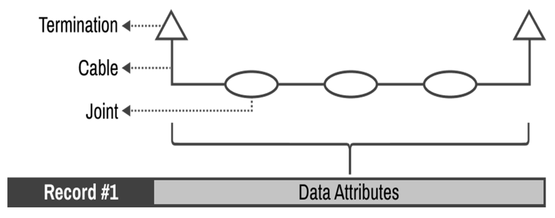
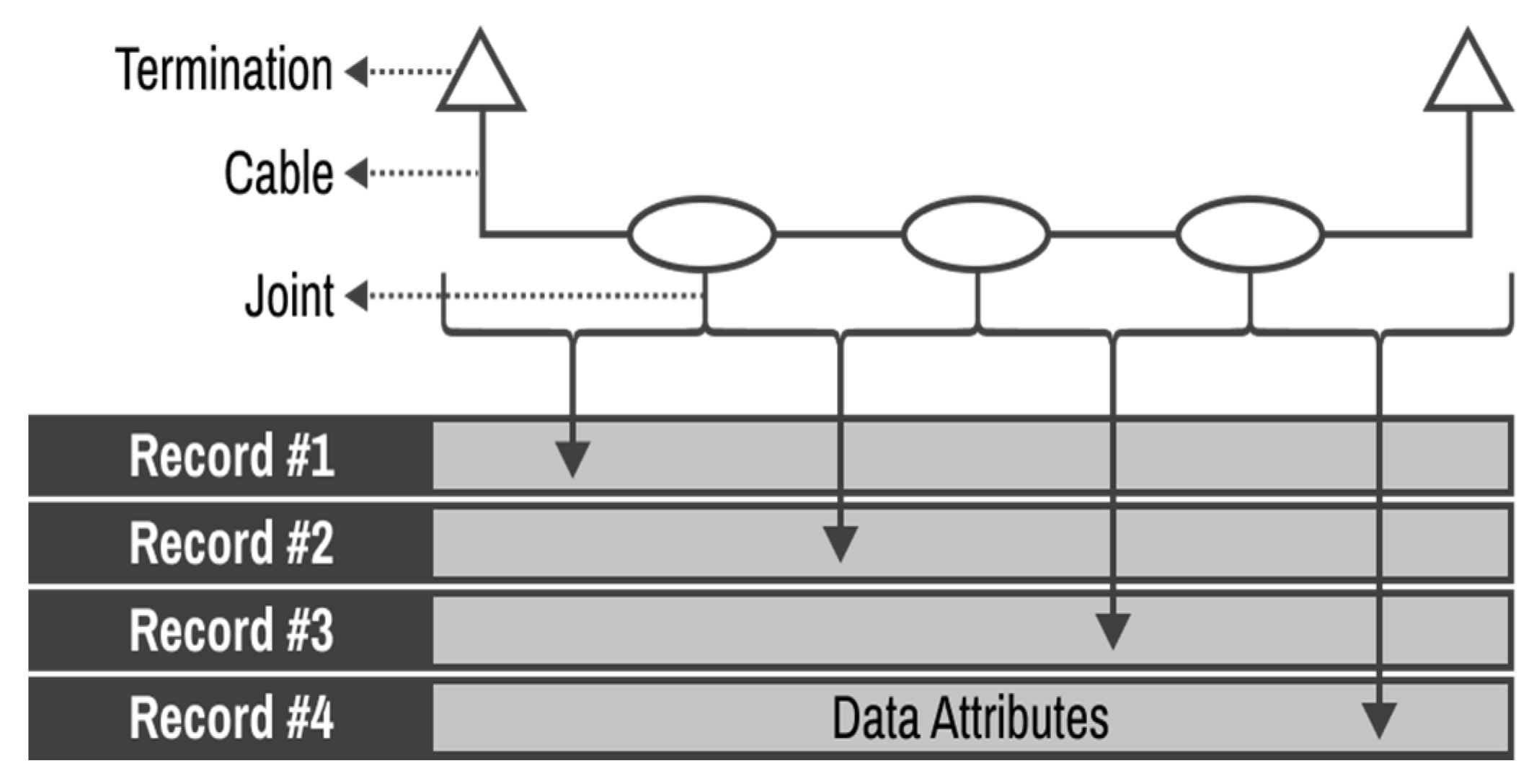
Numerical data measured in real time through sensors can be cleaned through ML approaches using the training data, but in the case of power systems, there is a lot of unique data, such as installation date, manufacturer, etc. For example, unique data of an asset, such as keycode, are difficult to clean, because there is no training data for the asset. For this reason, a customized cleaning method based on domain knowledge is required. In particular, the AMS applied to transmission line from the above point of view is a basic stage, and building a practical system based on real data rather than an academic dataset is proposed for the first time in this paper. The target data in this paper are acquired from three different legacy system, and there are 138 types. There is no system yet for cleaning such a vast amount of data types in transmission systems. The data of the transmission system are simply stored by each legacy system and are not integrated and managed. Therefore, it is more urgent to establish an integrated data management system than to develop an algorithm related to failure prediction.
Complying with the needs, each country’s power system operator is building the AMS suitable for each situation. The proposed AMS system can be divided into three systems: (1) data cleaning, integration, and quality check system, (2) data-based statistical method/ML approaches to extract key factors affecting the life of an asset and predict its lifespan, and (3) replacement timing selection system considering the ripple effect and economic value of assets in case of failure. The data cleaning, integration and evaluation system proposed in this paper is a part of the AMS to be applied to all power transmission systems in South Korea.
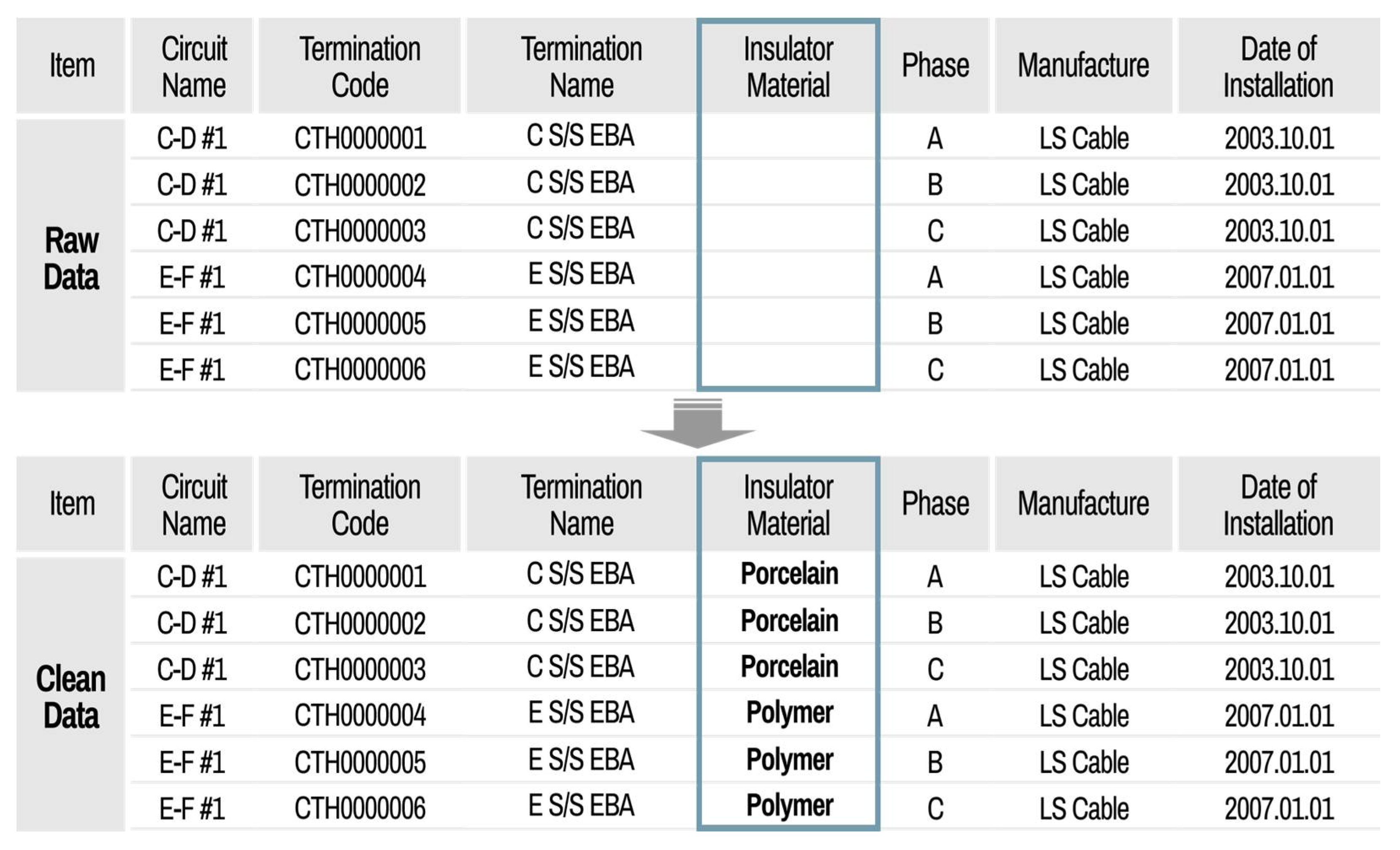
This paper proposes a new asset basic unit of asset for ease of data management. Based on data analysis obtained from 138 data types of three legacy systems, six types of suitable cleaning functions, three types of data integration functions, and data quality evaluation functions are introduced. In addition, the dirty data are automatically cleaned first, and only the dirty data, index, and the results of the cleaning function are sent to the relevant data managers for review. The data verified by experts are integrated with the original data using the index. In particular, through the data quality evaluation function of 15 divisions, each division is promoted to compete well in data management. The accuracy of the proposed algorithm is verified by comparing the automatically cleaned data with the real data instead of comparative analysis with other methods. In addition, we verify the performance of the proposed method based on the analysis results with different risk matrix results before and after using the proposed method. In future works, it is possible to develop an AMS considering installation location and manufacturer, etc., rather than the conventional AMS based on only sensor measurement data. This paper introduces the asset data management algorithm of South Korea’s power transmission system, and it is hoped that it will help other countries to build a system suitable for each country’s electric power system characteristics.
In Section 2, the data characteristics of linear assets are covered, a method for setting the basic unit of assets that make up the power transmission cable system is introduced, and a method for integrating data acquired from each legacy system is developed. Oil- filled (OF) and cross-linked polyethylene (XLPE) cables are considered only for our data cleaning, which are representative cable types in South Korea. As the type of assets that make up the system are diverse and affect each other, we propose a data processing method that takes this consideration into account according to the type of asset connected. To evaluate asset risk, it is necessary to clean the raw data collected by each legacy system. The data cleaning process can be divided into two steps. The first step determines whether the data contain outliers. Here, an outlier is a data point that differs significantly from other observations. This is accomplished using data pattern analysis or expert opinions. By default, data outside the 95% confidence interval are automatically classified as an outlier, but the system operator can manually set the outliers by inputting the boundary value of the probability distribution function derived based on the acquired data. In step 2, the outliers are extracted and delivered to the user for correction. For the case of data that can be automatically cleaned based on pattern analysis, the cleaning details and index are reported to the user to manage each legacy system after automatic data cleaning. Through pattern analysis, the outlier boundary value of each data point is determined according to the data type.
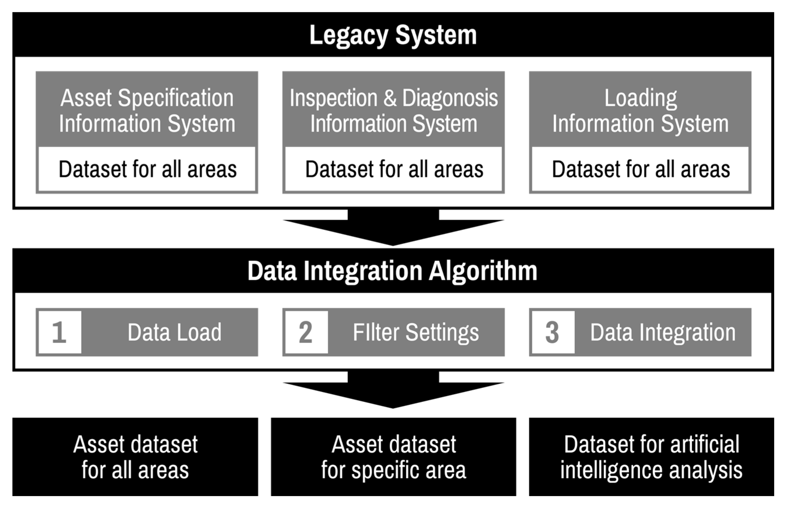
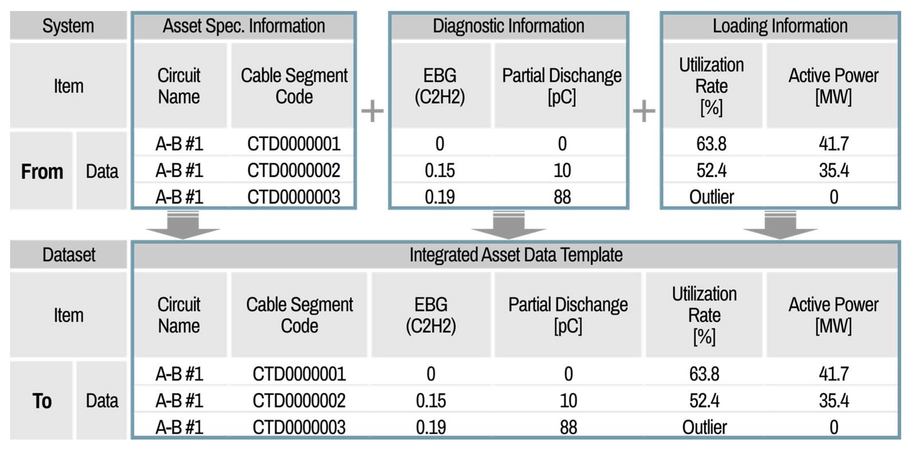
Section 3 describes the development of the data integration system. An integrated dataset from various legacy systems on a basis asset unit is necessary for simulating or processing a risk assessment algorithm. In addition, the process of integrating clean data verified by experts into the data is required. For this reason, an asset data integration algorithm has been developed as described in Section 4. The main features of the integration algorithm are an integrated dataset with user-friendly filter settings from the distributed legacy data, and output data that can be automatically obtained with guaranteed data quality.
In Section 5, a developed automatic legacy data cleaning and integration system utilizing these algorithms is described and verified using actual transmission cable data from South Korea. By comparing the risk matrix results before and after using the proposed algorithm, we can confirm the advantages of the developed system. In particular, the system can provide both cleaning and integration functions simultaneously and can be utilized sustainably for practical application cases of electric power utility.

2. Dataset of Transmission Cable System

Linear assets refer to a linear structure arranged in a row, with the components connected to each other serially. Cable and voltage types of our transmission systems are 154 kV, 345 kV and OF, XLPE. The cable system can be broadly classified into cables, joints, and terminations. All related data are collected from legacy systems. To evaluate the risk of each asset, the actual asset and failure data for each component are needed. Because the properties of the linear assets affect each other, they also affect the connected segments, even if a failure occurs in one segment of the entire circuit. To reflect these properties, we set the basic linear asset unit as one cable segment and the joint box on both sides.

2.1. Data Characteristic of Linear Assets

The characteristics of linear assets are that the circuit length and segment exist in the asset, and that these assets are installed under different environmental conditions [25]. In addition, when a failure occurs, the repair or replacement management method is used for each segment rather than for the entire circuit. In addition, the asset information characteristics, such as age, cable type, and installation environment, may be different for each segment. Because the unit of a linear asset is a segment, and not the entire circuit, the asset data for each section need to be collected and managed. If data management is not performed for each section of the circuit, but for the entire circuit, as shown in Figure 3, there are disadvantages in terms of capital expenditure reduction. For example, when the asset performance of a part of the circuit is poor and needs to be replaced, some cable segments may be replaced despite their excellent performances. In contrast, this paper proposes the method of inputting one record as a segment, as shown in Figure 4. Although this may complicate the data management because the entire data size could be much increased compared to when the unit of linear asset is a circuit, it has an advantage to determine which part of the cable section should be replaced instead of entire circuit through an accurate evaluation of each cable segment. The economic/time loss wasted in replacing the entire circuit instead of the faulty section is overwhelmingly greater than the cost of managing the increased data size. In addition, if information is collected on a circuit basis, then when a segment of a circuit is replaced, the data in the remaining segments may collide with the data of the new one (e.g., installation date). For this reason, IDs are required for data integration acquired from each legacy system; however, there are many cases in which ID data are damaged, or raw data are contaminated. Therefore, linear assets, such as cables and lines, follow the data input and management method described subsequently.

2.2. Legacy Systems Related to Cable Systems

For information systems of transmission cables, asset specifications, diagnosis, and loading data are collected from legacy systems. They are interfaced to each other using key ID. The information system for asset specification manages the history of the overall transmission assets, from data creation to destruction, based on geographic information. Representative data include cable type, circuit length, manufacturer, date of installation, etc. It is possible to identify the unique characteristics of an asset that does not change over time using this information. In the case of information systems for asset inspection and diagnosis results, data from an annual inspection or special diagnosis are recorded and managed. This system is interfaced with an information system for asset specification.
Representative data include diagnosis results of partial discharge, dissolved gas analysis (DGA) in insulating oil, and thermal hot spots. The inspection and diagnostic information system consists of three types of cable diagnostic data and three types of joint box diagnostic data, depending on the subject. Through the diagnostic information, the health status of the power equipment can be monitored. For loading information, various parameters, such as voltage, current, active power, reactive power, and utilization rate of cables, are recorded and managed. Through the loading information, it is possible to infer the degree of fatigue added to the power equipment in operation.

3. Automatic Data Cleaning Algorithm

All raw data generated in each legacy system are linked to the asset management system, and the risk assessment algorithm operates using the dataset. This implies that the data quality could affect the result of the algorithm, and this result directly connects to the investment strategy. Therefore, it is necessary to secure a high-quality dataset for the overall reliability of the system.

3.1. Role of Data Cleaning

Data preprocessing is widely known to consist of data collection, inspection, cleaning, verification, and reporting. As the number of assets increases, the cleaning time increases proportionately. Thus, it is very difficult to visually check and clean hundreds of thousands to millions of data by manpower. As the data cleaning takes a long time, it reduces work efficiency. Unfortunately, data are continuously accumulated over time, even though previous data cleaning has been performed. Incorrect data may occur owing to human error, which is caused by the manual input of asset specifications or inspection and diagnosis of data. To prevent time consumption, wastage, and additional errors that can occur during manual cleaning, the cleaning process should be automated to improve data quality. Experts with domain knowledge can determine whether the generated data are accurate or inaccurate. In addition, the diagnostic data could be classified as normal or outlier data by the corresponding experts. Therefore, data cleaners should understand the characteristics of the asset for data cleaning, and an automatic cleaning algorithm that combines rule-based and expert opinions is essential for constructing an asset dataset of high quality [25].

3.2. Data Cleaning Algorithm

The data cleaning method for power utilities with different types of assets has little information, and there is no ideal data cleaning tool for the assets. Hence, there is a need to develop a data cleaning system equipped with a cleaning algorithm. Data cleaning work includes collection of data, detection of missing data, and classification of outlier data. Based on analyzing the types of dirty patterns, we have proposed six types of cleaning setting functions that fit for each case, such as (1) transform, (2) pattern, (3) scanning, (4) historical, (5) criteria, and (6) calculation functions [26].
These settings support the classification of missing and outlier data, and cleaning. The six kinds of cleaning algorithms may operate independently, or two and three may be applied together at the same time according to data attributes. Various cleaning functions are introduced to explain the algorithm in detail, and some examples of transmission cable system assets are described in the following sections.

3.2.1. Transform Functions

The transform function is used to convert data after checking the distribution of the data. This function follows a rule-based cleaning method, which can be applied to asset specification information, where the correct answer is already determined. In particular, it can be used for unified circuit names or manufacturer names. The circuit name should be unified according to the specified internal guidelines, but data with misinformation could occur if they were typed by a person in legacy systems. As a solution, “A-B T/L” connecting substation A to substation B could be rule-based and cleaned by following the transmitting and receiving substation names. In the case of cable manufacturers, it is often hand-typed. As a result, the same name may have different names according to individual opinions. Figure 5 shows a representative example, where “LS Cable, LG Cable, LS Cable System, and LG Cable System” are cleaned to a unique name, “LS Cable”.

3.2.2. Pattern Functions

The pattern function checks the data pattern and detects the outlier data. The electric power equipment follows a three-phase system consisting of A, B, and C phases. The numbers of A, B and C phases should always be the same. However, if the data of phases are hand-typed into the legacy system, the number of phases may not be identical. Originally, it was normal to input A, B, and C phases in order, but the number of phases did not match each other owing to human error. For example, “A, B, and B phase” or “A, B, and missing” could be automatically cleaned to “A, B, and C phase” using the pattern function after checking that the rest of the information is consistent with the information on the other phases. The pattern function can also be applied in the case of single-circuit (S) and double-circuit (D1 and D2) information. When a large amount of transmission capacity is required between substations A and B, double cables are installed instead of a single cable. In this case, the double cables are divided into D1 and D2. Because D1 and D2 form a group, the numbers of D1 and D2 should be the same. “D1, D2, D1, D2, D1, D2” information needs to be checked, considering that the phase information “A, A, B, B, C, C” occurs together. For example, “D1, D2, D1, D2, D1, missing” could be cleaned to “D1, D2, D1, D2, D1, D2” through a pattern function, as shown in Figure 6. As an additional example, the pattern function is also used for outlier classification that the total circuit length should be equal to the sum of the lengths of each cable segment.

3.2.3. Scanning Functions

The scanning function detects outlier data by checking the uniqueness of the data. The keycode of equipment for circuit names is automatically generated as a circuit code number and is assigned when the asset data are created for data linkage in the legacy system. However, in a few cases, two or more keycodes of an asset are generated because of data redundancy. The best way to detect this outlier problem is to check by counting the number of keycodes assigned to one circuit name, as shown in Figure 7.
If keycode data are not managed, then without cleaning, one circuit can be seen as two circuits in the back end. Therefore, the scanning function can classify the outlier data in which the keycode is duplicated in one circuit name. The duplicated keycode can then be revised as a unique keycode after confirmation of legacy system operators.

3.2.4. Historical Functions

The historical function applies historical information when the content of the data attribute is entirely missing or needs to be replaced as of the base date. First, the base date is checked to determine when the new equipment type was previously applied. Next, the previous type data are input from the past to before one year of historical changing time. The current type data are then input from after one year of historical changing time. The data setting −1 and +1 year based on the base date is intentionally omitted to check from legacy system operators. Finally, the missing data can be filled after an on-site check. For example, if cable termination insulators were changed from porcelain to polymer material on 1 April 2005, then the data can be automatically input for porcelain insulators from the past to 31 March 2004, and for polymer insulators from 1 April 2006 to now, as shown in Figure 8. Only the missing data between these periods can be efficiently cleaned.

3.2.5. Criteria Functions

The historical function applies historical information when the content of the data attribute is entirely missing or needs to be replaced as of the base date. First, the base date is checked from the diagnostic dataset. The date of cable installation is used for age information; therefore, it is important for asset management. By hand typing the input method to the legacy system, some date information for a calendar method may be interpreted as outlier data. For example, one cable was installed on 1 January 2012 (yyyy-mm-dd: 2012-01-01); however, real data were obtained from 0212-01-01. In this case, the real age of the cable is nine years old, but the data are 1809 years old. Because of the outlier data, a nine-year-old circuit could be replaced based on the data.
By scattering the entire date points and the criteria of the top and bottom lines set by the cleaner, values outside the set range are marked as outlier data. Another example of the criteria function is the thermal inspection of cables and joint boxes. The maximum temperature was measured on-site using a thermal imaging camera, and the measurement data were uploaded. The measured temperature was 22 °C, but 222 °C was incorrectly input to the legacy system. In this case, the criteria function considering the appropriate temperature range could be used to extract outlier data from the entire dataset, as shown in Figure 9. Although it is difficult to have a 222 °C value, if the 222 °C value is used for the risk assessment algorithm, then the output will show a dramatic difference. Hence, the outlier data were extracted and cleaned.
An example of a complex usage of a cleaning function is about each cable segment length. First, the criteria function is utilized for the length of each cable segment. The segment length data different from rule-based standard are classified as outlier data. In addition, the pattern function is also used for outlier classification that the total circuit should be equal to the sum of the lengths of each cable segment as mentioned in Section 3.2.2.

3.2.6. Calculation Functions

The calculation function calculates the utilization rate using the active/reactive power of the circuit. The utilization rate information, which can be calculated using the load information, is important for estimating the remaining lifetime in future study. One of the problems is that there are missing data on the utilization rate despite the presence of information. In this case, the utilization rate data can be calculated using active/reactive power information, as follows (1):
U r a t e = P 2 + Q 2 3 V I 100
where U r a t e , which is a utilization rate, can be derived using the calculation function based on active power, P [ W ] , reactive power, Q [ V A R ] and rated voltage, V [ V ] stored in the load information legacy system; and ampacity, I [ A ] stored in the information system for asset specification, respectively.

4. Automatic Data Integration Algorithm

To implement the risk assessment algorithm for the asset management of electric power equipment, the distributed data of various legacy systems must be integrated into one dataset.
In addition, the data confirmed by the system manager after being cleaned by the automatic data cleaning algorithm should be overwritten in place of the dirty data for the entire dataset. The integrated dataset is stored in an asset data template file, as shown in Figure 10, and this file can support the risk assessment and replacement priority simulation for target assets and be used for various purposes.

4.1. Role of Data Integration

If there is no automatic integration tool, then integration work must be performed manually. Some columns of the collected data require a copy and paste to the columns of the integrated file. Others can convert, calculate, or link together using keycodes. These tasks are inconvenient and time-consuming when performed manually.
In addition, data are continuously generated over time; therefore, the integration work must be carried out again. Unfortunately, there is no related information system for specific power utility assets; thus, an automatic data integration algorithm is required to reduce the burden of integration tasks. This technique can be used in various ways, including big data analysis using artificial intelligence, in addition to risk assessment simulation.

4.2. Data Integration Algorithm

Data integration work includes collecting data, setting the integration filter, and integrating the data. In the data integration algorithm, there are various integration filter settings, such as simple move, formula, and link function. These settings support various legacy datasets to be integrated into a single file efficiently and conveniently. This algorithm could significantly shorten the time from one month to within one day. As users can create the desired filter settings, this approach has the advantage of being customizable by user’s definition, and can output any result, such as integrated data for all areas, specific areas, or datasets for artificial intelligence analysis. Thus, it could be seen as a highly usable and user-friendly system in the era of the Fourth Industrial Revolution.
Various integration functions have been introduced to explain the algorithm in detail, and some examples of assets are described in the following sections.

4.2.1. Simple Move Functions

A simple move function is applied for copying and moving each column of the collected legacy data using the column of the data integration file. Although it is a very simple operation, a human error may occur if it has to be repeated a large number of times. If filter information is defined and operated in the system, then the conventional manual method can be improved by automation. It is possible to move various data attributes of each information system to an integrated asset dataset, as shown in Figure 11. This function, though quite simple, proves to be very powerful in reducing time and resources.

4.2.2. Formula Functions

The formula function is applied to move the columns of the legacy data to the columns of the integration data file using a defined formula. As shown in Figure 12, when the “Direct Buried” cable installation method is used, ambient temperature data can be input as 25 °C into the integrated data template. In the case of a tunnel, 40 °C can be filled in the integrated data template. Furthermore, to fill in the representative bonding system, cross-bonding or a single bonding method can be input based on the number of cable segments. When the number of cable segments is greater than three, the data can be cross-bonded. In other words, single bonding can be used as an input. As such, the formula function calculates or infers new data based on existing data.

4.2.3. Link Functions

The link function is applied to link the cable specifications and diagnosis data for one integration dataset. As mentioned above, these data are stored in different information systems. The desired column of the integrated file can be input by linking the columns of multiple collection files through the key value.
For example, as shown in Figure 13, if the results of the DGA of the OF cable are required to be input into the integrated data cable specification, diagnostic data points should be linked to each other using the equipment codes, which are the key values of the two datasets, and are integrated as one asset data template. If the type of cable is XLPE cable instead of OF cable, then the DGA data should not be connected as integrated data, because they are not related to DGA.

5. Development of Data Cleaning and Integration System

An automatic data cleaning and integration system for asset management was developed based on both cleaning and integration algorithms, as described in Section 3 and Section 4. In addition, other applications, such as data loading, data quality assessment, exporting clean and dirty datasets, and feedback, have been implemented in the same system. 
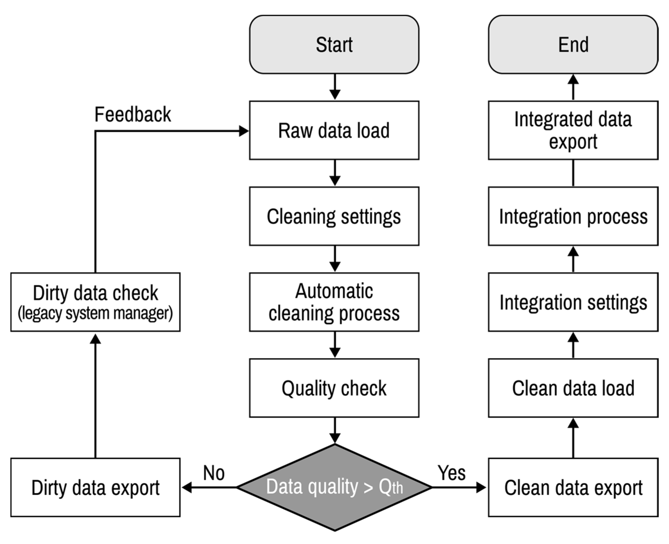
Figure 14 shows the entire process of automatic data cleaning and integration. The parameter Q t h is a threshold for data quality that is determined by the users. Data quality has a maximum limit depending on the degree of contamination and proportion of missing data. The real-time data measured through the sensors can be improved through the ML approach-based signal processing methods. However, among the data handled in this paper, unique data such as installation date, manufacturer, keycode of equipment, not real-time measurement data, have a practical limitation of data quality, because there are no training data. Therefore, the threshold of data quality is set as a system input value so that the user can determine the desired threshold based on degree of data contamination. Until the quality of the clean data after the automatic data cleaning process becomes higher than Q t h , the automatic data cleaning process is continued. Finally, the integrated asset data template file filled with integrated data can be obtained using a cleaned dataset. After the development of this system, it is demonstrated with legacy datasets utilized for the asset management of electric power equipment in South Korea.

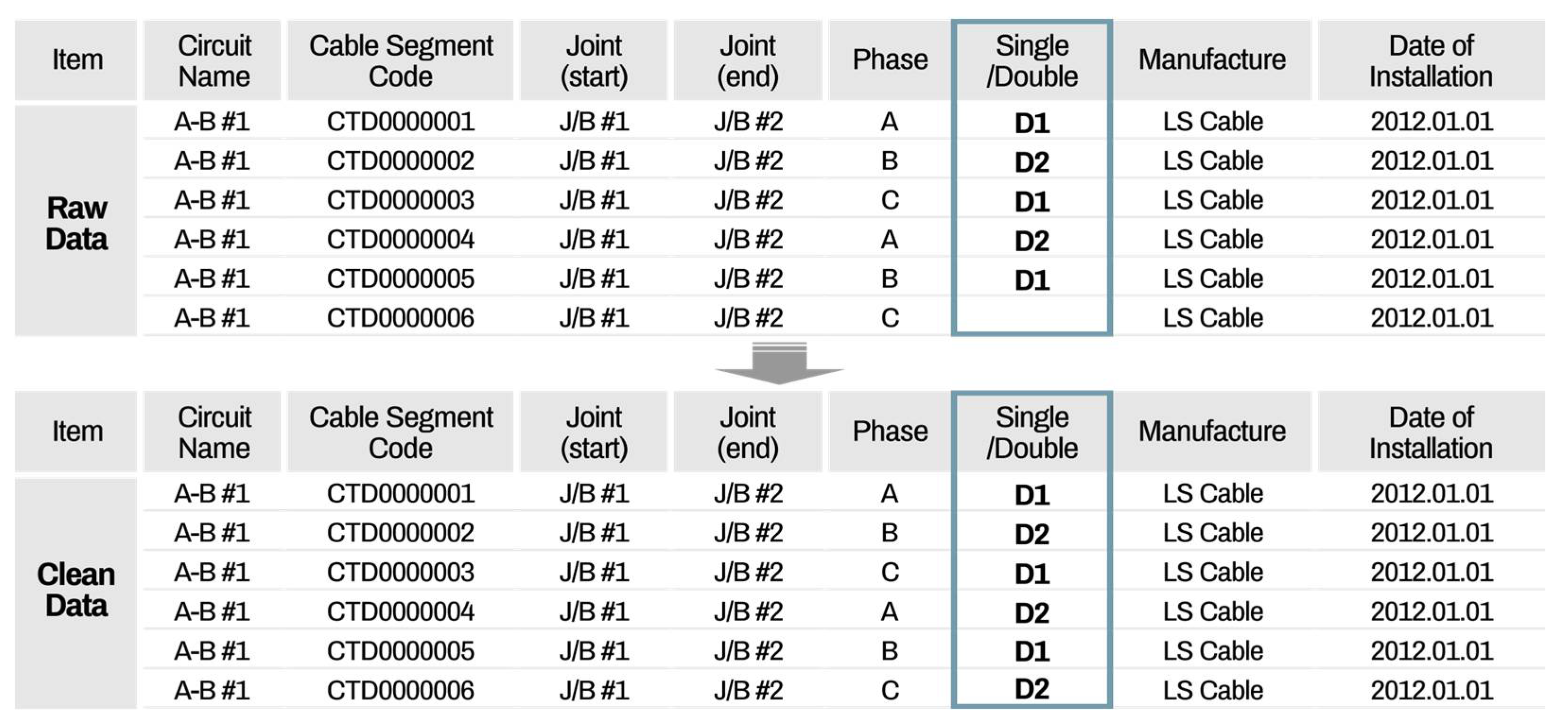
5.1. Detailed Functions of Data Cleaning Part

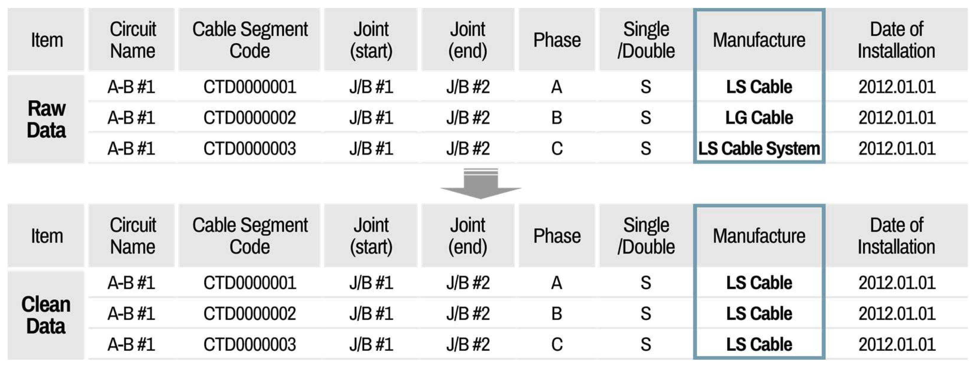
The main functions of the cleaning part include data cleaning, quality evaluation, and quality comparison analysis, before and after cleaning and exporting clean data. After loading all raw datasets from different information systems, a data cleaning setting is first implemented. The default mode, which is predefined by the system manager, can be set in the cleaning setting. If the user wants to have their own cleaning setting, then the properties can be revised by the user and saved as a file setting. This cleaning file setting can be imported at any time. When the default cleaning setting is set, the user can recognize the setting rules for each data attribute. For the manufacturer attribute, the transform function is applied. The present data status is shown in 
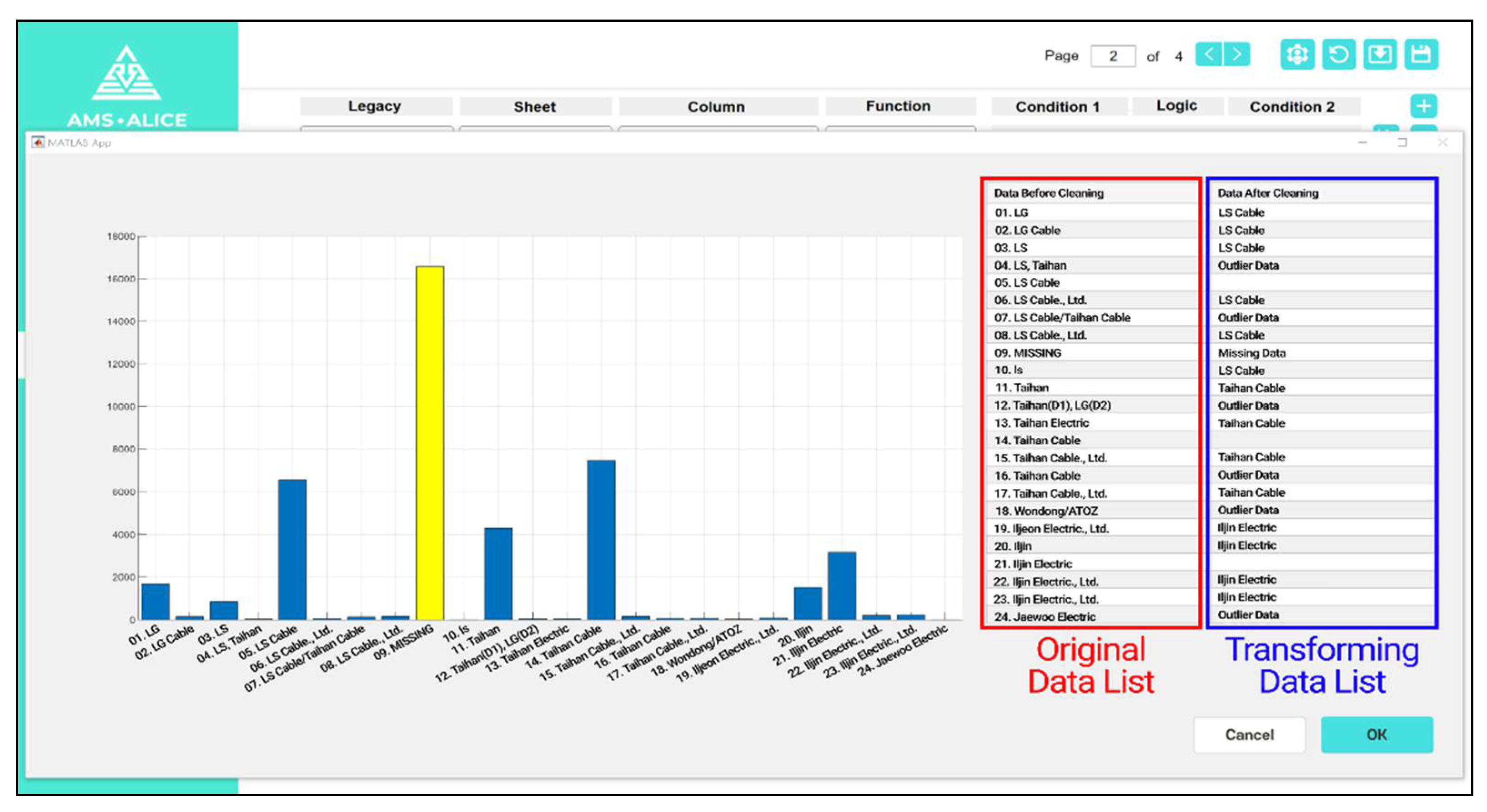
Figure 15, which illustrates an example of a data cleaning setting using a transform function.
Users can find the histogram chart, including the missing and outlier data, with the naked eye, and then, the cleaning setting can be determined. In Figure 15, the column displayed on the left indicates the type of data after reading the acquired file, and the column on the right is a location where the user writes the content to be transformed. The content in the original data list is automatically saved as it is transformed when the user enters the desired data in the transforming data list.
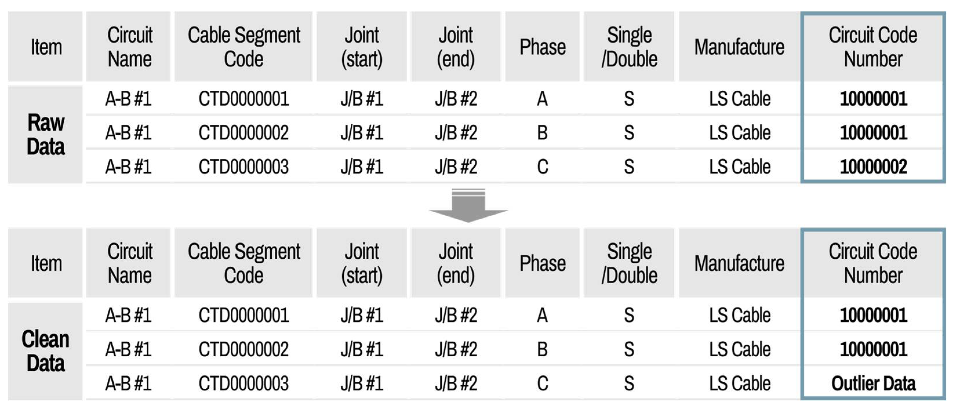
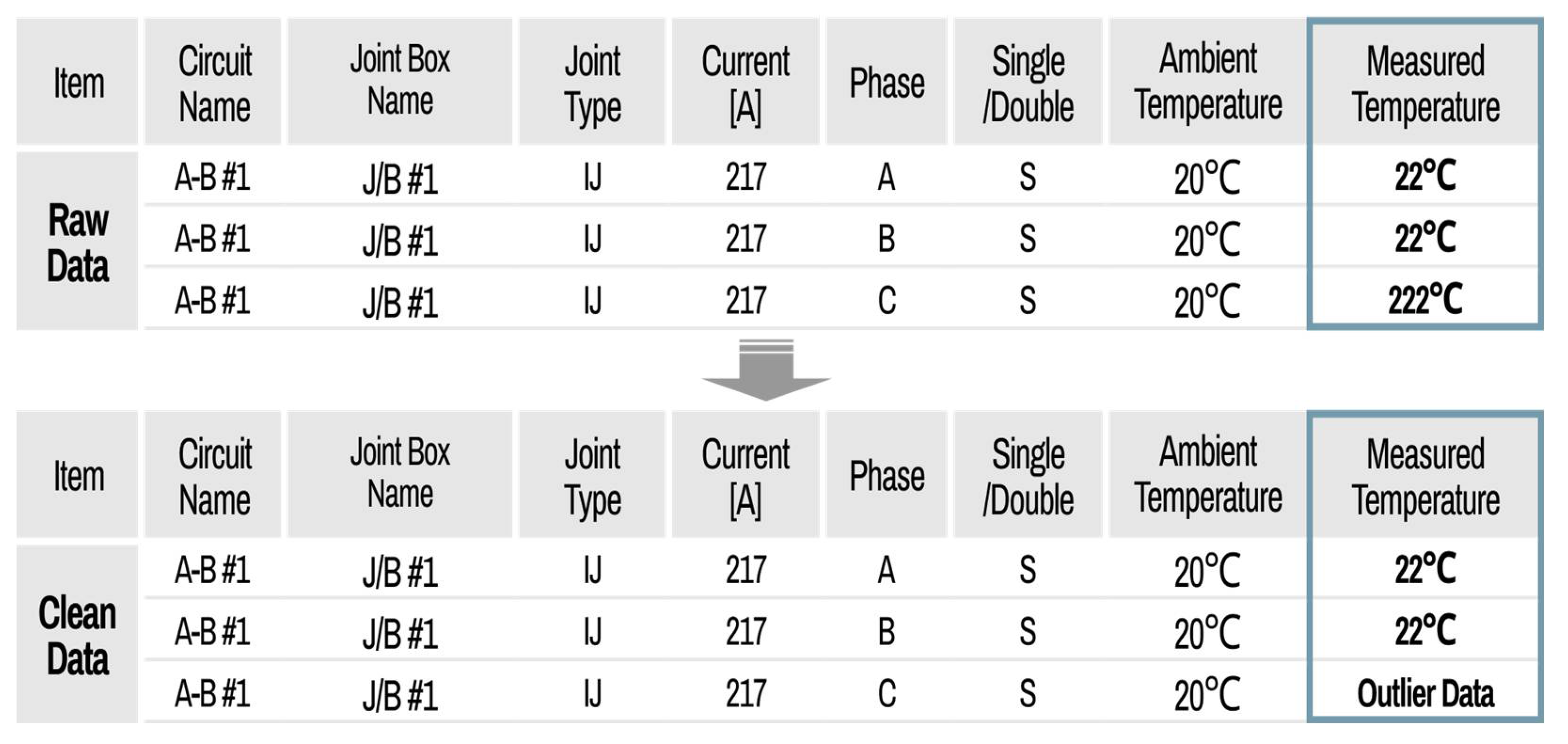
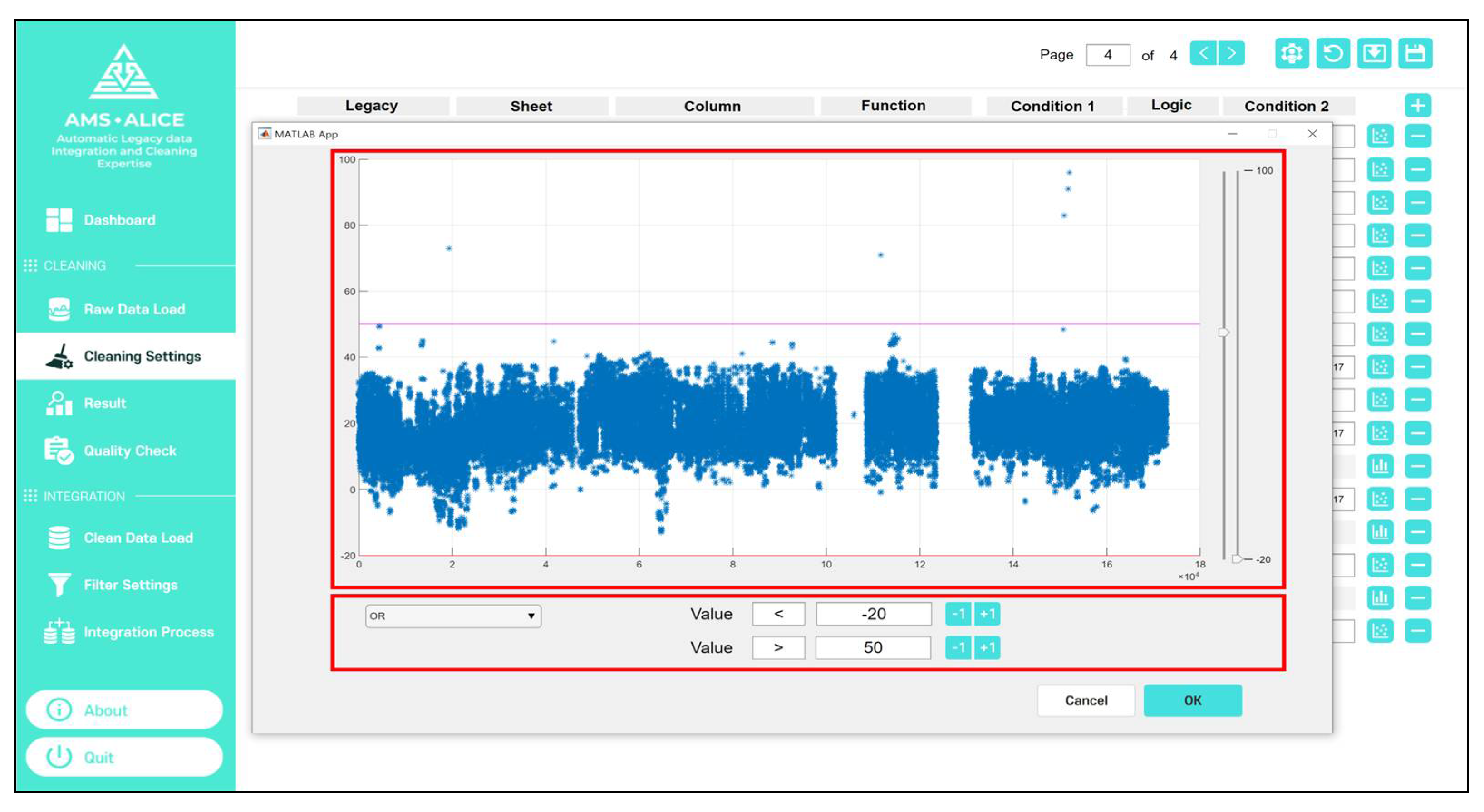
Figure 16 shows an example of a data cleaning setting using the criteria function. In the case of measurement data attributes for cable diagnosis, the criteria function is applied, and a scatter plot is used to define the boundary levels to distinguish the normal and outlier data. The data between boundary levels are recognized with normal data, and the other cases are outlier data.
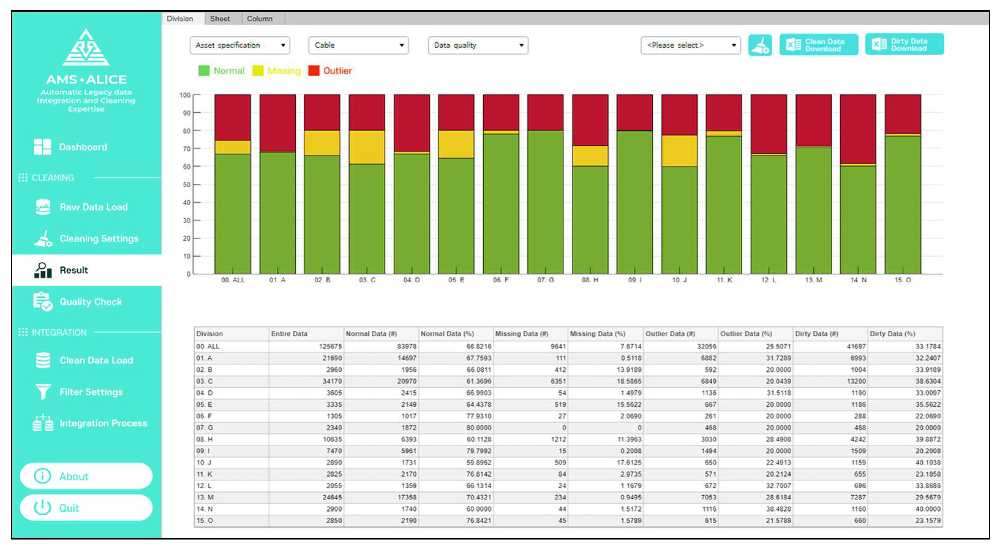
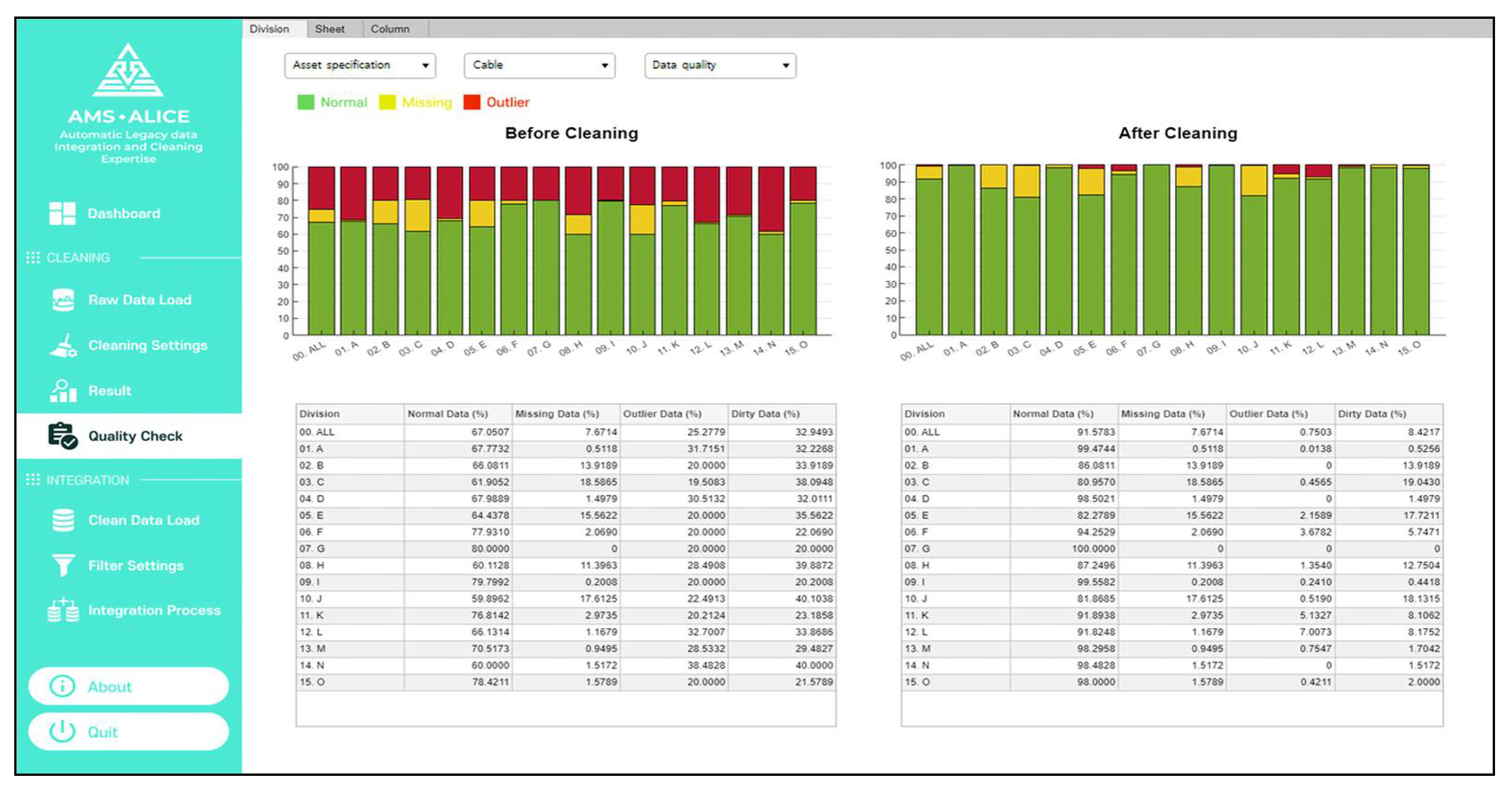
After the setting, the data quality is evaluated as a percentage by processing the cleaning. Visualized data quality checks according to the entire view, different divisions, and data attributes can be determined, as shown in Figure 17, where the percentages of normal data, missing data, and outliers are 68%, 8%, and 24% of the total data (green, yellow, and red bars, respectively). From the results of data quality, users can find the dirty data list and identify which data attribute should be cleaned quickly from an overall perspective.
To clean the data attribute, the dataset containing only the dirty data and index can be exported to a spreadsheet file. The user can clean the dirty data comprising missing and outlier data in the file. After loading the dirty data, the cleaned data is overwritten at the location of the dirty data among the entire dataset, and then, the cleaning process is repeated. In the quality check, the user can see the quantitative data accuracy changes before and after cleaning, as shown in Figure 18. If the data quality does not meet the user’s target specification, these processes can be repeated to improve the data accuracy.

5.2. Detailed Functions of Data Integration Part

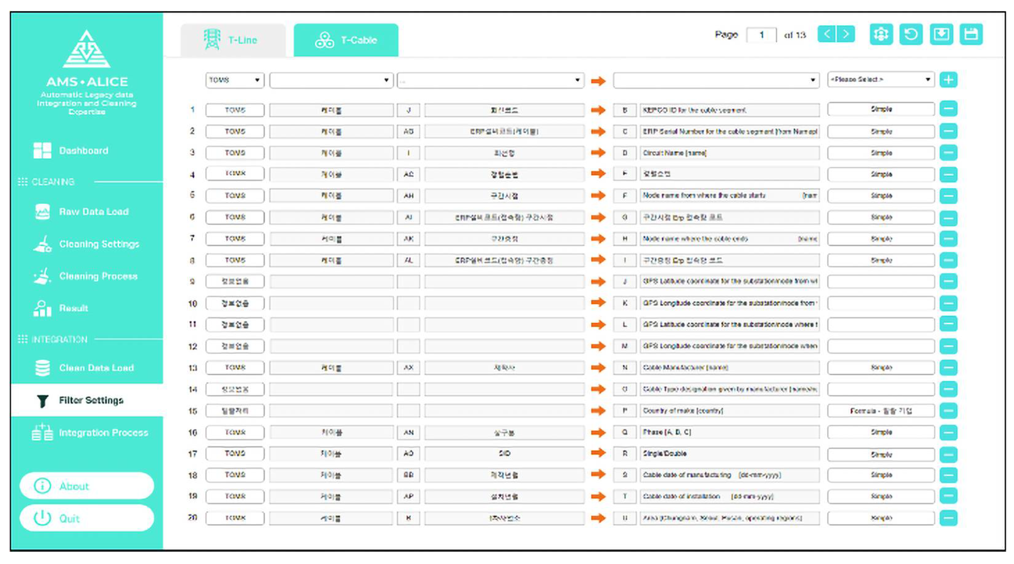
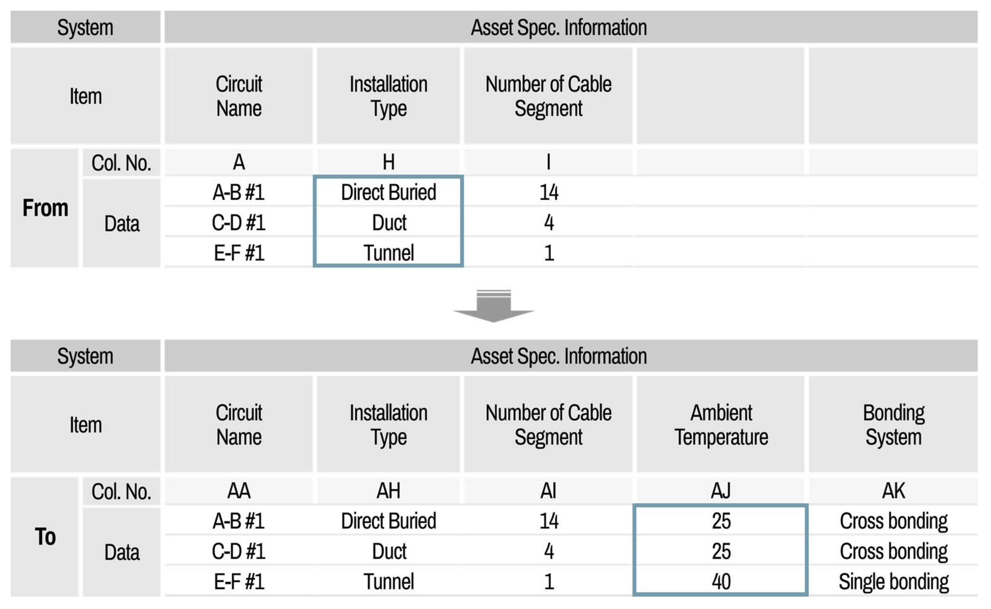
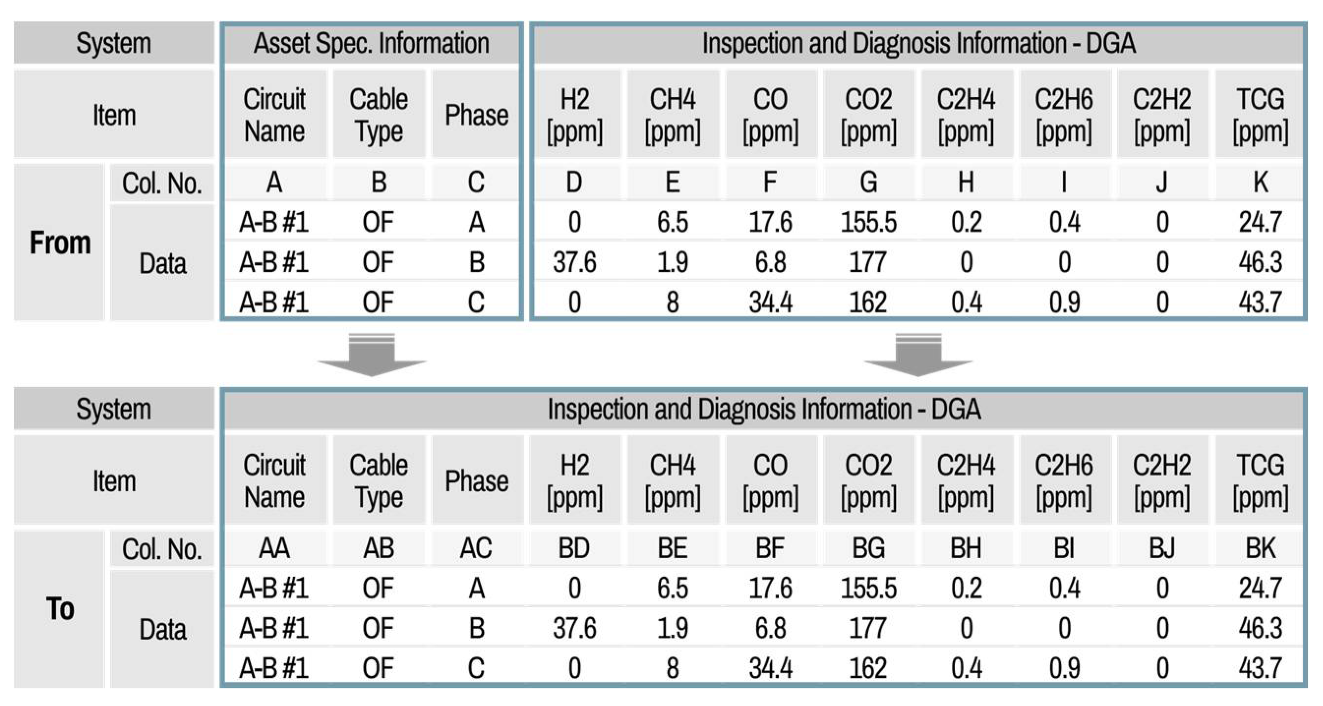
The main functions of the integration part include data filter setting, integration processing, and export of the asset data template. After loading all the clean datasets from different information systems, the filter setting is first carried out. Similar to the cleaning part, the default mode, which is predefined by the system manager, can be set in the filter setting. The filter setting has lists composed of left original data columns and right integration data columns, as shown in Figure 19; these are from–to the data list.
In this process, the user can select one filter among various filters, such as a simple move, formula, and link function. The user can check the detailed contents of the integration filters. If the user wants to have a customized integration filter setting, then the properties can be modified by the user and saved as a custom setting file. This filter setting file can be called up at any time. When the integration setting is ready, the data integration processes can be executed and exported as an integrated file of the asset data template.

5.3. Demonstration Experience

The advantage of the developed system is that it is possible to output various asset data templates according to the preset filter settings, and it is very efficient in saving time owing to the automation process. When these cleaning and integration tasks are done with automation, the turnaround time can be drastically reduced to within approximately one day, compared to the manual method, which takes several months.
This system has been demonstrated for cleaning and integration in the asset management of electric power equipment. From the demonstration results of data cleaning, the legacy data accuracy increased from approximately 70% to over 91% as seen in Figure 18. Because the cleaning data with average or regression values without the verification of a manager may lead to different results, it is difficult to clean it with only an automatic cleaning algorithm. For this reason, the legacy system manager has to manually check the cleaned data values derived by the automatic cleaning algorithm.
This system can reduce the turnaround time from several months to within a week. The processing time of these tasks depends on the cleaning time, and correcting the original data depends on on-site operators who need to confirm the data correction, as it is the responsibility of the department of equipment operation. For the case of integration tasks, the asset data templates for 15 area divisions have been integrated easily and quickly, and the turnaround time was reduced from several months to a day. In conclusion, this automatic legacy data cleaning and integration system, though simple, has very powerful functions in increasing the efficiency of data preparation for asset management.

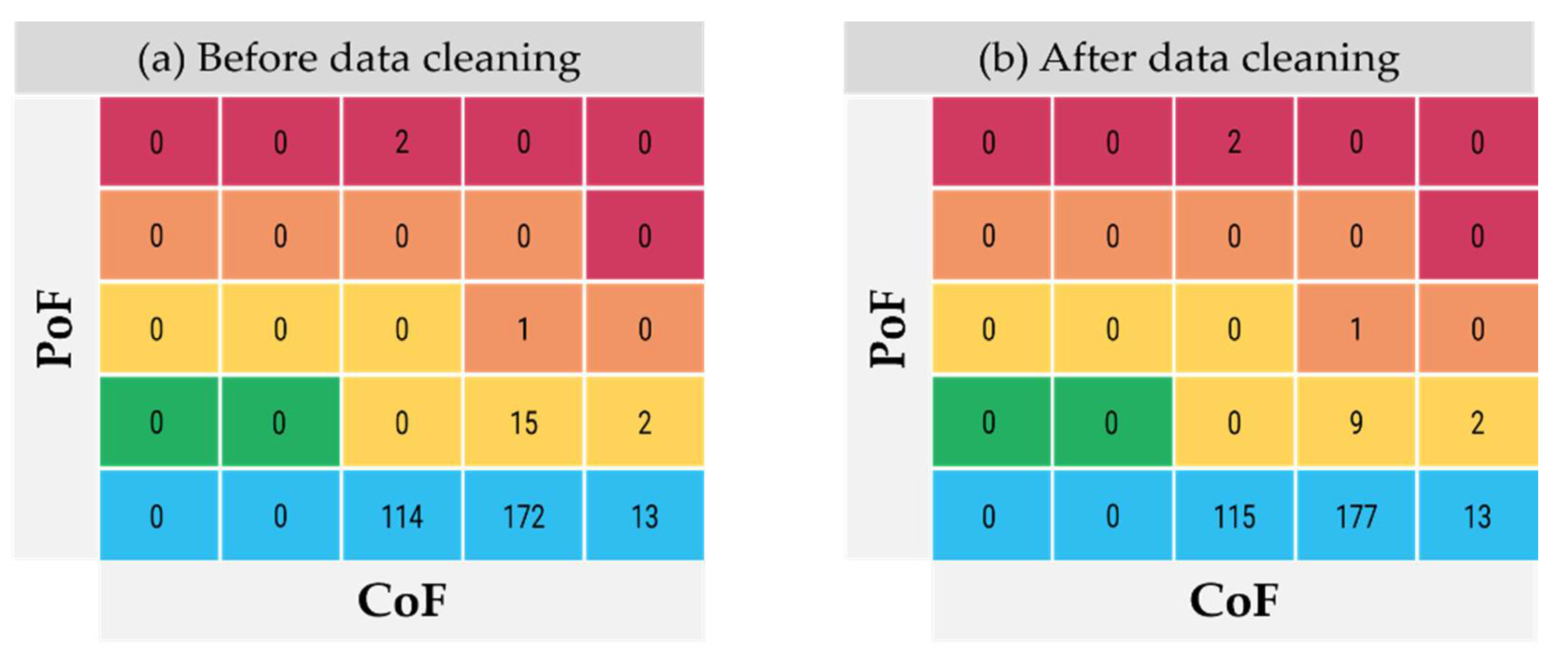
5.4. Data Cleaning Effects on Risk Matrix

In order to identify the effect of asset data cleaning on risk matrix, which consisted of PoF and CoF axis, the risk assessment algorithm was implemented for three divisions and the results of risk matrix before and after data cleaning are shown in Figure 20. The total number of cable circuits were the same between them but, the risk distribution is slightly different from each other. Especially, 6 of 15 circuits in the yellow area in the risk matrix before data cleaning were changed because the years of installation were cleaned from 1970 to 2013. In other cases, some data were changed but, the effect on risk matrix was not shown. However, these cleaned datasets contributed to approximately 14% reduction in the total risk value of all circuits. The risk value can be calculated based on a hazard function and probabilistic analysis, and the lower the number, the lower the risk of failure. Since the developed system is introduced to the evaluation of Korean power transmission system, the risk value calculation algorithm installed in the system cannot be disclosed. These results are interfaced to asset investment planning. For this reason, the investment planning could result in a different output.
Thus, data quality is essential, which leads directly to the reliability of the asset management system. From the development of cleaning algorithm and its system, the asset data quality has been secured and these reliable data could contribute to the asset management system for linear assets.

6. Conclusions

A novel data management system for managing data in the field of transmission cable systems was proposed, which includes auto cleaning, data integration, and evaluation functions. The data management system was divided into three parts: (1) data cleaning, (2) data integration, and (3) evaluation of data quality. The cable section and the joint box at both ends are considered as the basic asset unit. The cleaning part was proposed to consist of six functions according to the data characteristics, and the set values were modified by incorporating expert opinions. The cleaned data were sent to each legacy system, which collected data for feedback. The performance of the automatic cleaning algorithm gradually improved through feedback. After the cleaning process, the proposed integration algorithm consolidated the distributed and stored data in each legacy system based on each asset unit, which consisted of three functions depending on the usage. A system was built to evaluate the data quality for each system at each regional office, to evaluate the data quality before and after cleaning for actual power equipment data over all of South Korea, and to verify the performance of the proposed system through the feedback of the managers of each system. The proposed automatic cleaning algorithm can be applied to transmission cable system based on the knowledge of the power asset domain, has a limitation that it is difficult to apply directly to other fields. As data processing has inherent limitations in that it has to consider the characteristics of the target domain, in order to apply it to other fields, the proposed algorithm must be modified based on the knowledge of the relevant field. The proposed data management system in this study is expected to become a touchstone for the asset management system of electric power assets. AMS considering installation location and manufacturer, etc., rather than the conventional AMS based on only sensor measurement data can be developed based on this paper.

Author Contributions

Conceptualization, J.-S.H.; methodology, J.-S.H.; software, G.-W.O. and Y.-S.S.; validation, S.-D.M. and T.-J.K.; investigation, J.-S.H. and S.J.C.; writing—original draft preparation, J.-S.H. and S.J.C.; writing—review and editing, J.-S.H. and S.J.C.; supervision, S.J.C. All authors have read and agreed to the published version of the manuscript.

Funding

This research was supported by Korea Electric Power Corporation (Grant number: R20TA12).

Conflicts of Interest

The authors declare no conflict of interest.

References

  1. Ross, R. Reliability Analysis for Asset Management of Electric Power Grids; John Wiley and Sons Inc.: New York, NY, USA, 2019. [Google Scholar]
  2. McGranaghan, M. Making connections: Asset management and the smart grid. IEEE Power Energy Mag. 2010, 8, 16–22. [Google Scholar] [CrossRef]
  3. ISO 55000; Asset Management—Overview, Principles and Terminology. International Organization for Standardization: Geneva, Switzerland, 2014.
  4. ISO 55001; Asset Management—Management Systems—Requirements. International Organization for Standardization: Geneva, Switzerland, 2014.
  5. Vermeer, M.; Wetzer, J.; Van Der Wielen, P.; De Haan, E.; De Meulemeester, E.; Mischa, V. Asset-management decision-support modeling, using a health and risk model. In Proceedings of the 2015 IEEE Eindhoven PowerTech, Eindhoven, The Netherlands, 29 June–2 July 2015. [Google Scholar] [CrossRef]
  6. Middleton, B. The right data drives asset management decision making: A case study of delivering improvements. In Proceedings of the IET & IAM Asset Management Conference 2012, London, UK, 27–28 November 2012. [Google Scholar]
  7. McGrail, A.J. Asset management: Data and decisions. In Proceedings of the IEEE PES T&D Conference and Exposition, Orlando, FL, USA, 5–10 May 2012. [Google Scholar]
  8. Wang, M.; Tan, J.; Li, Y. Design and implementation of enterprise asset management system based on IOT technology. In Proceedings of the 2015 IEEE International Conference on Communication Software and Networks (ICCSN), Chengdu, China, 6–7 June 2015. [Google Scholar] [CrossRef]
  9. Aminifar, F.; Abedini, M.; Amraee, T.; Jafarian, P.; Samimi, M.H.; Shahidehpour, M. A review of power system protection and asset management with machine learning techniques. Energy Syst. 2021, 1–38. [Google Scholar] [CrossRef]
  10. Khuntia, S.R.; Rueda, J.L.; Bouwman, S.; van der Meijden, M.A.M.M. A literature survey on asset management in electrical power [transmission and distribution] system. Int. Trans. Electr. Energy Syst. 2016, 26, 2123–2133. [Google Scholar] [CrossRef] [Green Version]
  11. Zin, A.A.M.; Saini, M.; Mustafa, M.W.; Sultan, A.R.; Rahimuddin, R. New algorithm for detection and fault classification on parallel transmission line using DWT and BPNN based on Clarke’s transformation. Neurocomputing 2015, 168, 983–993. [Google Scholar] [CrossRef]
  12. Moravej, Z.; Pazoki, M.; Khederzadeh, M. New Pattern-Recognition Method for Fault Analysis in Transmission Line with UPFC. IEEE Trans. Power Deliv. 2015, 30, 1231–1242. [Google Scholar] [CrossRef]
  13. Godse, R.; Bhat, S. Mathematical Morphology-Based Feature-Extraction Technique for Detection and Classification of Faults on Power Transmission Line. IEEE Access 2020, 8, 38459–38471. [Google Scholar] [CrossRef]
  14. Abdullah, A. Ultrafast Transmission Line Fault Detection Using a DWT-Based ANN. IEEE Trans. Ind. Appl. 2018, 54, 1182–1193. [Google Scholar] [CrossRef]
  15. Pradhan, A.; Routray, A.; Pati, S. Wavelet Fuzzy Combined Approach for Fault Classification of a Series-Compensated Transmission Line. IEEE Trans. Power Deliv. 2004, 19, 1612–1618. [Google Scholar] [CrossRef]
  16. Jafarian, P.; Sanaye-Pasand, M. High-Frequency Transients-Based Protection of Multiterminal Transmission Lines Using the SVM Technique. IEEE Trans. Power Deliv. 2012, 28, 188–196. [Google Scholar] [CrossRef]
  17. Xu, S.; Lu, B.; Baldea, M.; Edgar, T.F.; Wojsznis, W.; Blevins, T.; Nixon, M. Data cleaning in the process industries. Rev. Chem. Eng. 2015, 31, 453–490. [Google Scholar] [CrossRef]
  18. Wang, X.; Wang, C. Time Series Data Cleaning: A Survey. IEEE Access 2019, 8, 1866–1881. [Google Scholar] [CrossRef]
  19. Ilyas, I.F. Effective data cleaning with continuous evaluation. IEEE Data Eng. Bull. 2016, 39, 38–46. [Google Scholar]
  20. Sun, Y.; Fidge, C.; Ma, L. Reliability prediction of long-lived linear assets with incomplete failure data. In Proceedings of the International Conference on Quality, Reliability, Risk, Maintenance and Safety Engineering, Xi’an, China, 17–19 June 2011. [Google Scholar]
  21. Duncan, K.; Wells, D. Rule based data cleansing for data warehousing. J. Data Warehous. 1999, 4, 2–15. [Google Scholar]
  22. Bradji, L.; Bioufaida, M. A rule management system for knowledge based data cleaning. Intell. Inf. Manag. 2011, 3, 230–239. [Google Scholar] [CrossRef] [Green Version]
  23. Esmalifalak, M.; Liu, L.; Nguyen, N.; Zheng, R.; Han, Z. Detecting Stealthy False Data Injection Using Machine Learning in Smart Grid. IEEE Syst. J. 2017, 11, 1644–1652. [Google Scholar] [CrossRef]
  24. Yan, J.; Gao, Y.; Yu, Y. Water quality data outlier detection method based on spatial series features. In Proceedings of the 6th International Conference on Fuzzy Systems and Data Mining (FSDM), Xiamen, China, 13–16 November 2020; pp. 331–370. [Google Scholar]
  25. Sun, Y.; Ma, L.; Robinson, W.; Purser, M.; Mathew, A.; Fidge, C. Renewal Decision Support for Linear Assets. In Engineering Asset Management and Infrastructure Sustainability; Springer: London, UK, 2012; pp. 885–899. [Google Scholar] [CrossRef]
  26. Hwang, J.S.; Mun, S.D.; Kim, T.J.; Kim, K.S. Automatic cleaning algorithm of asset data for transmission cable. KEPCO J. Electr. Power Energy 2021, 7, 79–84. [Google Scholar]
Figure 1. Requirements of asset management based on ISO 55000.
Energies 15 01616 g001
Figure 2. Risk assessment process from legacy systems to AMS.
Energies 15 01616 g002
Figure 3. Data management: basic unit is a circuit.
Energies 15 01616 g003
Figure 4. Data management: the basic unit is a segment.
Energies 15 01616 g004
Figure 5. Manufacturer data cleaning using a transform function.
Energies 15 01616 g005
Figure 6. Single and double data cleaning using a pattern function.
Energies 15 01616 g006
Figure 7. Circuit code number data cleaning using a scanning function.
Energies 15 01616 g007
Figure 8. Termination insulator data cleaning using a historical function.
Energies 15 01616 g008
Figure 9. Measured temperature data cleaning using a criteria function.
Energies 15 01616 g009
Figure 10. Data integration process for risk assessment simulation.
Energies 15 01616 g010
Figure 11. Asset data integration using a simple move function.
Energies 15 01616 g011
Figure 12. Asset data integration using a formula function.
Energies 15 01616 g012
Figure 13. Asset data integration using a link function.
Energies 15 01616 g013
Figure 14. Process of automatic data cleaning and integration system.
Energies 15 01616 g014
Figure 15. Example of data cleaning setting using a transform function.
Energies 15 01616 g015
Figure 16. Example of data cleaning setting using a criteria function.
Energies 15 01616 g016
Figure 17. Visualized asset data quality check.
Energies 15 01616 g017
Figure 18. Comparison of data quality check before and after cleaning.
Energies 15 01616 g018
Figure 19. Default mode for asset data integration filter settings.
Energies 15 01616 g019
Figure 20. Comparison of risk matrix distribution (a) before data cleaning and (b) after data cleaning.
Energies 15 01616 g020
Publisher’s Note: MDPI stays neutral with regard to jurisdictional claims in published maps and institutional affiliations.

