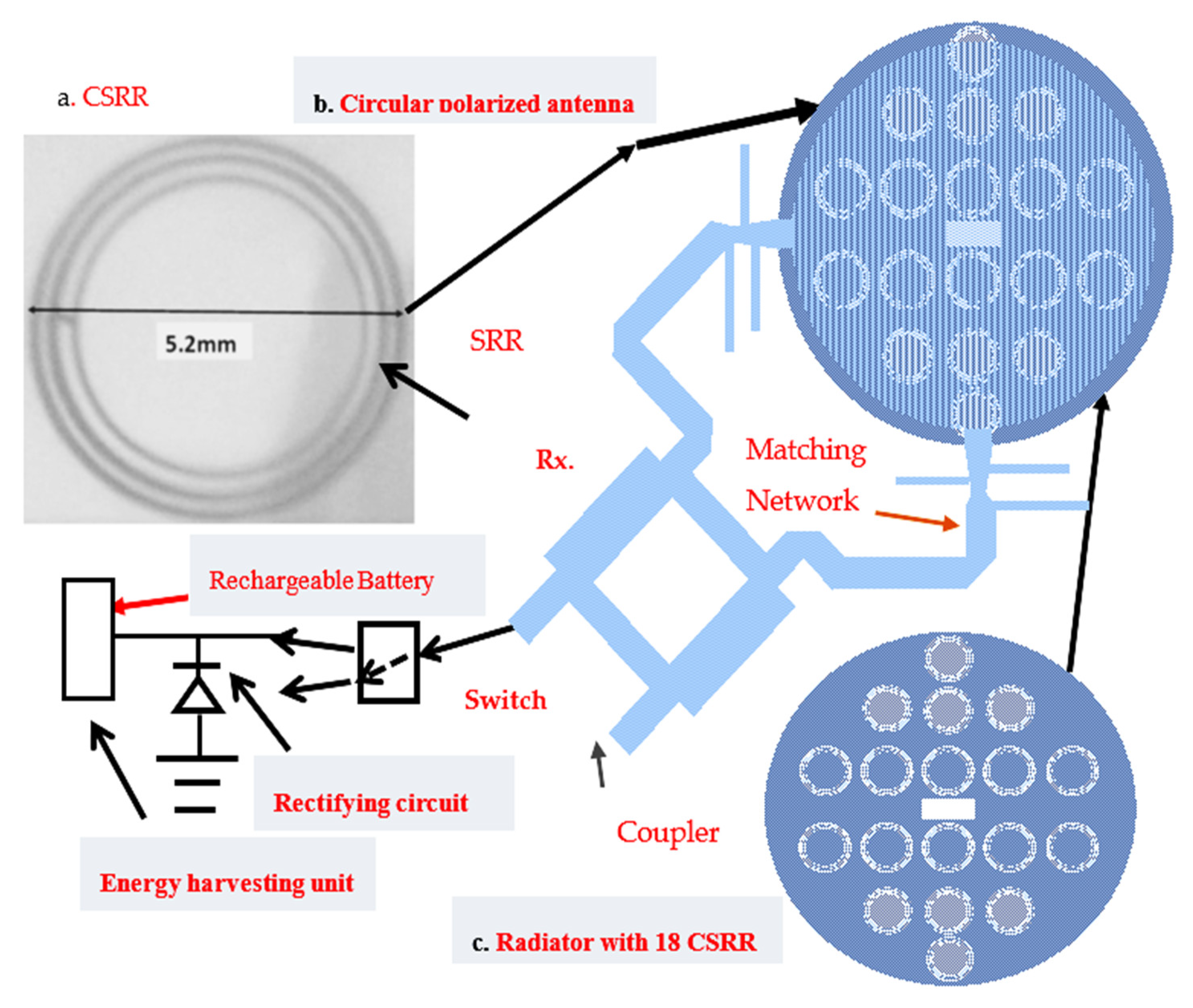
Article

Wearable Circular Polarized Antennas for Health Care, 5G, Energy Harvesting, and IoT Systems

Department of Electrical Engineering, ORT Braude College, Karmiel 2161002, Israel
Electronics 2022, 11(3), 427; https://doi.org/10.3390/electronics11030427
Submission received: 28 December 2021 / Revised: 26 January 2022 / Accepted: 27 January 2022 / Published: 30 January 2022
(This article belongs to the Special Issue Wearable Antennas for 5G, IoT, and Medical Applications)

Abstract

:
Novel circular polarized sensors and antennas for biomedical systems, energy harvesting, Internet of Things (IoT), and 5G devices are presented in this article. The major challenge in development of healthcare, IoT, 5G and communication systems is the evaluation of circular polarized active and passive wearable antennas. Moreover, a low-cost wearable sensor may be evaluated by printing the microstrip antenna with the sensor feed network and the active devices on the same substrate. Design considerations, comparison between simulation and measured results of compact circular polarized efficient sensors for wireless, 5G, energy harvesting, IoT, and medical systems are highlighted in this article. The electrical performance of the novel sensors and antennas on and near the user body were evaluated by employing electromagnetic software. Efficient passive and active metamaterial circular polarized antennas and sensors were developed to improve the system electrical performance. The wearable compact circular polarized passive and active sensors are efficient, flexible, and low-cost. The frequency range of the resonators, without Circular Split-Ring Resonators CSRRs, is higher by 4% to 10% than the resonators with CSRRs. The gain of the circular polarized antennas without CSRRs is lower by 2 dB to 3 dB than the resonators with CSRRs. The gain of the new passive antennas with CSRRs is around 7 dBi to 8.4 dBi. The bandwidth of the new circular polarized antennas with CSRRs is around 10% to 20%. The sensors VSWR is better than 3:1. The passive and active efficient metamaterials antennas improve the system performance.

1. Introduction

Basic theory and design of small printed antennas is discussed in [1]. The efficiency of small antennas is low, [2,3,4]. Compact printed metamaterials antennas and sensors are used in wireless communication systems and were discussed, evaluated and presented in several publications in this century, [2,3,4,5,6]. Printed dipoles, FIPA and loop antennas, printed Slots, microstrip antennas, and other compact antennas are employed in radars, Internet of Things (IoT), 5G, and healthcare systems [2,3,4,5,6]. Several types of small efficient wideband wearable antennas are presented in, [2,3,4]. Metamaterials are materials with periodic artificial structures. The metamaterial elements and structure define the electrical properties of the material. Metallic posts structures and periodic split ring resonators (SRRs) may be employed to produce structures with required permeability and dielectric constant as presented in [7,8,9,10,11]. Metamaterial technology may be employed to develop small efficient antennas for communication, wearable healthcare and IoT devices, [12,13,14,15,16]. In [6] the development of a metamaterial microstrip antenna was presented. In [6] the antenna gain, and bandwidth are similar, to those of patch antennas. In [8] structures with negative dielectric permittivity are analyzed. In [9], a model and setup to simulate and measure the polarity SRRs structures is presented. The model is used to compare measured results to computed results. In [12] a dual band transmission-line metamaterial antenna with two transmission line arms, is presented. The antenna bandwidth is 3% with 60% efficiency and 2.6 dBi directivity. The antenna gain is around 0.8 dBi. Compact radiators such as printed loops and dipoles, patches, and FIPA antennas suffer from low efficiency [2,3,4,5,16,17,18,19,20,21,22,23,24,25,26,27,28]. These antennas are linear polarized. Compact efficient metamaterial antennas may be important element in wearable medical and energy harvesting systems. In several 5G, energy harvesting, and medical systems, the polarization of the receiving signal may be horizontal, elliptical, or vertical. In these cases, the antenna should be circular polarized. Wearable communication and medical systems were presented in [2,3,4,5]. Small efficient wearable metamaterials antennas for medical systems are presented in [15,16]. Measurements of wearable antenna in vicinity of human body are presented in [17]. Active wearable antennas for wireless communication and medical systems are presented in [19].
A patient remote monitoring system in hospitals is presented in [29]. Wearable healthcare devices are used to increase disease cure and prevention. A wireless body area network with an adaptive thermal-aware protocol is discussed in [30]. In [31] a secure thermal-energy aware protocol is presented. In [32,33,34,35,36,37,38,39,40] wearable active antennas for medical applications are presented. Wearable medical sensors can monitor and check patient daily health [34,35]. Dual polarized dipole wearable antenna for medical applications are presented in [39]. Low-cost medical treatment may be achieved by online evaluation of a continuous measured medical information of a great number of patients.
  • The significance of wearables in today’s world[2,3,4,5]
  • Wearable antennas and sensors are used to monitor home medical devices to assist asthma, diabetes, and epilepsy patients.
  • Wearable antennas and medical sensors may are used to monitor hospital activities such as patient care, patient health monitoring, and personal monitoring.
  • Wearable antennas and sensors are used to operate IoT devices and systems.
  • Wearable Antennas and IoT Devices[2,3,4,5]
IoT systems are wireless communication devices of interrelated computing networks, personal devices, digital machines, mechanical machines, and medical sensors that have a unique identifiers (UIDs). IoT system consists of modules that use communication systems, sensors, processors, and antennas. IoT systems receive, transmit and process information received from their environments that are connected to the internet web. IoT devices are connected to an IoT gateway where the collected information is processed online or sent to data centers to be diagnosed and shared with other IoT devices. In several IoT and medical devices the polarization is not defined. In these cases, the antenna should be circular polarized.
  • Wearable antennas and IoT devices are used to automate processes, to reduce company hardware and to reduce labor costs.
  • IoT antennas and devices can transfer information between different devices and computers without human assistance.
  • IoT devices may have a complete control over routine services and tasks, helps people everyday life, and to work smarter.
  • IoT devices provides companies with an online observation how the company systems operate.
In this article, metamaterials technology is used to design high efficiency circular polarized antennas with harvesting energy unit for healthcare, 5G, IoT and communication sensors. Circular polarized metamaterial radiators were not presented in previous publications. Circular polarized and circular patch metamaterial antennas have significant advantages over regular printed antennas. Such as, the ease to develop circular polarized antennas, symmetry, and of exciting high order modes. The stacked circular polarized patch wearable antennas with CSRRs were developed for 5G, IoT and healthcare systems. The new sensors bandwidth, for VSWR, better than 3:1, is around 10% to 20%. The gain of the antennas with CSRRs is around 8dB. The sensors efficiency is higher than 90%. The energy harvesting units connected to the sensors provides self-powered efficient and compact sensors.
The progress in development of small antennas for communication, medical, and harvesting devices is presented in Table 1 and Table 2, based on information presented in [1,2,3,4,5]. Table 1 summarize the gain and the efficiency of printed compact antennas. Table 2 presents the bandwidth of printed compact antennas such as printed dipoles, patches, metamaterials, and fractal antennas.
The main goal of the paper is to present wearable circular polarized efficient receiving and transmitting sensors for medical, IoT, and communication systems. The paper present examples of wearable efficient receiving and transmitting sensors and antennas at the frequency range of wireless, WLAN, and 5G frequencies from 1 GHz up to 3 GHz.
First example is a Circular polarized passive metamaterial sensor and harvester, Section 2. Second example is an Active Receiving Compact Circular Polarized Antenna with Energy Harvesting Module, Section 3. An Active Circular Polarized Metamaterial Transmitting Sensor is presented in Section 4. Several sensors should be able to transmit and receive data. The fourth example is a Circular Polarized Transceiver with an Energy Harvesting Unit. The energy harvesting design is presented in Section 9.

2. Circular Polarized Metamaterial Stacked Antenna with Energy Harvesting Module

A circular patch antenna with CSRR may be used as a sensor for IoT and medical applications. The CSRRs improve the antenna effective area and gain. The sensor presented in Figure 1 consists of a circular stacked patch, a branch line coupler, and a harvesting unit. The circular stacked patch consists of a resonator and a matching feed network that is printed on the first layer. The circular radiator with the CSSR is printed on the second layer. The resonator excites the radiator by means of electromagnetic coupling. The branch line coupler feed the circular patch to generate a circular polarized antenna. The RF dual mode energy harvesting unit may recharge the battery when the switch is connected to the harvesting unit. Electromagnetic power is converted to DC power by a rectifying diode. The rectifier can be a half-wave or a full-wave rectifier. The RF harvesting unit consists of an antenna, a rectifying diode, and a rechargeable battery, see Figure 1. The circular radiator with 18 CSRRs, as presented in Figure 1, are etched on a 1.6 mm thick substrate with dielectric constant of 2.25. The substrate tangent loss is 0.003. The antenna diameter is 35.5 mm. The antenna resonates in the frequency range from 2.4 GHz to 2.9 GHz. TM11 mode resonant frequency may be computed by Equation (1), [1]. The radius a e of the circular patch may be computed by using equation (2), c is the light velocity in vacuum. The effective dielectric constant is ε e . The computed diameter of the antenna at 2.7 GHz is 46 mm. The CSRRs design considerations was discussed in [2,3,4,5,15,16]. The radius of the patch without CSRR is higher by 24% than the radius of the patch with CSRR. The CSRR strip width is 0.2 mm and the outer ring diameter is 5.2 mm, as presented in Figure 1a. Patches and CSRR dimensions were optimized by using electromagnetic software, [41].
f = 1.8412 c 2 π a e ε e
a e = 1.8412 c 2 π f ε e
As shown in Figure 2 the bandwidth of the stacked circular polarized antenna is around 20%, computed and measured, for VSWR better than 2:1. The antenna gain is around 7.9 dBi with 82° beam width, as shown in Figure 3a. Comparison of computed and measured gain is presented in Figure 3b.
The gain of similar antennas without CSRR is lower by 2 dB to 3 dB than the gain of the antenna with CSSR shown in Figure 1. The antenna efficiency is around 87%.
Branch Line Coupler Design—A microstrip branch line coupler consists of four quarter wavelength microstrip lines a presented in Figure 4. The input signal in port 1 is divided equally, −3 dB, to port 2 and 3. The phase difference between port 2 and 3 is 90°. Port 4 is isolated. Dimensions of the coupler are listed in Table 3. The coupler measured bandwidth is around 50%, S11 results are shown in Figure 5. The measured S13 transfer parameter is shown in Figure 6. The branch line coupler phase difference between ports 2 and 3 is 90°, as presented in Figure 7. The simulated and measured isolation between ports 2 and 3 is −10 dB at 2.2 GHz and −30 dB at 2.8 GHz.

3. Active Receiving Compact Circular Polarized Antenna with Energy Harvesting Module

Block diagram of a receiver with an active circular polarized metamaterial antenna with energy harvesting module is shown in Figure 8. The circular active patch antenna with CSRR may be used as a sensor for IoT and medical applications. A Low noise amplifier, LNA, is assembled on the matching circuit board of the circular polarized metamaterial sensor. The Mini-Circuits LNA TAV541, is assembled on the antenna substrate as shown in Figure 8 and Figure 9. The circular polarized antenna is etched on a 1.6mm thick substrate with a dielectric constant of 2.25. An integral input matching circuit match the circular patch to the LNA, as presented in Figure 9. An integral output matching circuit matches the LNA output port to the system. The dimensions of the matching networks are less than 22 × 28 mm and are part of the antenna feed network. The bias voltages to the active sensor are supplied by an integral DC circuit. The LNA electrical and mechanical features are given in Table 4. In Table 5 the LNA noise specifications are listed. The LNA S parameters are given in TAV541 data sheets. The measured reflection coefficient of the circular polarized antenna on a human body is shown in Figure 10. The VSWR of the antenna in frequency range from 1.8 GHz to 3 GHz is improved from 4:1 to 2:1, by using a matching network. The measured bandwidth of the active sensor is around 65% for VSWR better than 3:1. The antenna feed circuit was tuned and optimized, as presented in Figure 11. The improved matching circuit improves the active sensor gain by 2 dB to 3 dB. The measured gain on human body of the active sensor is 13 + 1 dB. The sensor gain is 14.1 dB at 2.6 GHz and decreases to 11 dB at 3.1 GHz, see Figure 12. The measured sensor noise figure is lower than 1.2 dB in the frequency range from 1.8 GHz to 3.1 GHz. Measurement setups of wearable sensors are discussed in [2,3,4,5]. Table 6 presents a good agreement between simulated and measured sensor electrical parameters.

4. Active Circular Polarized Metamaterial Transmitting Sensor

A block diagram of a circular polarized transmitting link is presented in Figure 13. A circular polarized transmitting sensor is shown in Figure 14. The antenna radius is 19.7 mm.
The High Power Amplifier HPA, GaAs MESFET VNA25, and the antenna are assembled on the same substrate. The HPA is connected to the branch coupler of the circular polarized sensor. The antenna is matched to the power amplifier by a printed matching circuit. The transmitter is matched to the amplifier by the input matching circuit. The matching circuits, dimensions are less than 23 × 29 mm. The HPA features are listed in Table 7. The HPA S4P parameters are presented in Table 8. The antenna optimized matching network is shown in Figure 15a. The antenna bandwidth was improved to 55% for S11 lower than −6 dB. The S11 of the transmitting circular polarized antenna is lower than −9 dB in the frequency range from 1.9 to 3.1 GHz as shown in Figure 15b.
Plots of S11 parameters on a smith chart diagram, without and with the output matching circuit, are presented in Figure 15b. Figure 16 presents the gain of the optimized active transmitting antenna on human body. The antenna measured gain is 12.0 ± 2 dB, in the frequency range of 1.8 to 3.2 GHz.
The 1 dBc output power of the transmitting sensor is around 17 dBm to 19 dBm.

5. Wideband Metamaterial Wearable Circular Polarized Antenna and Energy Harvester Sensor

A wideband metamaterial wearable circular polarized energy harvester sensor is shown in Figure 17a. The sensor feed circuit and the radiating patch are etched on a 1.6 mm thick substrate, with 2.25 dielectric constant. The radius of the circular patch is 17.7 mm.
The circular radiating patch with 18 CSRRs are etched on a 1.6 mm thick substrate, with 2.25 dielectric constant. The maximum number of CSRRs that can be printed on the circular patch is 18. The circular radiator diameter is 39.5 mm. The antenna bandwidth can be optimized up to 20%, by varying the spacing between the radiator and the resonator from 0 mm up to 10 mm.
The radius of the antenna without CSRR is bigger by 22% than the radius of the antenna with CSRR. The dimensions of the CSRR are shown in Figure 17b. The CSSR radius is 2.6 mm and the strips width is 0.2 mm. The antenna reflection coefficients, S11 and S22, are presented in Figure 18. The antenna frequency range is 2.6 GHz + 8%, for S11 lower than −6 dB. The circular patch efficiency is around 90%. The directivity and gain of the antenna is around 8.4 dBi, and the antenna beam width is 82°, see Figure 19a. The computed and measured gain is presented in Figure 19b. The directivity of the antenna without CSRR is lower by 2 to 3 dB than the directivity of the antenna with CSRR. The circular polarization radiation pattern of the antenna is presented in Figure 19c. The measured axial ratio of the circular polarized antenna is around +0.5 dB. The antenna was developed and optimized by using RF simulation software.

6. Circular Polarized Sensing Transceiver with an Energy Harvesting Unit

A compact circular polarized transceiver with a wideband metamaterial circular patch antenna with an energy harvesting unit is presented in Figure 20. The LNA, LNA specifications was given in Section 3, is assembled on the PCB of the receiving sensor, see Figure 20. The HPA is an integral part of the transmitting module. A surface mount SPDT is used to select between the receiving and transmitting mode. The antenna feed network and the radiating patch are etched on a board with 2.25 dielectric constant and 1.6 mm thick. The transceiver may be used to transmit and receive data in IoT and medical applications. The diameter of the antenna is 36 mm. The circular radiating patch with 18 CSRRs are etched on a 1.6 mm thick substrate, with 2.25 dielectric constant. The circular radiator diameter is 39.5 mm. The LNA and the HPA are matched to the antenna and to the transceiver by matching networks. The required bias voltages are supplied to the amplifiers by an integral DC network. The circular polarized antenna measured S11 parameter of the transmitting module is presented in Figure 21. The measured active receiving and transmitting antennas frequency range is 2.6 + 30%, for S11 lower than −6 dB. The antenna gain, S21, of the receiving and transmitting channels on human body, are shown in Figure 22 and Figure 23. The transmitting channel gain is 11 ± 3 dB for frequencies from 1.8 GHz to 3.2 GHz. In this frequency range the receiver gain is 12 ± 2 dB and the receiving channel noise Figure is 1 ± 0.4 dB. The transceiver matching networks were optimized to improve the transmitting and receiving channels bandwidth up to 50% for S11 lower than −6 dB. The S11 parameters of the transmitting and receiving channels without the matching networks is around −4 dB for frequencies from1.8 to 3.1 GHz. The good agreement between simulated and measured results is shown in Table 11.
An energy harvesting unit is connected to the circular polarized sensor as shown in Figure 20. The energy harvesting module is a dual mode harvester that may recharge the battery when the switch is connected to the rectifier. RF power is converted to DC power by using a diode rectifying circuit that can operate as a half-wave or a full-wave rectifier. Harvester modules consist of an AC power collector such as antennas, a rectifying diode, and a rechargeable battery, see Figure 1. An energy harvesting unit may be connected to the transmitter via a switch, or via a −20 dB coupler, and charge the battery when the transmitter is in standby mode.

7. Wearable Circular Polarized Metamaterial Sensors for Healthcare and IoT Systems

The circular polarized sensors and antennas discussed in this article may be employed in healthcare sensors, and IoT devices.
The sensors electrical performance variation near the human body were simulated by generating a model of the human body and the antenna as shown in Figure 24a.
In Table 9 electrical characteristics of human body tissues are listed, [16]. The influence of human body on the antenna performance is simulated by evaluating the antenna reflection coefficient on human body. At fat tissues the dielectric constant is 5, and 45 at the stomach zone, and increase to 128 at the Small intestine area. The variation of the electrical characteristics of the body tissues affects the electrical performance of the antenna. The sensor resonant frequency is shifted up to 8%, in different locations of the sensor on the patient body. The circular polarized sensors may be located inside a belt, see Figure 24b. The belt electrical characteristics and thickness change the sensor electrical performance. The sensors electrical and mechanical parameters were tuned to achieve the best sensor electrical and mechanical parameters. The sensors electrical performance was simulated and measured for air spacing between the sensors and human body up to 20mm at different areas on the patient body. Table 10 compare results between simulated and measured results of sensors without and with CSRR. Table 11 compare results between simulated and measured results of wearable antennas.
As presented in Table 10 and Table 11 there is a good agreement between simulated and measured results. Results listed in these tables verifies that the gain of the antennas without CSRR is lower by around 2.5 dB than the antennas with CSRR. Electrical performance of patches, loop, slot antennas, dipoles, and other antennas were given in [2,3,4,5].

8. Circular Polarized Stacked Antenna with CSSRs on the Resonator with RF Harvester

The circular polarized patch antenna with 18 CSRRs on the resonator is shown in Figure 25. The resonator is etched on a substrate with dielectric constant of 4.5 and 1.6 mm thick. The radiator is etched on a substrate with dielectric constant of 2.2 and 1.6 mm thick. The resonator diameter is 39 mm. The radiator diameter is 40 mm. The antenna resonates at frequencies from 2.4 GHz to 2.9 GHz. The simulated and measured frequency range of the circular polarized antenna is 2.6 + 0.3 GHz for VSWR better than 3:1, as presented in Figure 26. The antenna beam width is around 82°. The circular polarized radiator gain is around 8.3 dBi, with efficiency of 95%. Photos of prototypes of the Active Stacked Circular patch and the Circular Polarized patch are shown in Figure 27a,b. The phase difference between ports A and B in Figure 27b is 90°. In Figure 27c components, modules, and block diagram of the sensor are shown. Healthcare monitoring system with the proposed wearable compact sensors is presented in Figure 28. Wearable medical sensors, IoT devices, and sport monitoring devices may measure a person blood pressure, sweat rate, temperature, Heartbeat, perform gait analysis and other health parameters of the patient as shown in Figure 28. In clinical practice and in biomechanical research gait analysis provides very useful information about the patient. Wearable gait sensors analysis provides online low cost massive and repeatable data over long time periods about the patient motion performance. Wearable sensors at frequencies from 2.4 GHz to 3 GHz are used in healthcare, sport, emergency devices, and in several other applications.

9. Energy Harvesting Module for Healthcare Sensors, IoT, 5G, and Communication Systems

As shown in Figure 1 the energy harvesting module consists of compact circular polarized patch, AC to DC converter, and a rechargeable battery. The energy harvesting modules and the antenna provide a self-powered sensor. The rectifier diode converts RF energy, AC energy, to DC energy. Two types of diode rectifiers are usually employed a half wave rectifier or a full wave rectifier, [42,43,44,45]. Figure 29 presents a half wave rectifier that converts only the positive voltage of the received signal. The rectifier harvest maximum 50% of the RF signal with the efficiency of 40.6%. Around 0.4 of the input electromagnetic energy is converted into DC power and may charge the batteries. Figure 30 presents a full wave rectifier. This diode rectifier converts RF energy to DC power. As presented in Figure 30 the bridge rectifier consists of four diodes. During the positive half cycle voltage, point A will be positive and point B will be negative. Diodes D1 and D2 will become forward biased and D3 and D4 will be reversed biased. The rectifier output DC voltage, V O D C = 2 V m / π .
A capacitor connected in shunt to the rectifier resistor improves the rectifier output voltage as presented in Figure 30. The efficiency of the full wave rectifier is 81.2%.
Green renewable energy is provided by energy harvesters and may eliminate the usage of power cords and the need to replace batteries frequently. Wearable RF System with energy harvesting unit for IoT, healthcare and 5G, applications are presented in Figure 31. The harvesting module and the compact rechargeable battery is placed on the user t-shirt as shown in Figure 31.
In 2021 every person uses wireless communication devices, smart phones, tablet and other RF devices. This result in a significant increase in the amount of electromagnetic energy in free space. The expected amount of RF wave in free space in 2020 was around 50 Exa-bytes, EB, per month. However, the expected amount of radio wave in free space in 2026 is expected to be around 185 Exa-bytes per month. In RF power harvesters, the RF waves propagating in the air can be collected by the circular polarized antennas and converted to DC power that is used to charge electric devices, wearable sensors, batteries and other wearable modules. Harvested power amount in malls and stadiums range from 1 µW/cm2 to 5 mW/cm2.
The harvesting system efficiency increases as function of the electromagnetic power collected by the harvesting system as listed in Table 12. The amplifier amplifies the input power collected by the energy harvesting system and improves the efficiency of the harvesting system. Results listed in Table 12 are also presented by companies that manufacture commercial RF energy harvesting systems. If the RF radiating sources are close to the harvesting system, the RF power collected by the harvester will be higher.

10. Conclusions

The active and passive circular polarized antennas and sensors discussed in this article are compact, wideband, efficient, and low-cost. Energy harvesting unit is connected to the circular polarized sensors. RF waves propagating in the air may be collected by the harvesters and converted to DC power that may recharge the medical system batteries, wearable sensors, and other wearable modules. Development of circular polarized efficient active and passive wearable sensors and radiators are very important goal in the design of medical sensors, 5G, IoT, and healthcare devices. In the receiving sensors, the LNA is an integral module of the receiving sensor. In transmitting sensors the HPA, is an integral module of the transmitter. The output power of the circular polarized sensor is around 19dBm. Passive and active circular polarized compact sensors performance such as efficiency, bandwidth, noise figure, gain, and radiation pattern were presented in this paper. The circular polarized metamaterial patches and sensors presented in this research can be used in wideband wearable RF devices for IoT, 5G, sport, and healthcare devices. Metamaterials are employed to design efficient radiating elements and sensors. The resonant frequency of the circular polarized radiator with CSRR is lower by 5% to 10% than the radiators without CSRR. Directivity and gain of the circular polarized patches with CSRR is better by 2 dB to 3 dB than the radiators without CSRR. Electrical simulated and measured results of several efficient sensors with and without CSRRs are discussed and summarized in this article. Bandwidth of the active circular polarized antennas is around 25% to 40% for reflection coefficient lower than −8 dB. The circular polarized antenna efficiency, bandwidth, gain and radiation pattern were improved by optimizing the sensor dimensions. The active receiving and transmitting circular polarized antennas gain is around 14 dB. The circular polarized antennas circularity is around ±0.5 dB circularity. The receiving module noise figure is around 1 dB. The wearable circular polarized sensors can operate as linear and dual polarized sensors. The harvesting unit input power in shopping centers, stadiums, and in healthcare centers can be between −10 dBm to 10 dBm.
The circular polarized sensors and devices discussed in this paper may operate in healthcare systems that improves the daily health and the life conditions of patients. Wearable sensors and medical devices seem to be an important choice for medical organizations, medical centers, and patients. Circular polarized wearable sensors support the evaluation of healthcare devices with online immediate physician response to cure and improve patients’ health. The energy harvesting units connected to the sensors provides self-powered autonomous compact sensors.
In future work more types of fractal and metamaterial efficient compact antennas and sensors for healthcare, 5G, IoT communication devices with energy harvesting units will be developed. In future research metamaterial fractal linear and dual polarized efficient sensors and antennas for wireless communication systems, healthcare, and other applications will be developed.

Funding

This research received no external funding.

Institutional Review Board Statement

Not applicable.

Informed Consent Statement

Not applicable.

Data Availability Statement

Not applicable.

Conflicts of Interest

The authors declare no conflict of interest.

References

  1. James, J.R.; Hall, P.S.; Wood, C. Microstrip Antenna Theory and Design; Institution of Engineering and Technology (IET): London, UK, 1981. [Google Scholar]
  2. Sabban, A. Novel Wearable Antennas for Communication and Medical Systems; Taylor & Francis Group: Boca Raton, FL, USA, 2017. [Google Scholar]
  3. Sabban, A. Wideband RF Technologies and Antennas in Microwave Frequencies; Wiley: Hoboken, NJ, USA, 2016. [Google Scholar]
  4. Sabban, A. Low Visibility Antennas for Communication Systems; Taylor & Francis: Boca Raton, FL, USA, 2015. [Google Scholar]
  5. Sabban, A. New Wideband Printed Antennas for Medical Applications. IEEE Trans. Antennas Propag. 2013, 61, 84–91. [Google Scholar] [CrossRef]
  6. Rajab, K.; Mittra, R.; Lanagan, M. Size Reduction of Microstrip Antennas using Metamaterials. In Proceedings of the 2005 IEEE APS Symposium, Washington, DC, USA, 3–8 July 2005. [Google Scholar]
  7. Pendry, J.B.; Holden, A.J.; Stewart, W.J.; Youngs, I. Extremely Low Frequency Plasmons in Metallic Meso-structures. Phys. Rev. Lett. 1996, 76, 4773–4776. [Google Scholar] [CrossRef] [PubMed] [Green Version]
  8. Pendry, J.B.; Holden, A.; Robbins, D.; Stewart, W. Magnetism from conductors and enhanced nonlinear phenomena. IEEE Trans. Microw. Theory Tech. 1999, 47, 2075–2084. [Google Scholar] [CrossRef] [Green Version]
  9. Marque’s, R.; Mesa, F.; Martel, J.; Medina, F. Comparative analysis of edge and broadside coupled split ring resonators for metamaterial design—Theory and Experiment. IEEE Trans. Antennas Propag. 2003, 51, 2572–2581. [Google Scholar] [CrossRef] [Green Version]
  10. Marque´s, R.; Baena, J.D.; Martel, J.; Medina, F.; Falcone, F.; Sorolla, M.; Martin, F. Novel small resonant electromagnetic particles for metamaterial and filter design. In Proceedings of the ICEAA’03, Torino, Italy, 8–12 September 2003; pp. 439–442. [Google Scholar]
  11. Marqués, R.; Martel, J.; Mesa, F.; Medina, F. Left-Handed-Media Simulation and Transmission of EM Waves in Subwavelength Split-Ring-Resonator-Loaded Metallic Waveguides. Phys. Rev. Lett. 2002, 89, 183901. [Google Scholar] [CrossRef]
  12. Zhu, J.; Eleftheriades, G. A Compact Transmission-Line Metamaterial Antenna with Extended Bandwidth. IEEE Antennas Wirel. Propag. Lett. 2008, 8, 295–298. [Google Scholar] [CrossRef]
  13. Baena, J.D.; Marque’s, R.; Martel, J.; Medina, F. Experimental results on metamaterial simulation using SRR-loaded Waveguides. In Proceedings of the IEEE-AP/S International Symposium on Antennas and Propagation, Columbus, OH, USA, 22–27 June 2003; pp. 106–109. [Google Scholar]
  14. Marques, R.; Martel, J.; Mesa, F.; Medina, F. A new 2D isotropic left-handed metamaterial design: Theory and experiment. Microw. Opt. Technol. Lett. 2002, 35, 405–408. [Google Scholar] [CrossRef]
  15. Sabban, A. New Compact Wearable Metamaterials Circular Patch Antennas for IoT, Medical and 5G Applications. Appl. Syst. Innov. 2020, 3, 42. [Google Scholar] [CrossRef]
  16. Sabban, A. Small Wearable Metamaterials Antennas for Medical Systems. Appl. Comput. Electromagn. Soc. J. 2016, 31, 434–443. [Google Scholar]
  17. Sabban, A. Microstrip Antenna Arrays. In Microstrip Antennas; Nasimuddin, N., Ed.; InTech: London, UK, 2011; pp. 361–384. ISBN 978-953-307-247-0. Available online: http://www.intechopen.com/articles/show/title/microstrip-antenna-arrays (accessed on 28 November 2011).
  18. Sabban, A. Wearable Antenna Measurements in Vicinity of Human Body. Wirel. Eng. Technol. 2016, 7, 97–104. [Google Scholar] [CrossRef] [Green Version]
  19. Sabban, A. Active Compact Wearable Body Area Networks for Wireless Communication, Medical and IOT Applications. Appl. Syst. Innov. J. 2018, 1, 46. [Google Scholar] [CrossRef] [Green Version]
  20. Chirwa, L.; Hammond, P.; Roy, S.; Cumming, D.R.S. Electromagnetic radiation from ingested sources in the human intestine between 150 MHz and 1.2 GHz. IEEE Trans. Biomed. Eng. 2003, 50, 484–492. [Google Scholar] [CrossRef] [PubMed]
  21. Werber, D.; Schwentner, A.; Biebl, E.M. Investigation of RF transmission properties of human tissues. Adv. Radio Sci. 2006, 4, 357–360. [Google Scholar] [CrossRef]
  22. Gupta, B.; Sankaralingam, S.; Dhar, S. Development of wearable and implantable antennas in the last decade: A review. In Proceedings of the 2010 10th Mediterranean Microwave Symposium, Guzelyurt, Cyprus, 25–27 August 2010; pp. 251–267. [Google Scholar]
  23. Thalmann, T.; Popovic, Z.; Notaros, B.M.; Mosig, J.R. Investigation and design of a multi-band wearable antenna. In Proceedings of the 3rd European Conference on Antennas and Propagation, EuCAP 2009, Berlin, Germany, 23–27 March 2009; pp. 462–465. [Google Scholar]
  24. Salonen, P.; Rahmat-Samii, Y.; Kivikoski, M. Wearable antennas in the vicinity of human body. In Proceedings of the IEEE Antennas and Propagation Society Symposium, Monterey, CA, USA, 20–25 June 2004; pp. 467–470. [Google Scholar]
  25. Kellomäki, T.; Heikkinen, J.; Kivikoski, M. Wearable antennas for FM reception. In Proceedings of the 2006 First European Conference on Antennas and Propagation, Nice, France, 6–10 November 2006; pp. 1–6. [Google Scholar]
  26. Lee, Y. Antenna Circuit Design for RFID Applications; Application Note 710c; Microchip Technology Inc.: Chandler, AZ, USA, 2003. [Google Scholar]
  27. Sabban, A. Microstrip Antenna and Antenna Arrays. U.S. Patent 4,623,893, 18 November 1986. [Google Scholar]
  28. Wheeler, H.A. Small antennas. IEEE Trans. Antennas Propag. 1975, 23, 462–469. [Google Scholar] [CrossRef]
  29. Jamil, F.; Ahmad, S.; Iqbal, N.; Kim, D. Towards a Remote Monitoring of Patient Vital Signs Based on IoT-Based Blockchain Integrity Management Platforms in Smart Hospitals. Sensors 2020, 20, 2195. [Google Scholar] [CrossRef] [Green Version]
  30. Jamil, F.; Iqbal, M.A.; Amin, R.; Kim, D. Adaptive Thermal-Aware Routing Protocol for Wireless Body Area Network. Electronics 2019, 8, 47. [Google Scholar] [CrossRef] [Green Version]
  31. Shahbazi, Z.; Byun, Y.-C. Towards a Secure Thermal-Energy Aware Routing Protocol in Wireless Body Area Network Based on Blockchain Technology. Sensors 2020, 20, 3604. [Google Scholar] [CrossRef]
  32. Lin, J.; Itoh, T. Active integrated antennas. IEEE Trans. Microw. Theory Tech. 1994, 42, 2186–2194. [Google Scholar] [CrossRef]
  33. Mortazwi, A.; Itoh, T.; Harvey, J. Active Antennas and Quasi-Optical Arrays; John Wiley & Sons: New York, NY, USA, 1998. [Google Scholar]
  34. Jacobsen, S.; Klemetsen, Ø. Improved Detectability in Medical Microwave Radio-Thermometers as Obtained by Active Antennas. IEEE Trans. Biomed. Eng. 2008, 55, 2778–2785. [Google Scholar] [CrossRef]
  35. Jacobsen, S.; Klemetsen, O. Active antennas in medical microwave radiometry. Electron. Lett. 2007, 43, 606. [Google Scholar] [CrossRef]
  36. Ellingson, S.W.; Simonetti, J.H.; Patterson, C.D. Design and evaluation of an active antenna for a 29–47 MHz radio telescope array. IEEE Trans. Antennas Propag. 2007, 55, 826–831. [Google Scholar] [CrossRef]
  37. Segovia-Vargas, D.; Castro-Galan, D.; Munoz, L.E.G.; González-Posadas, V. Broadband Active Receiving Patch with Resistive Equalization. IEEE Trans. Microw. Theory Tech. 2008, 56, 56–64. [Google Scholar] [CrossRef]
  38. Rizzoli, V.; Costanzo, A.; Spadoni, P. Computer-Aided Design of Ultra-Wideband Active Antennas by Means of a New Figure of Merit. IEEE Microw. Wirel. Compon. Lett. 2008, 18, 290–292. [Google Scholar] [CrossRef]
  39. Sabban, A. A New Wideband Stacked Microstrip Antenna. In Proceedings of the IEEE Antenna and Propagation Symposium, Houston, TX, USA, 23–26 May 1983. [Google Scholar]
  40. Sabban, A. Dual Polarized Dipole Wearable Antenna. U.S. Patent 8,203,497, 19 June 2012. [Google Scholar]
  41. ADS Momentum Software, Keysightt. Available online: http://www.keysight.com/en/pc-1297113/advanced-design-system-ads?cc=IL&lc=eng (accessed on 3 January 2018).
  42. Paradiso, J.A.; Starner, T. Energy scavenging for mobile and wireless electronics. IEEE Pervasive Comput. 2005, 4, 18–27. [Google Scholar] [CrossRef]
  43. Valenta, C.R.; Durgin, G.D. Harvesting wireless power: Survey of energy-harvester conversion efficiency in far-field, wireless power transfer systems. IEEE Microw. Mag. 2014, 15, 108–120. [Google Scholar]
  44. Nintanavongsa, P.; Muncuk, U.; Lewis, D.R.; Chowdhury, K.R. Design optimization and implementation for RF energy harvesting circuits. IEEE J. Emerg. Sel. Top. Circuits Syst. 2012, 2, 24–33. [Google Scholar] [CrossRef]
  45. Devi, K.K.A.; Sadasivam, S.; Din, N.M.; Chakrabarthy, C.K. Design of a 377 Ω patch antenna for ambient RF energy harvesting at downlink frequency of GSM 900. In Proceedings of the 17th Asia Pacific Conference on Communications (APCC ’11), Sabah, Malaysia, 2–5 October 2011; pp. 492–495. [Google Scholar]
Figure 1. (a) Single CSRR (b) Circular polarized sensor and harvester. (c) The radiator.
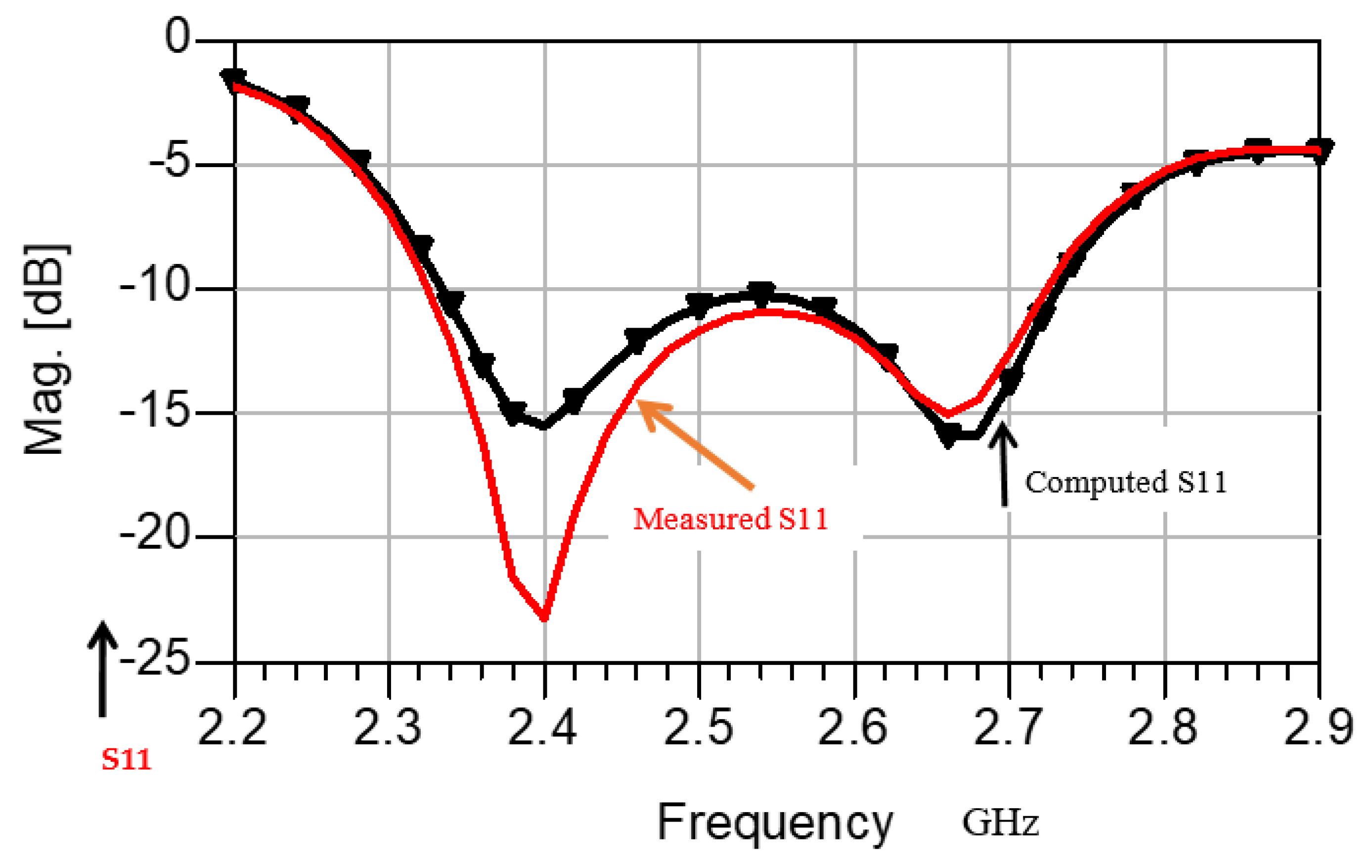
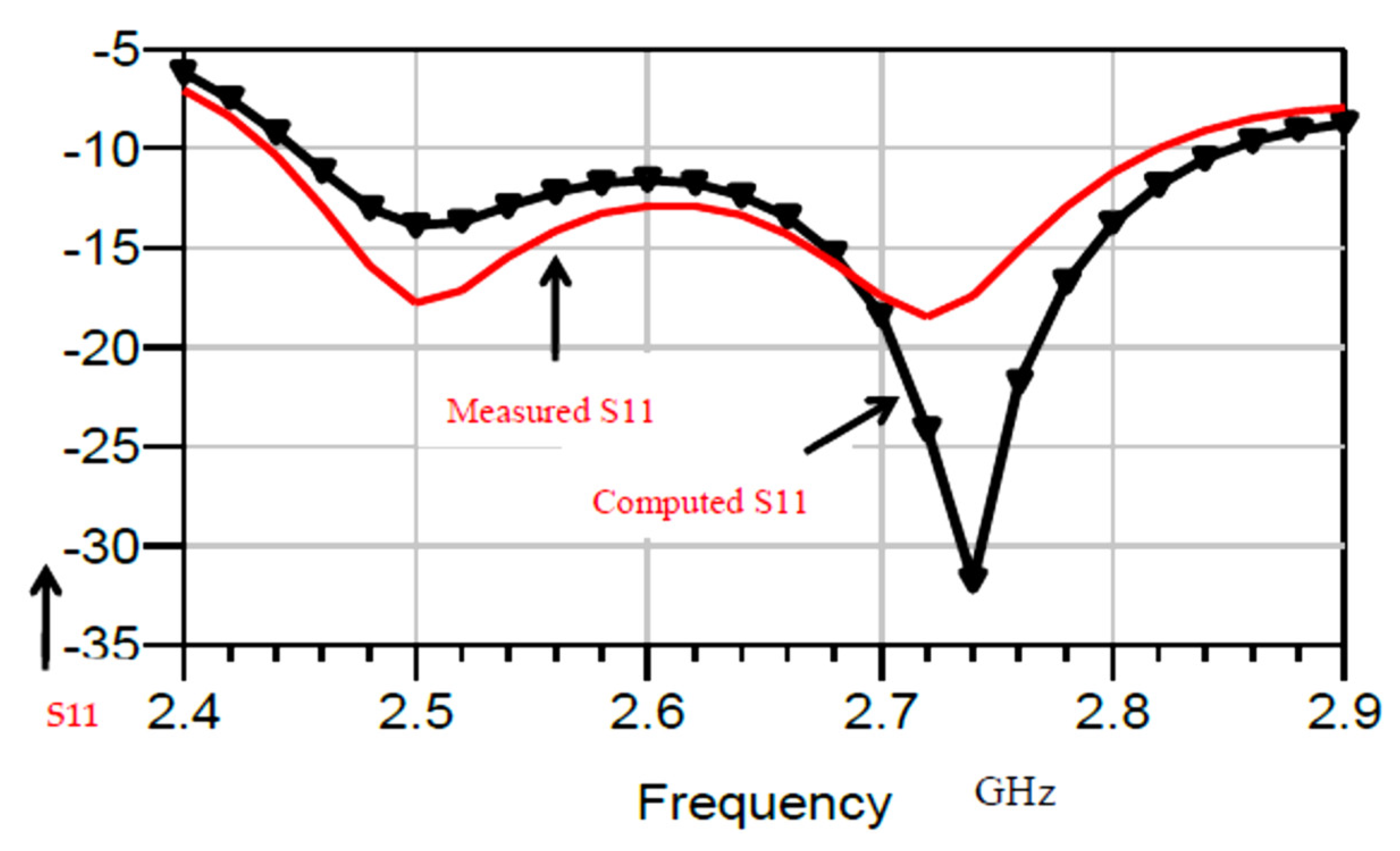
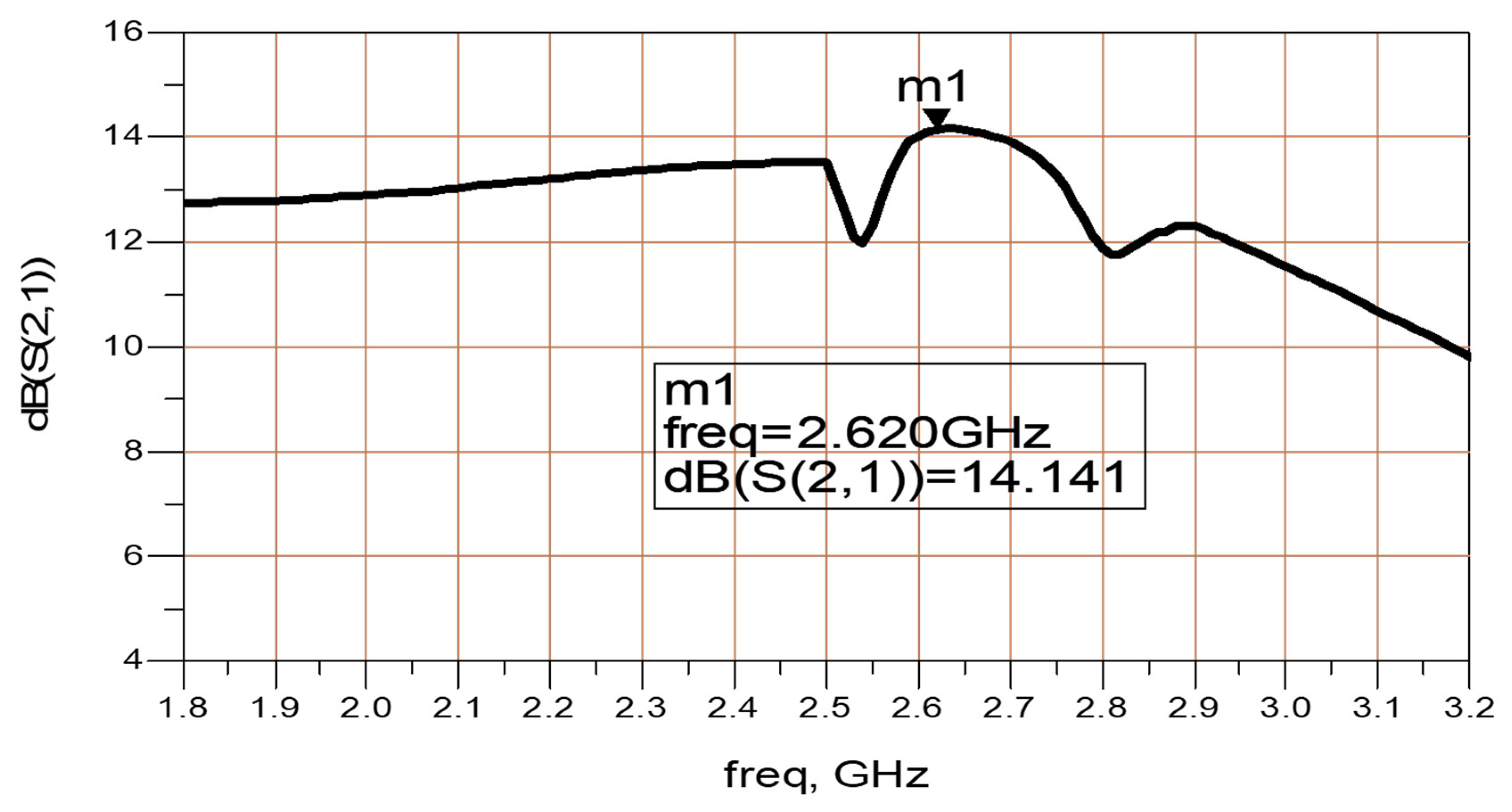
Electronics 11 00427 g001
Figure 2. Computed and measured S11 of the metamaterial circular polarized antenna.
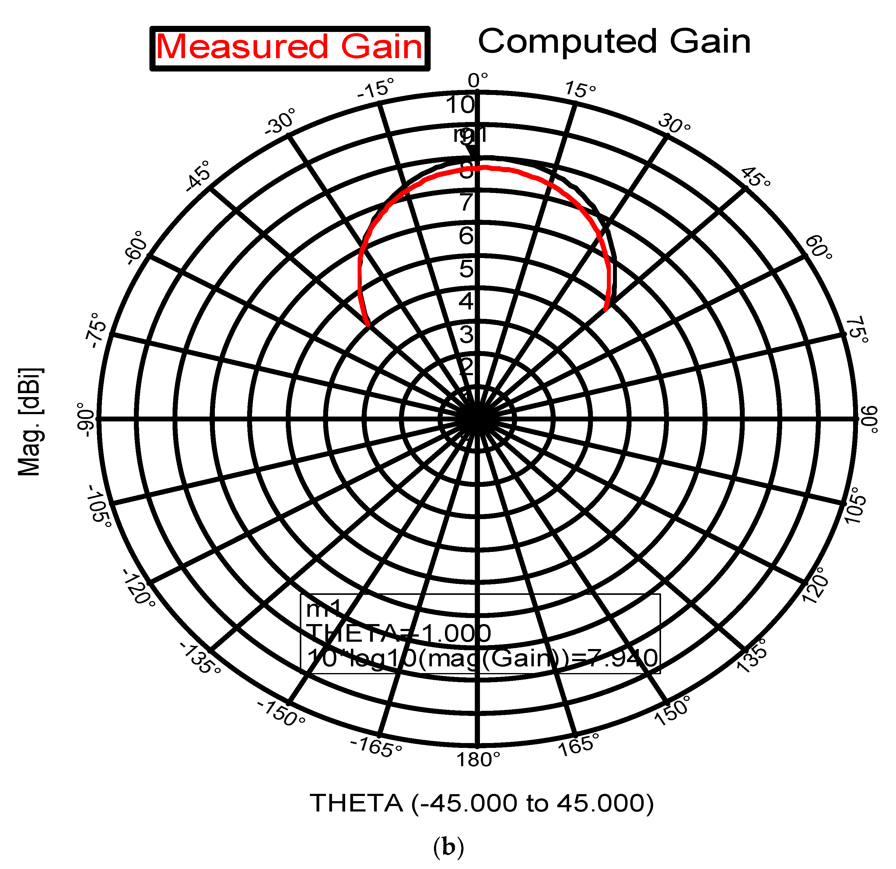
Electronics 11 00427 g002
Figure 3. (a) Radiation pattern of the circular polarized, at 2.6 GHz. (b) Comparison of computed and measured.
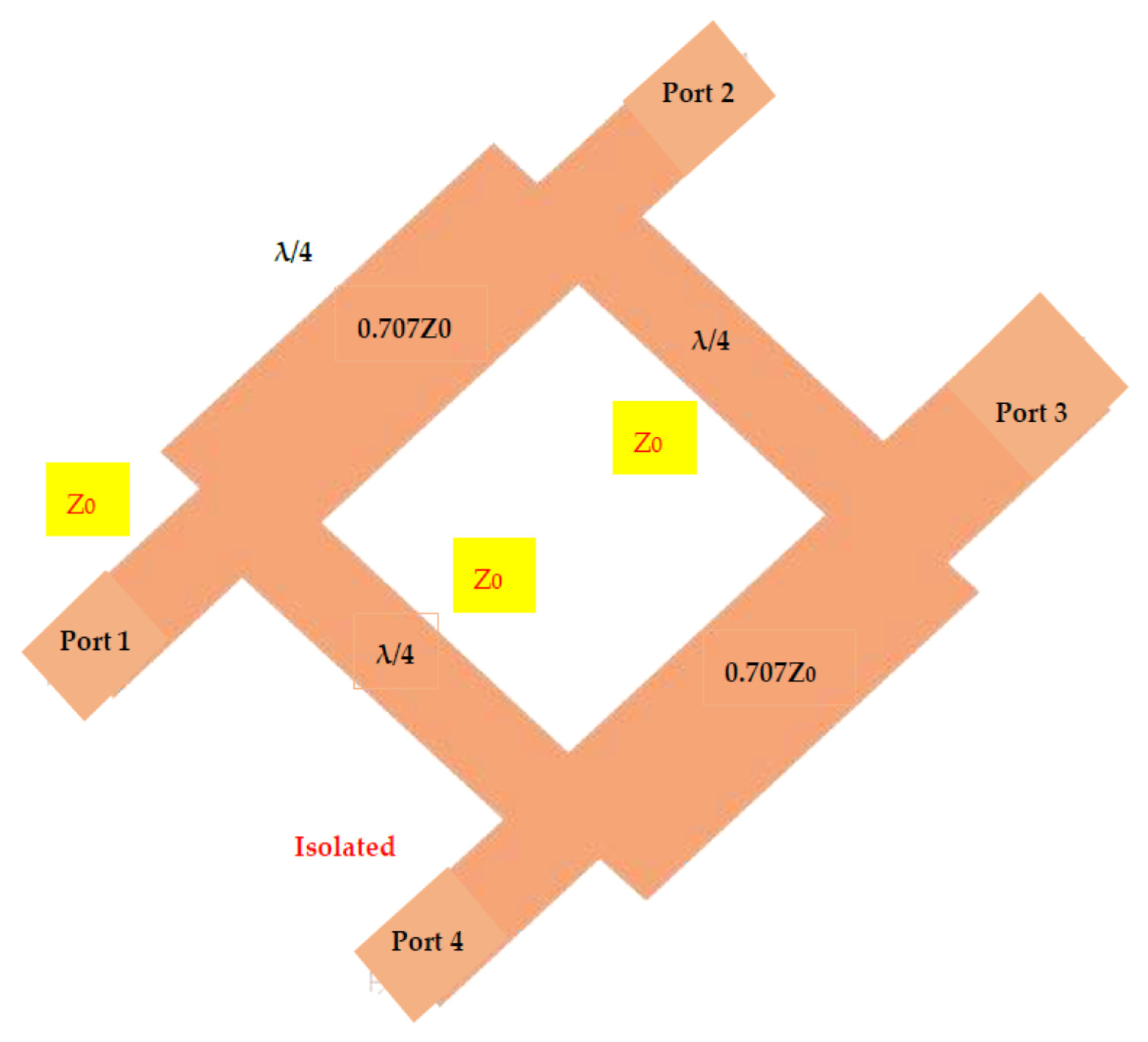
Electronics 11 00427 g003aElectronics 11 00427 g003b
Figure 4. Layout of the −3 dB branch line coupler.
Electronics 11 00427 g004
Figure 5. The branch line coupler reflection coefficient, S11.
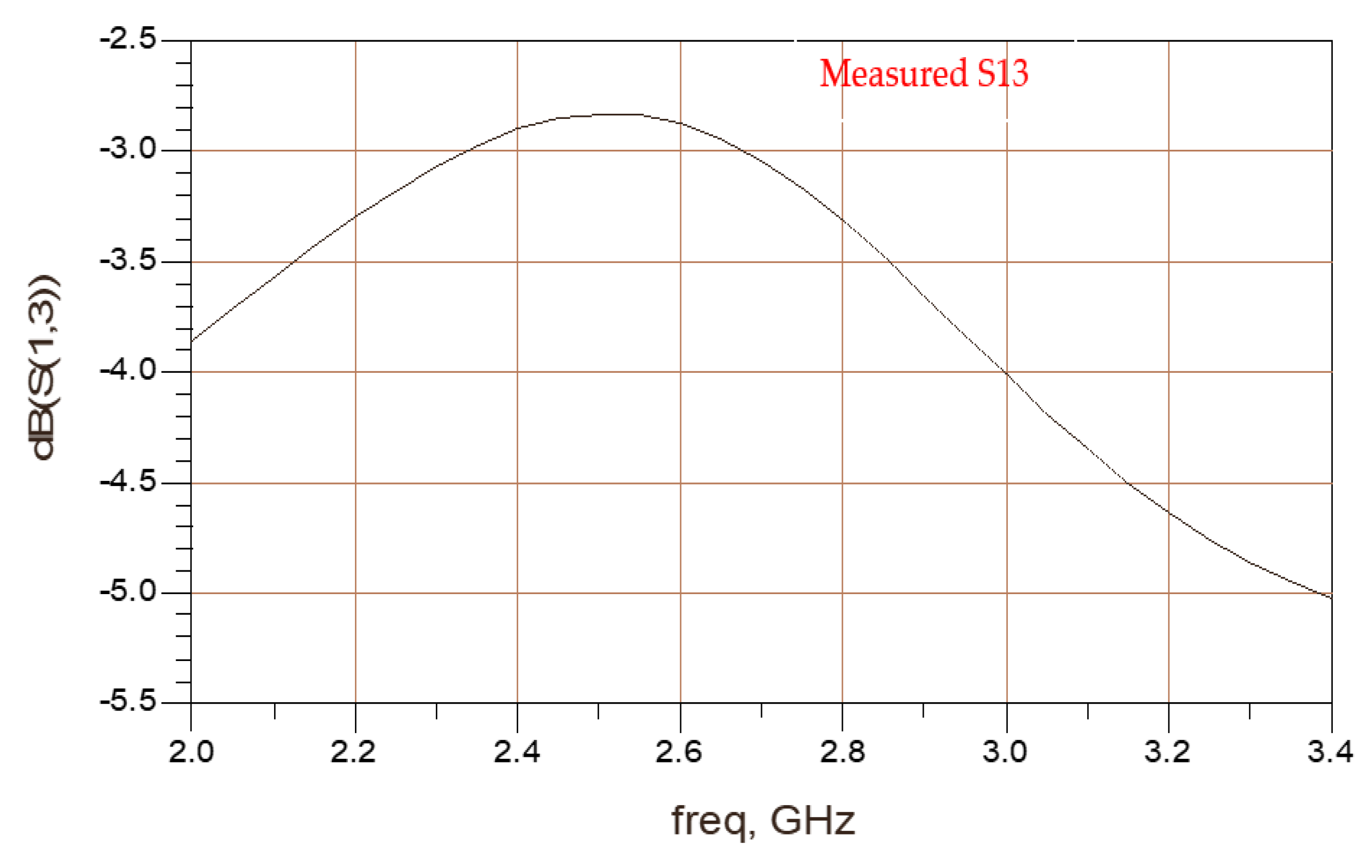
Electronics 11 00427 g005
Figure 6. The branch line coupler measured S13 transfer parameter.
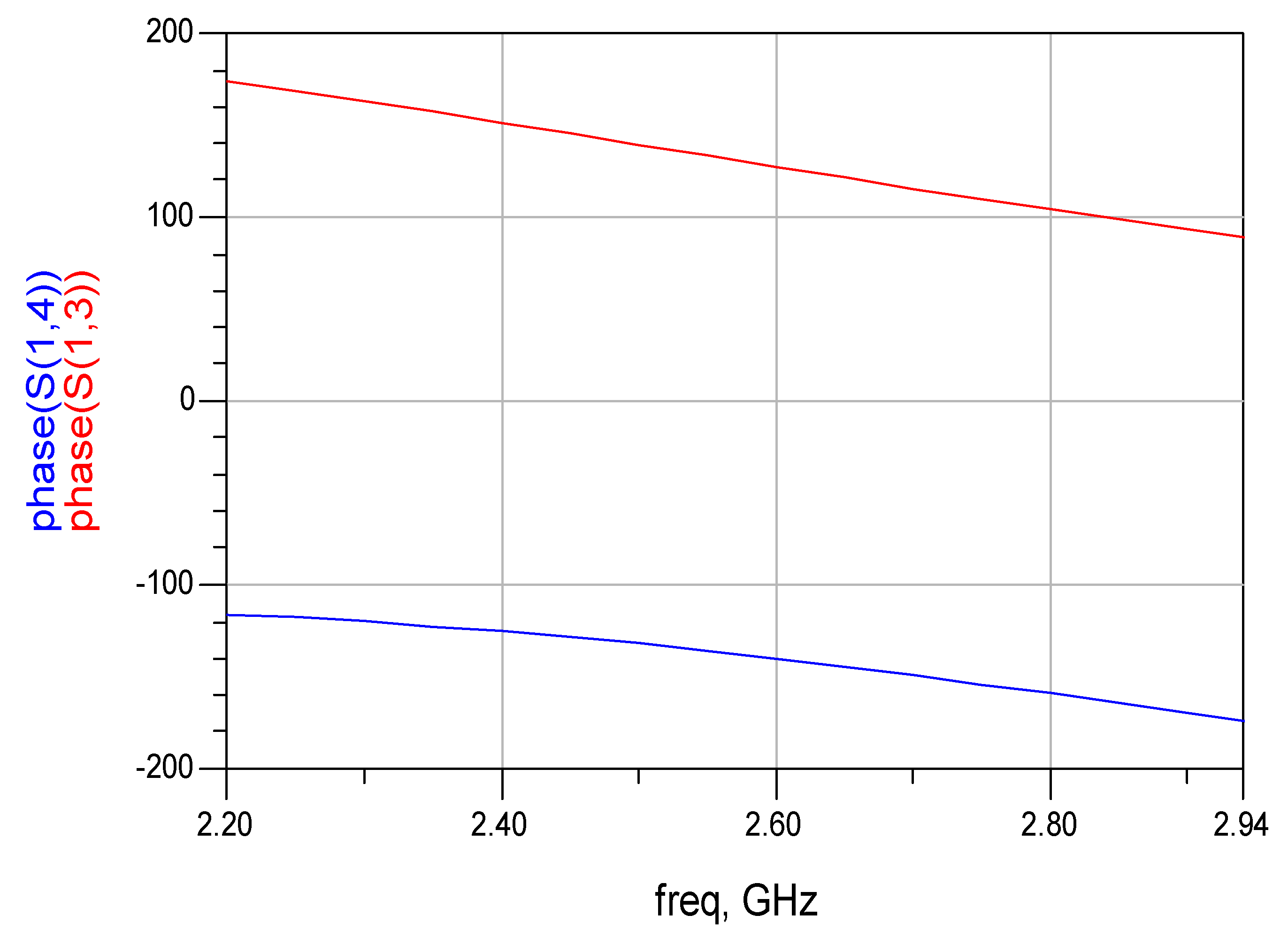
Electronics 11 00427 g006
Figure 7. The branch line coupler phase difference between S13 and S14 parameters.
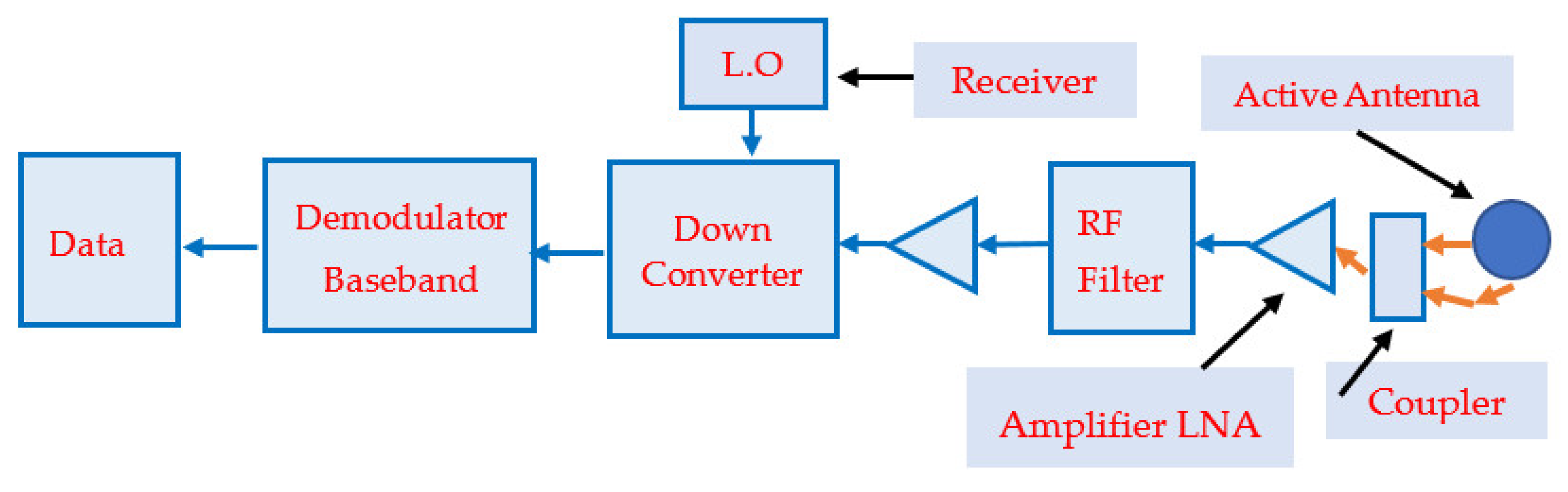
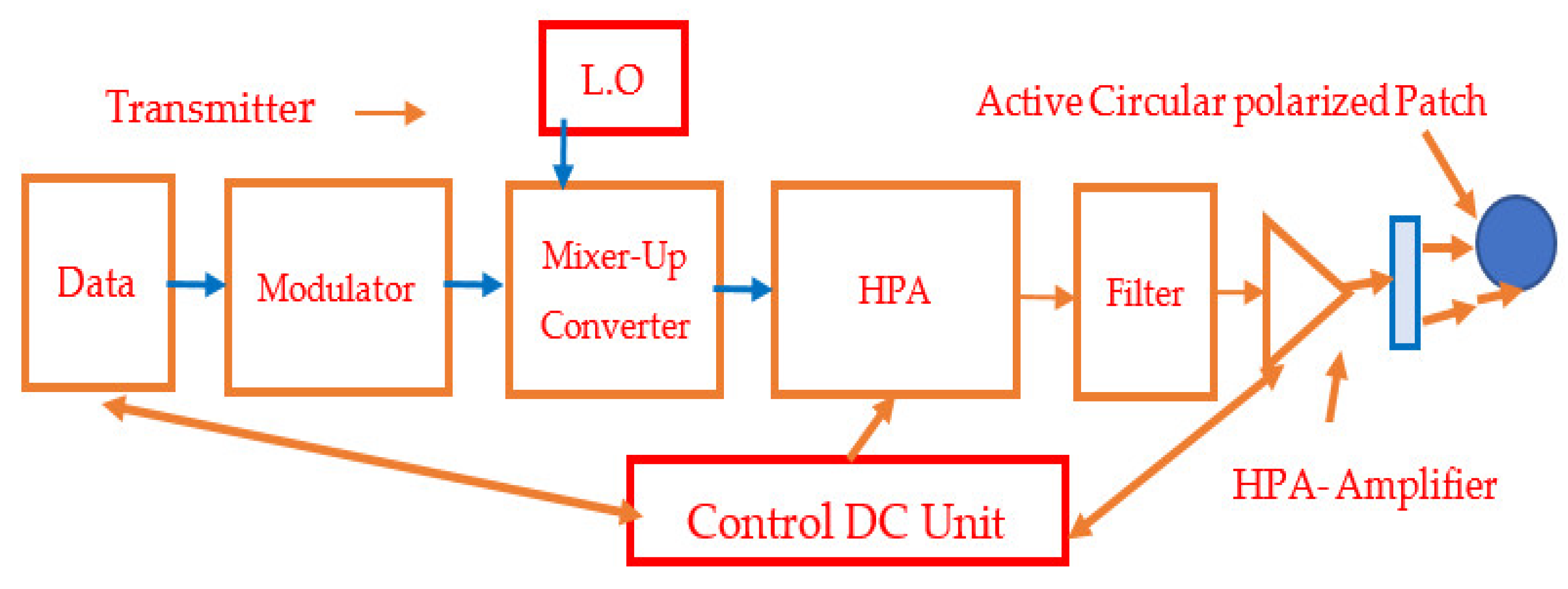
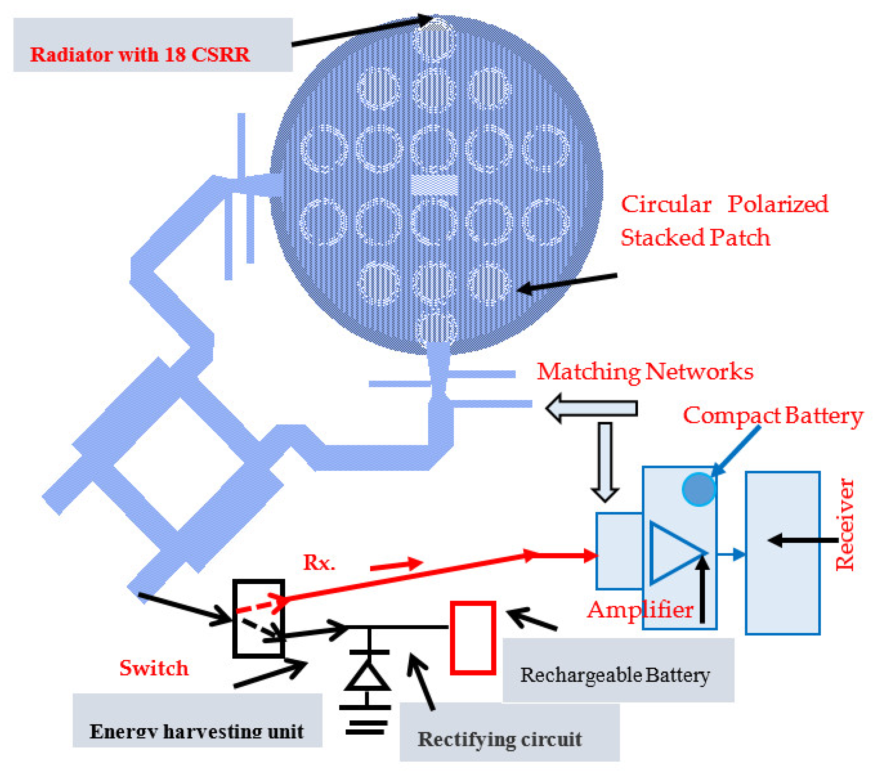
Electronics 11 00427 g007
Figure 8. Block diagram of a receiver with wearable active circular polarized antenna.
Electronics 11 00427 g008
Figure 9. Circular polarized wearable active receiving Sensor with energy harvesting unit.
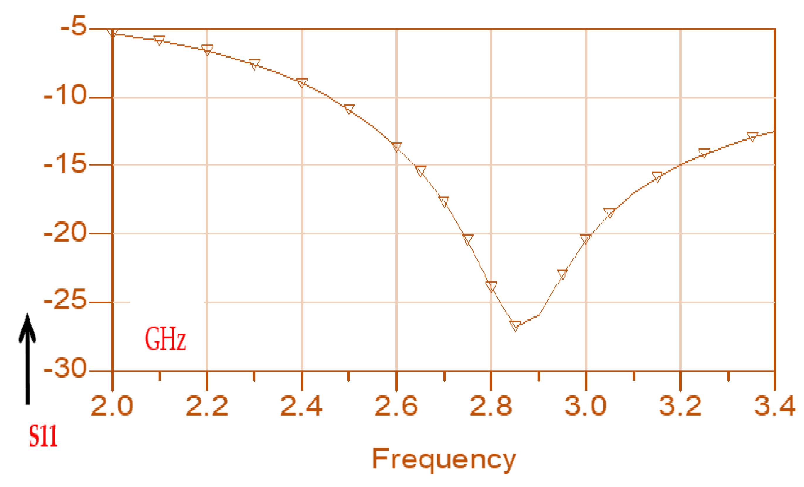
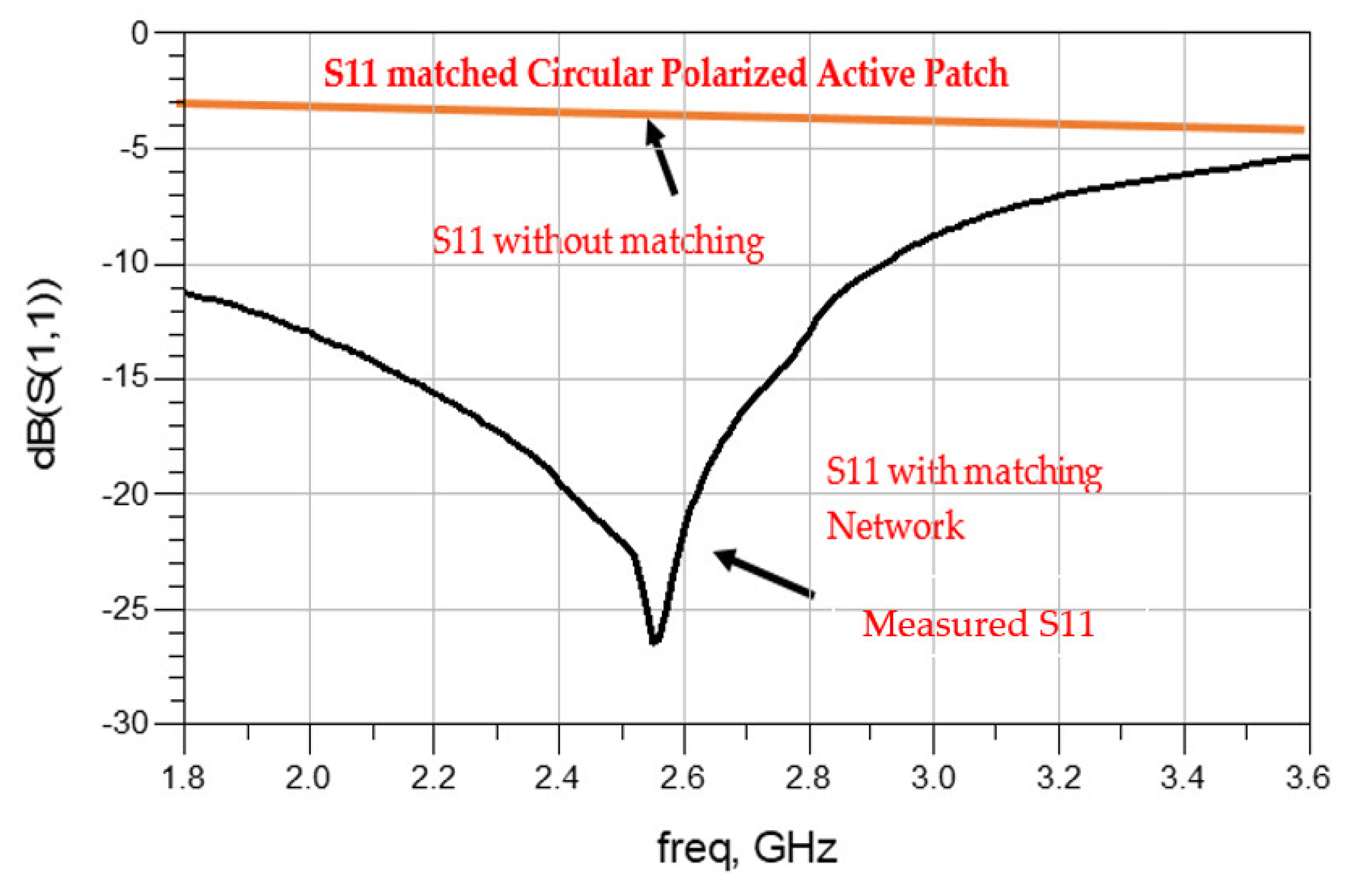
Electronics 11 00427 g009
Figure 10. Measured S11 of the Circular polarized active receiving antenna.
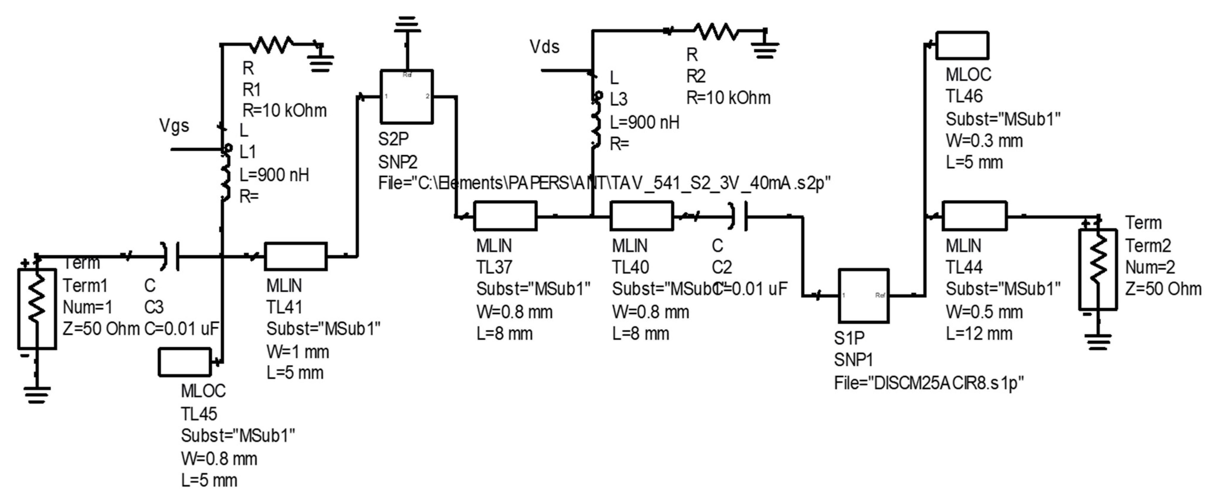
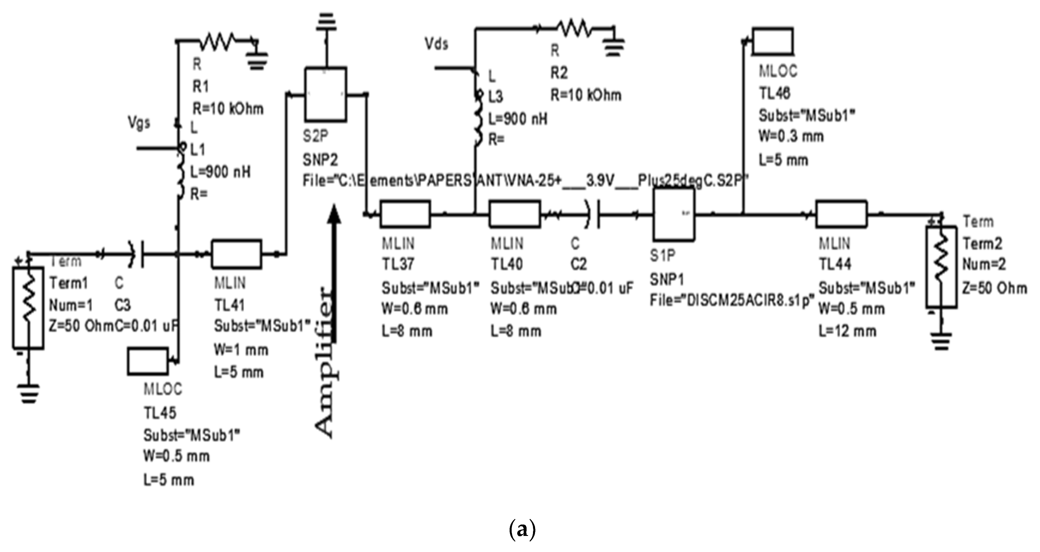
Electronics 11 00427 g010
Figure 11. Matching network of the circular polarized active receiving sensor.
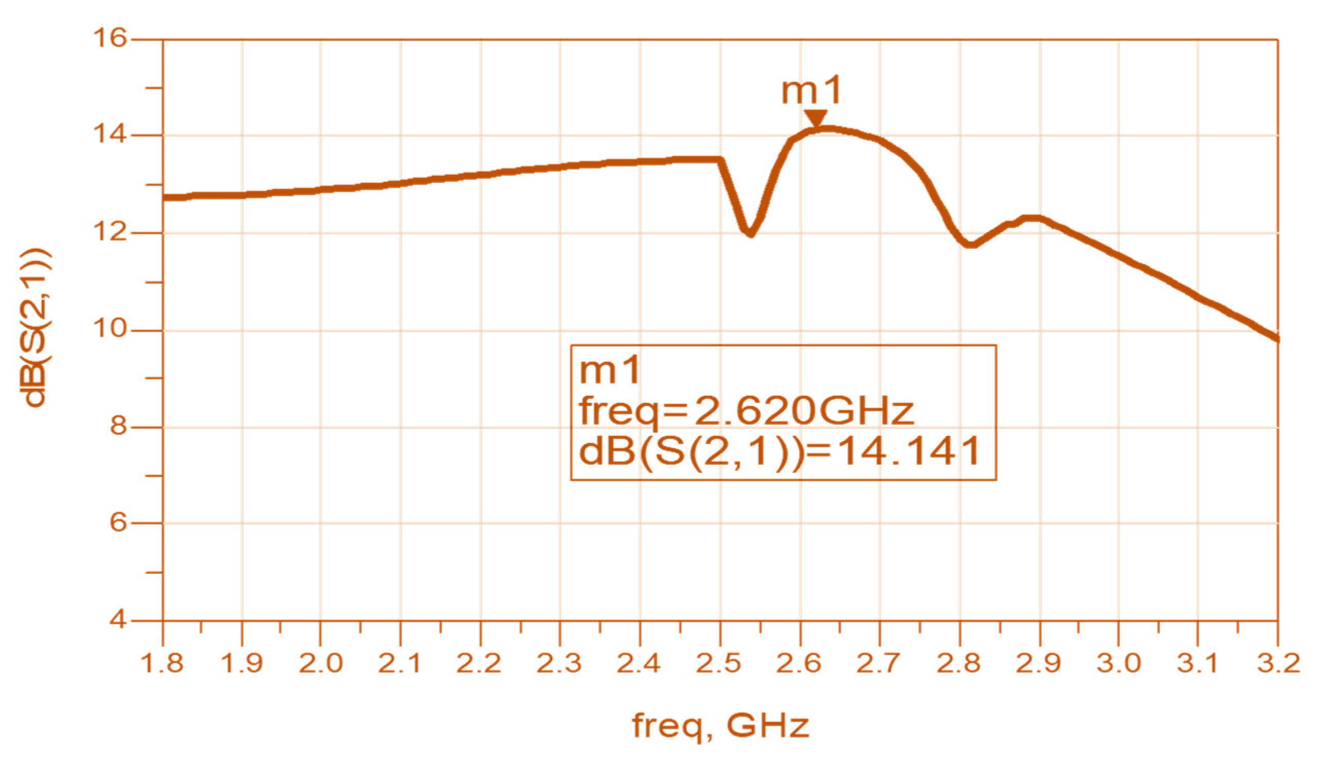
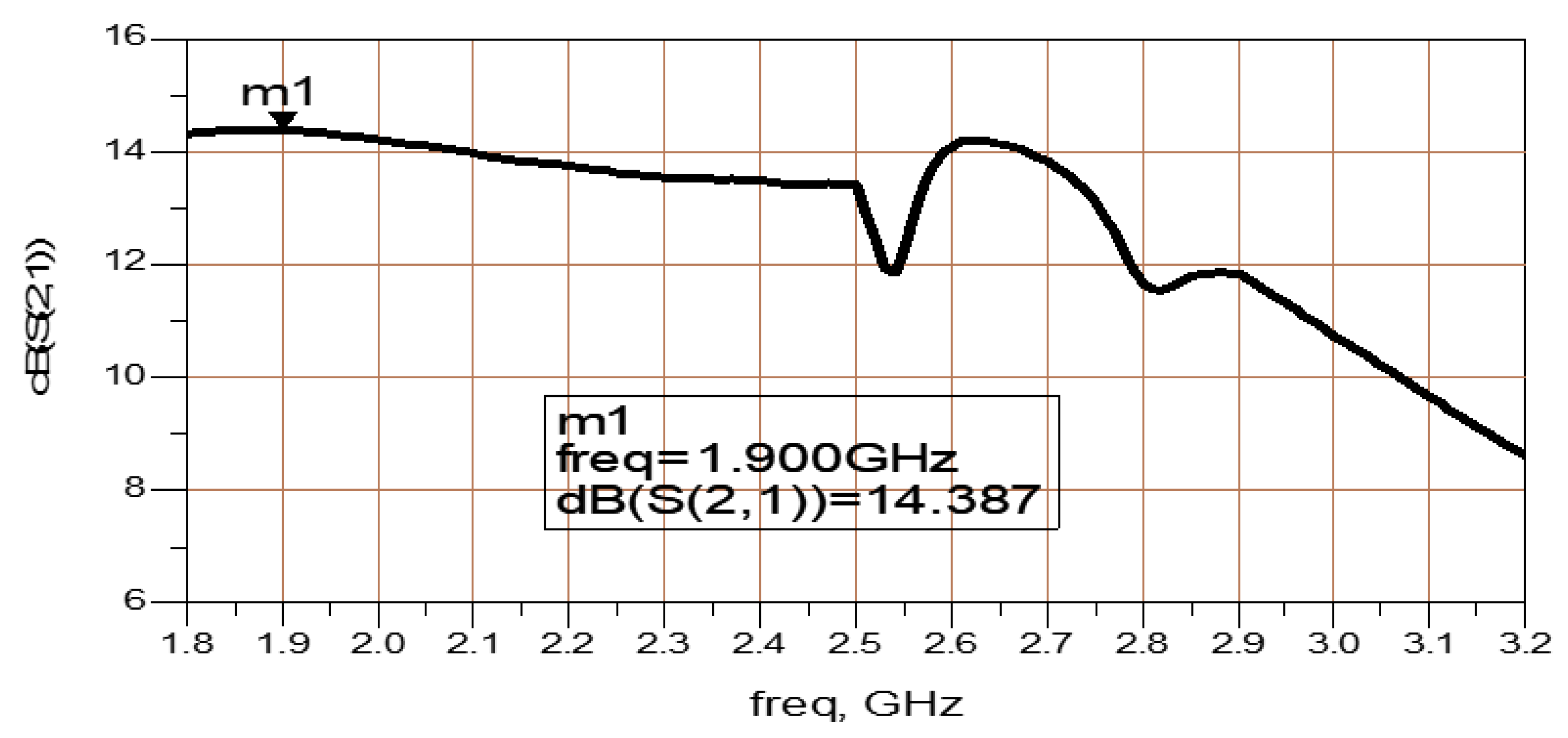
Electronics 11 00427 g011
Figure 12. Gain, S21, of the Circular Polarized Active Receiving Sensor.
Electronics 11 00427 g012
Figure 13. Transmitting channel block diagram with a wearable active transmitting sensor.
Electronics 11 00427 g013
Figure 14. Active Circular Transmitting Patch antenna for Internet of Things (IoT) and 5G Applications.
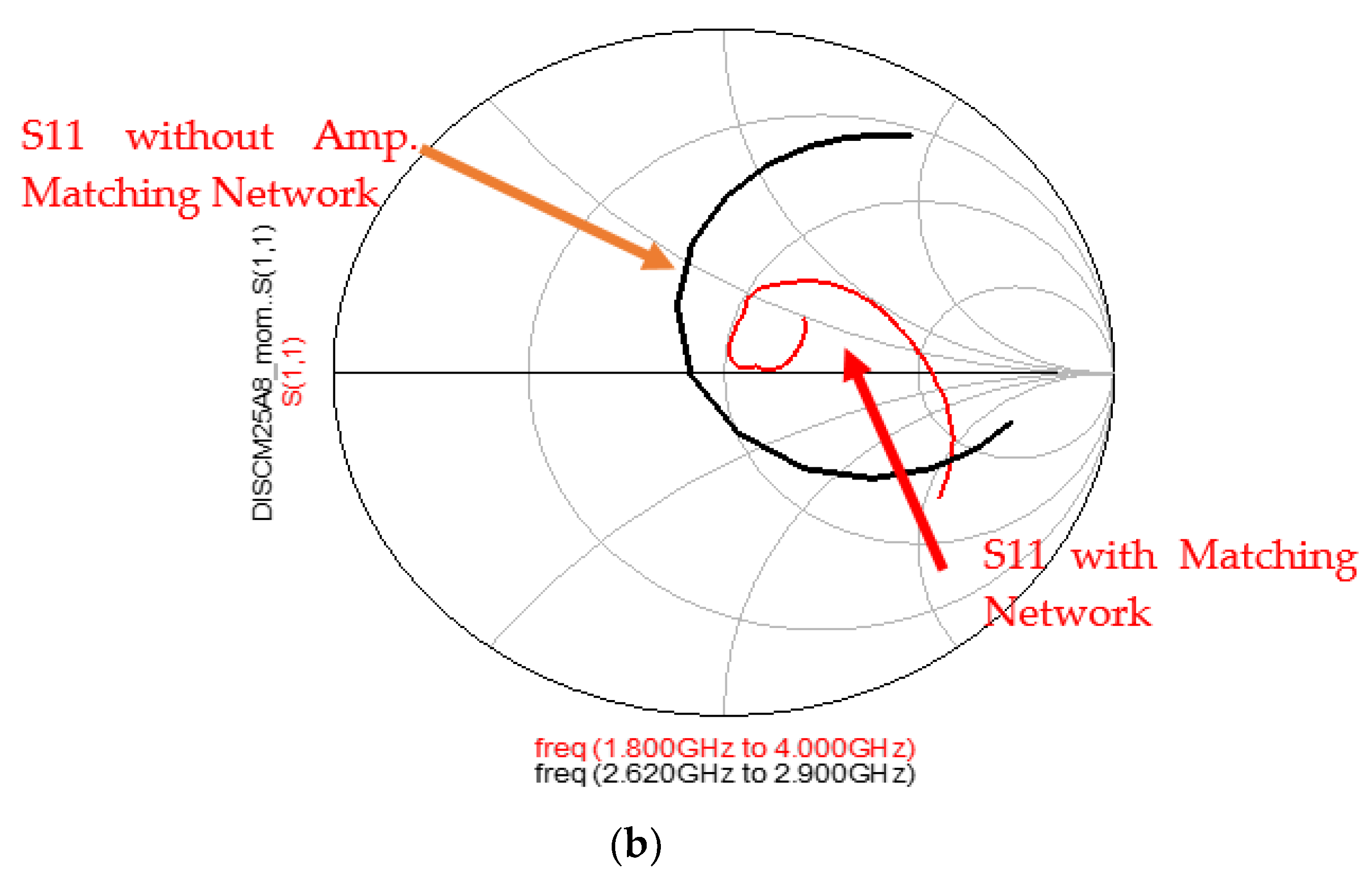
Electronics 11 00427 g014
Figure 15. Optimized Active Transmitting antenna: (a) Matching circuit; (b) S11 Smith chart diagram.
Electronics 11 00427 g015aElectronics 11 00427 g015b
Figure 16. Gain, S21, of the Active Transmitting Circular Polarized Antenna.
Electronics 11 00427 g016
Figure 17. Wideband Metamaterial Circular Polarized Sensor (a) Antenna; (b) CSRRs Photo.
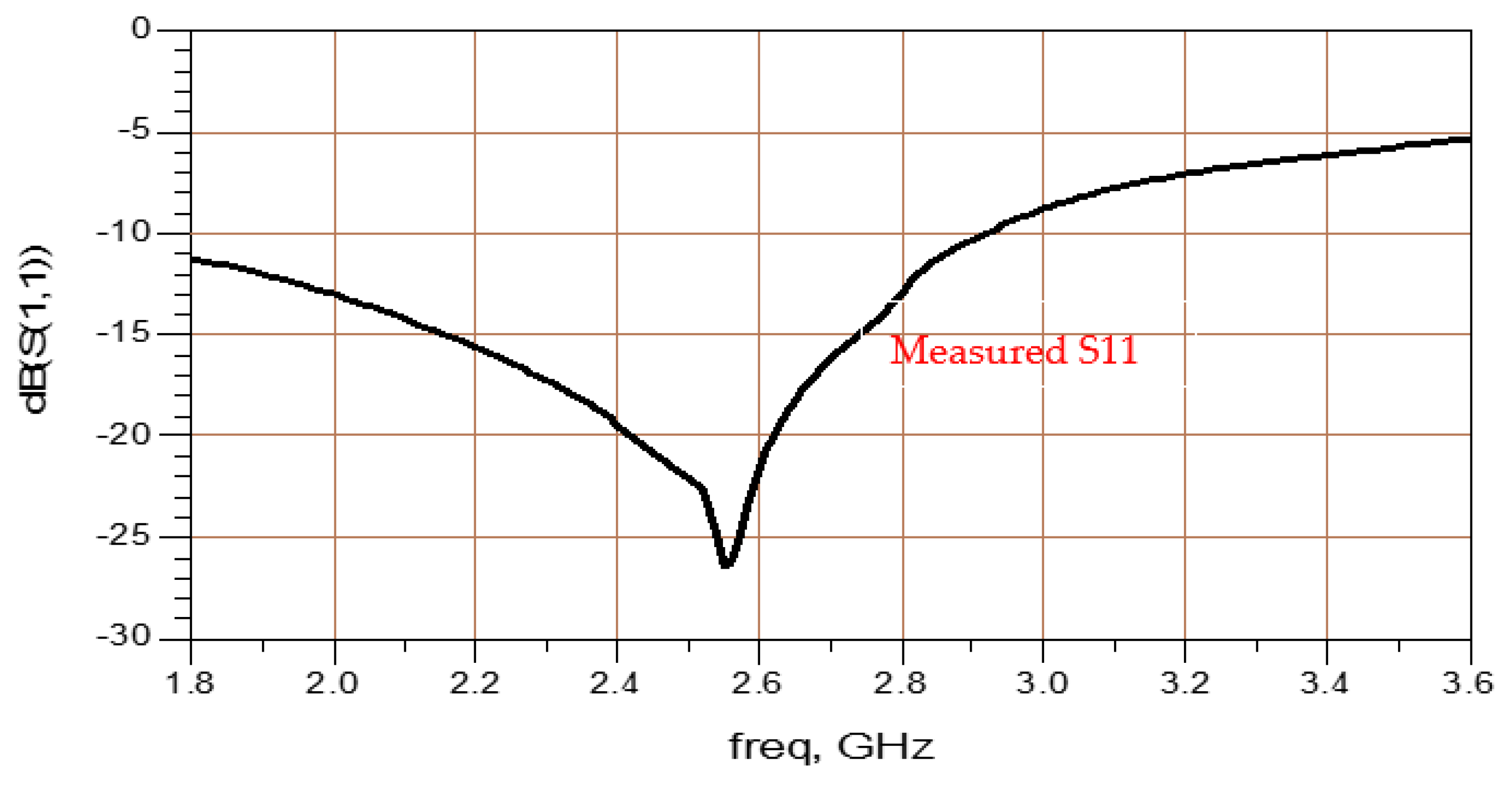
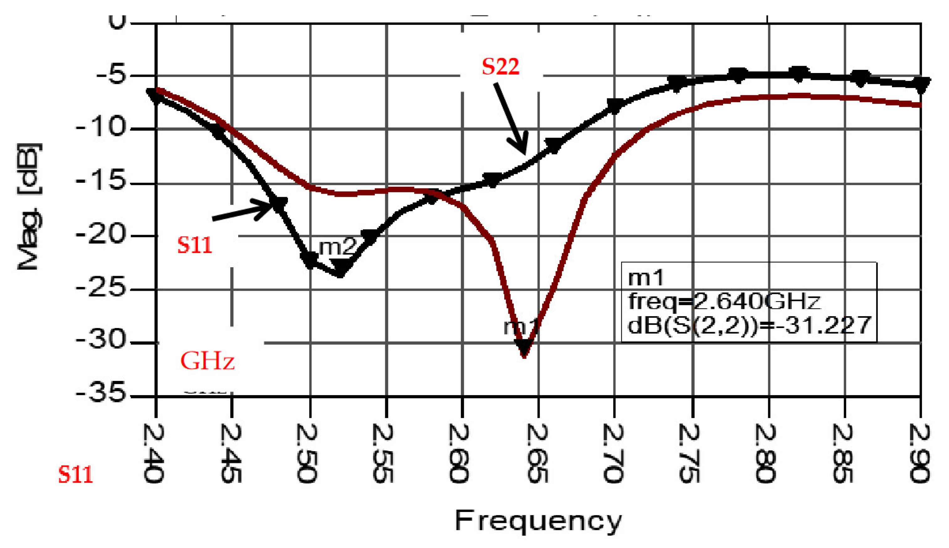
Electronics 11 00427 g017
Figure 18. S11 and S22 parameters of the circular polarized Patch Antenna with CSRRs.
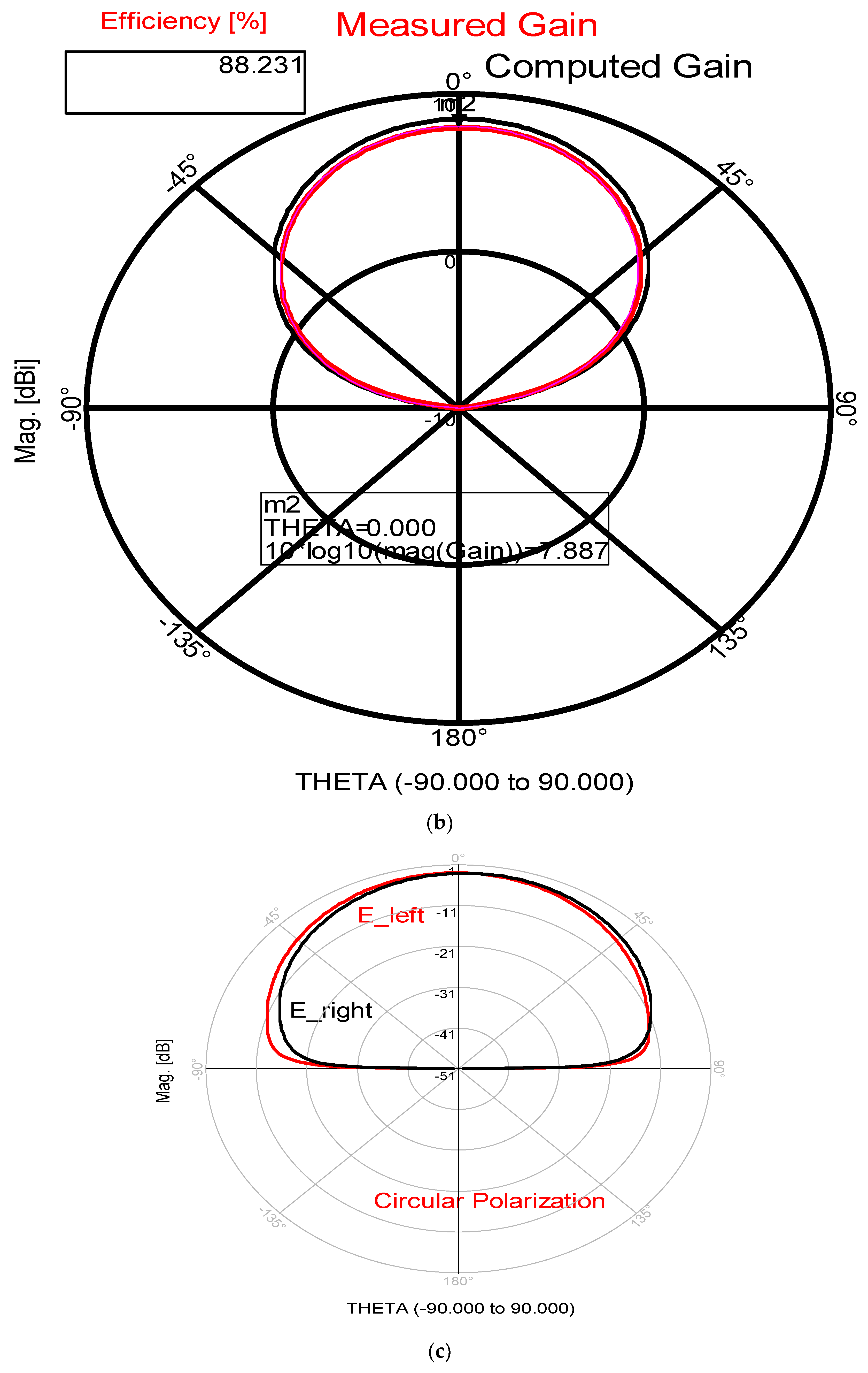
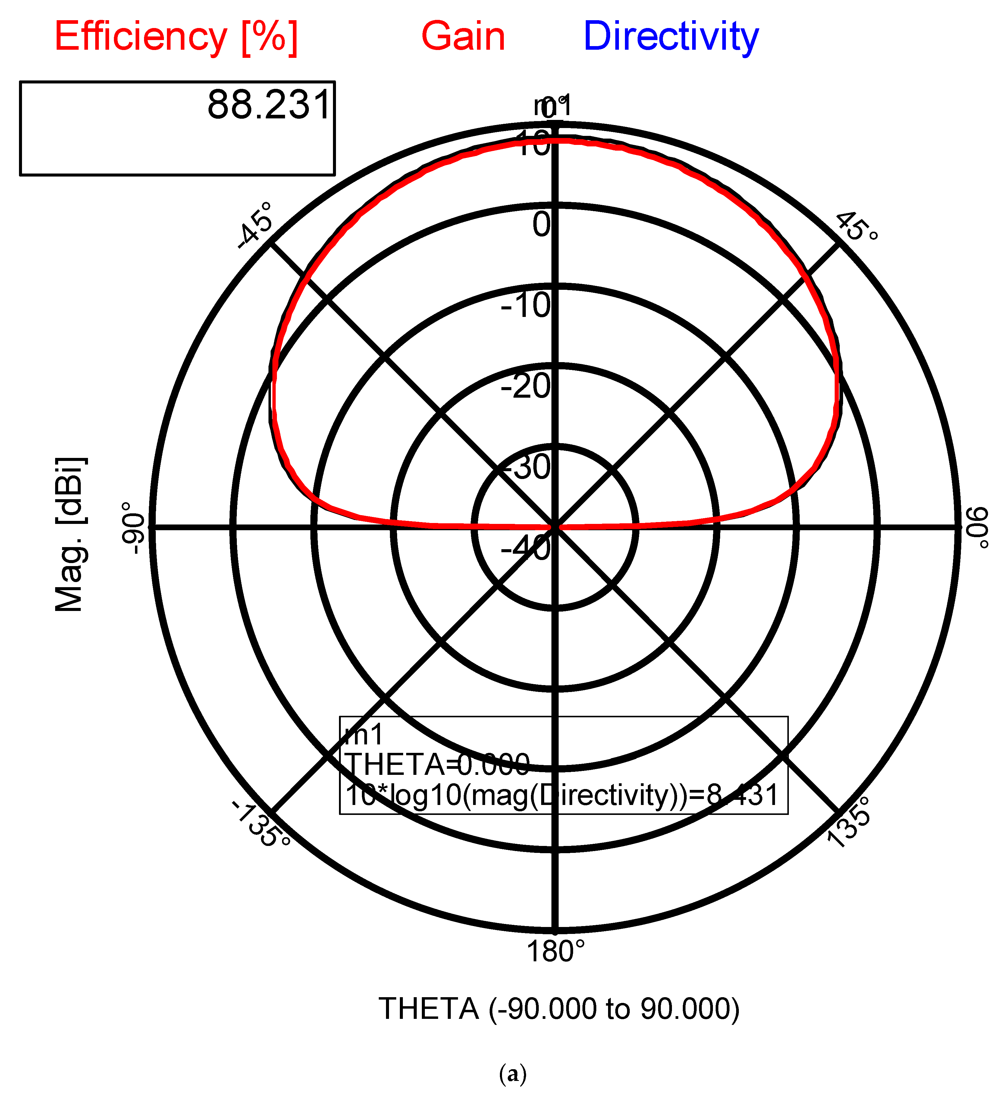
Electronics 11 00427 g018
Figure 19. Polar radiation pattern of the Circular Polarized patch with CSRR. (a) Radiation pattern; (b) Computed and measured gain. (c) The circularity of the circular polarized sensor.
Electronics 11 00427 g019aElectronics 11 00427 g019b
Figure 20. Metamaterial Circular Polarized Transceiver for IoT and medical applications.
Electronics 11 00427 g020
Figure 21. Measured S11 parameters of the circular polarized transmitting channel.
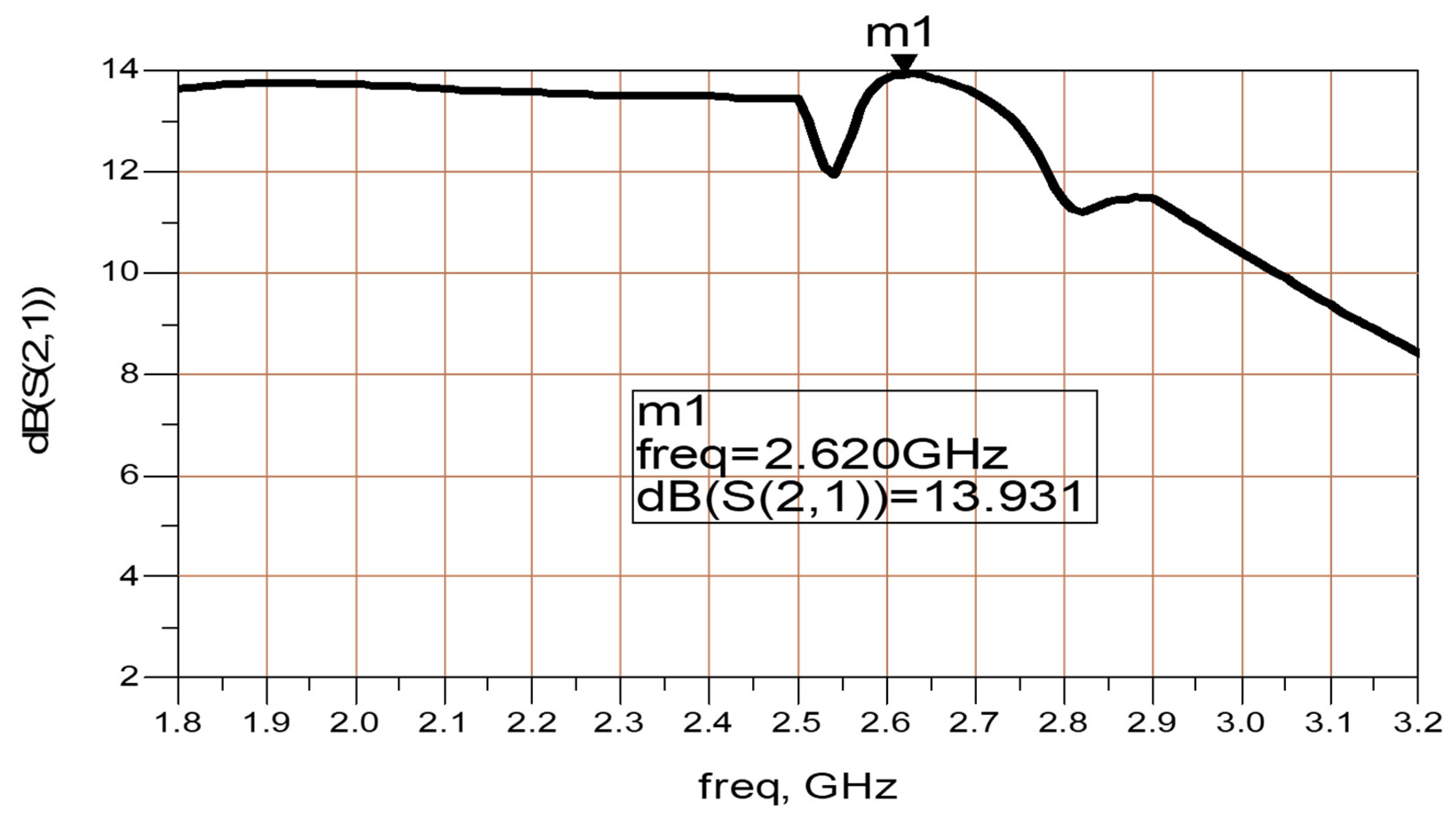
Electronics 11 00427 g021
Figure 22. S21 parameters of the circular polarized transmitting channel.
Electronics 11 00427 g022
Figure 23. S21 parameters of the circular polarized receiving channel.
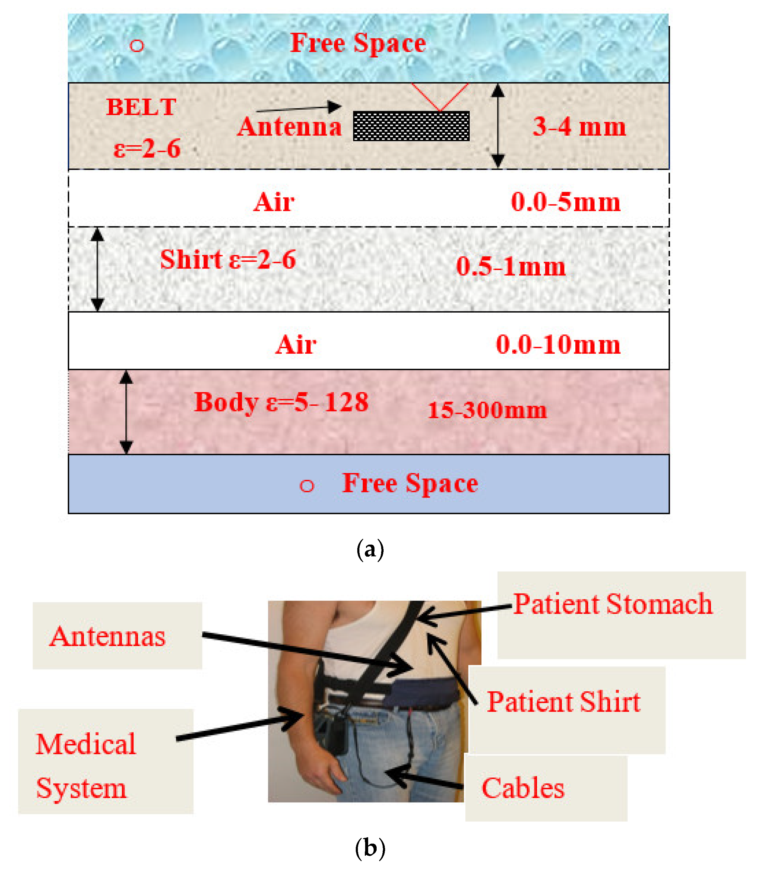
Electronics 11 00427 g023
Figure 24. (a) Model of human body tissues and antenna (b). A patient wearing a wearable healthcare sensor.
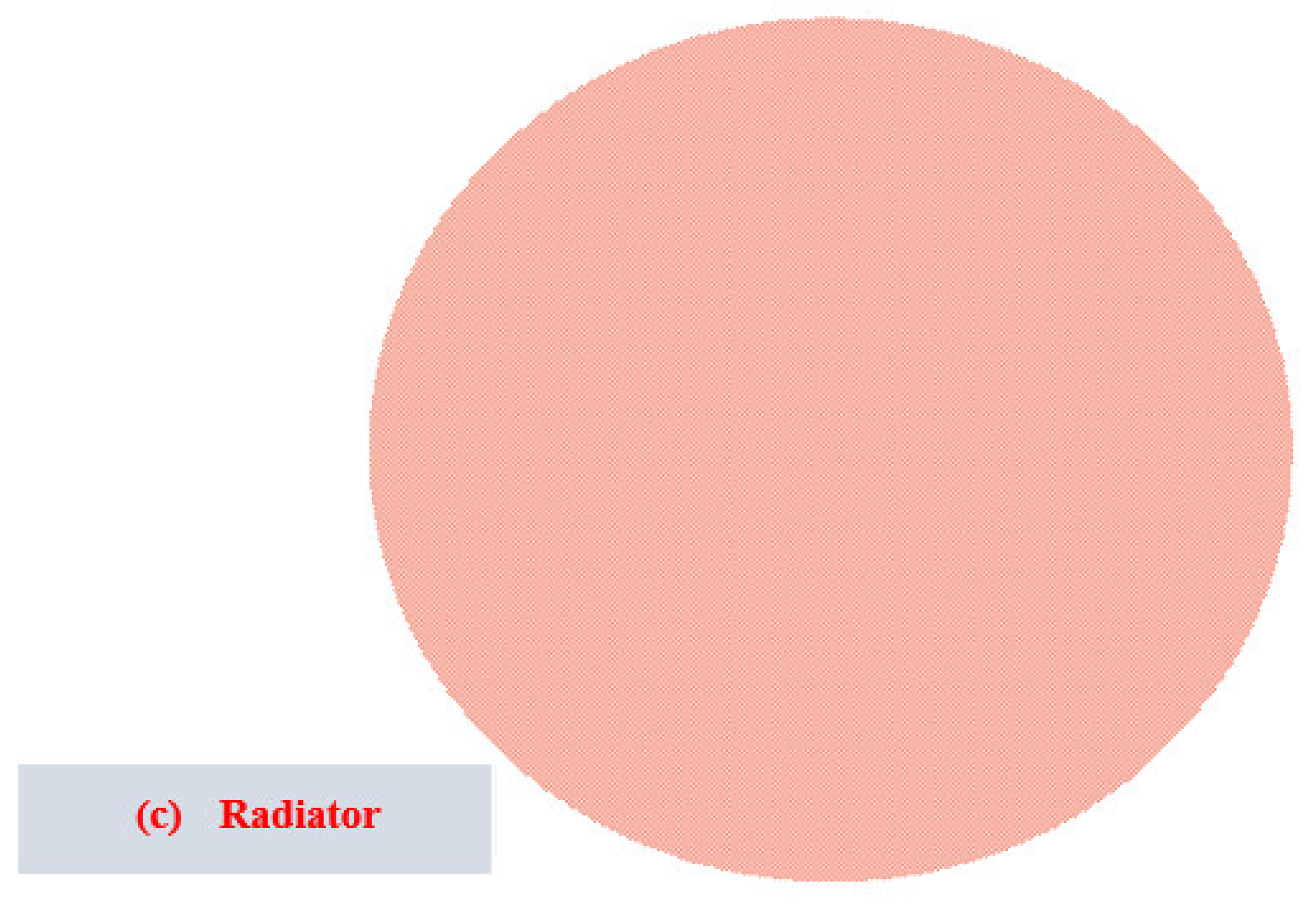
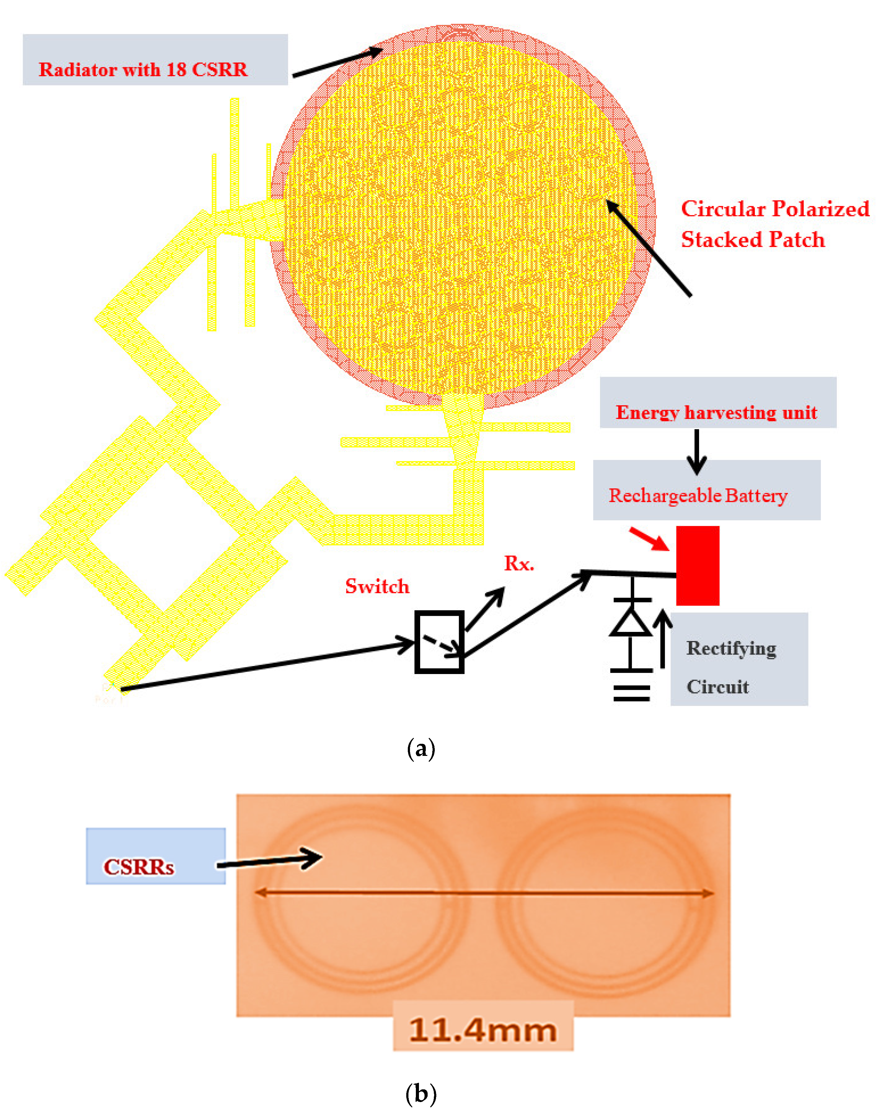
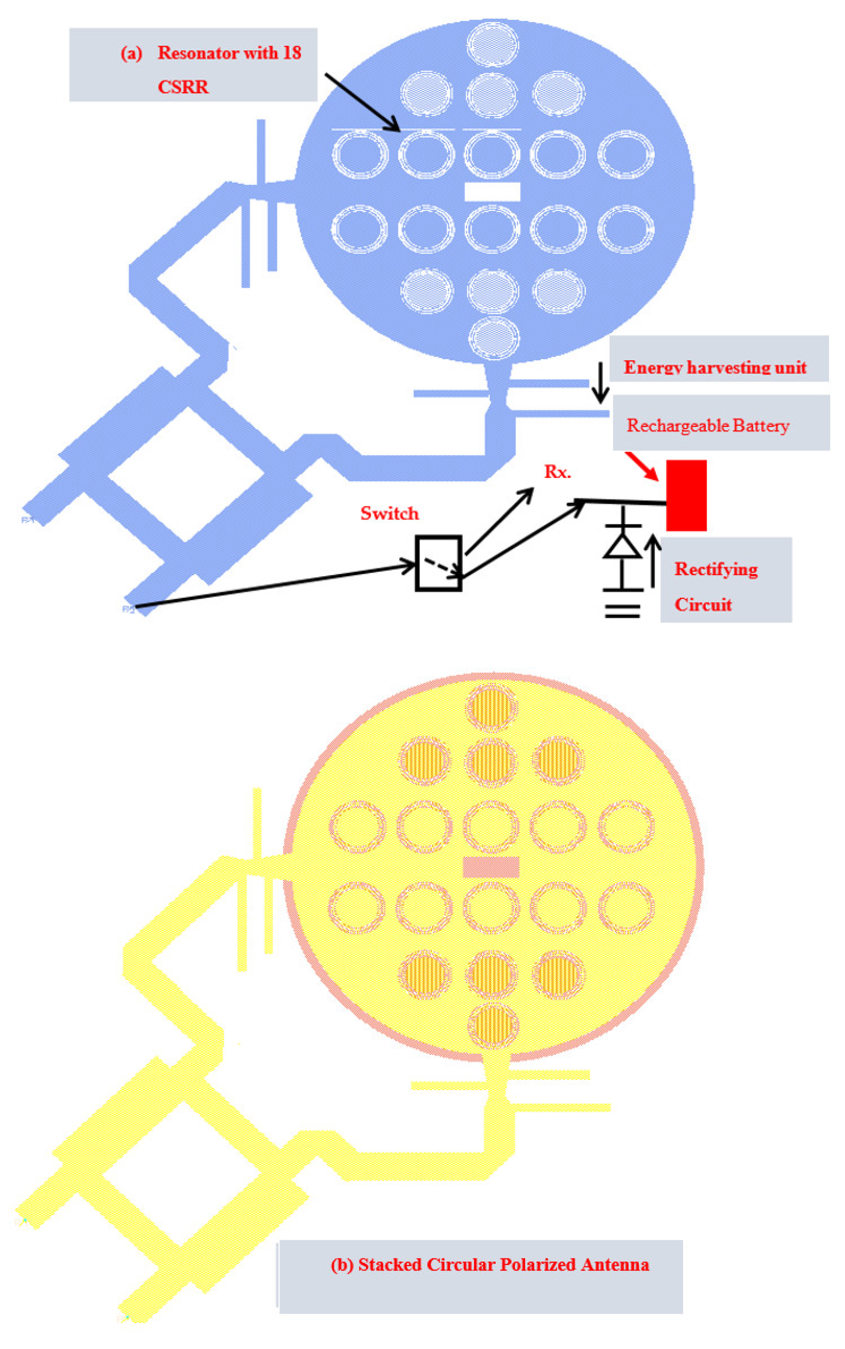
Electronics 11 00427 g024
Figure 25. Metamaterial Circular Polarized Patch with a harvesting unit, for IoT and medical applications. (a) Resonator with CSRRs (b) Stacked circular polarized patch (c) Radiating patch.
Electronics 11 00427 g025aElectronics 11 00427 g025b
Figure 26. Simulated and measured S11 of the wearable circular Polarized Antenna with CSRR.
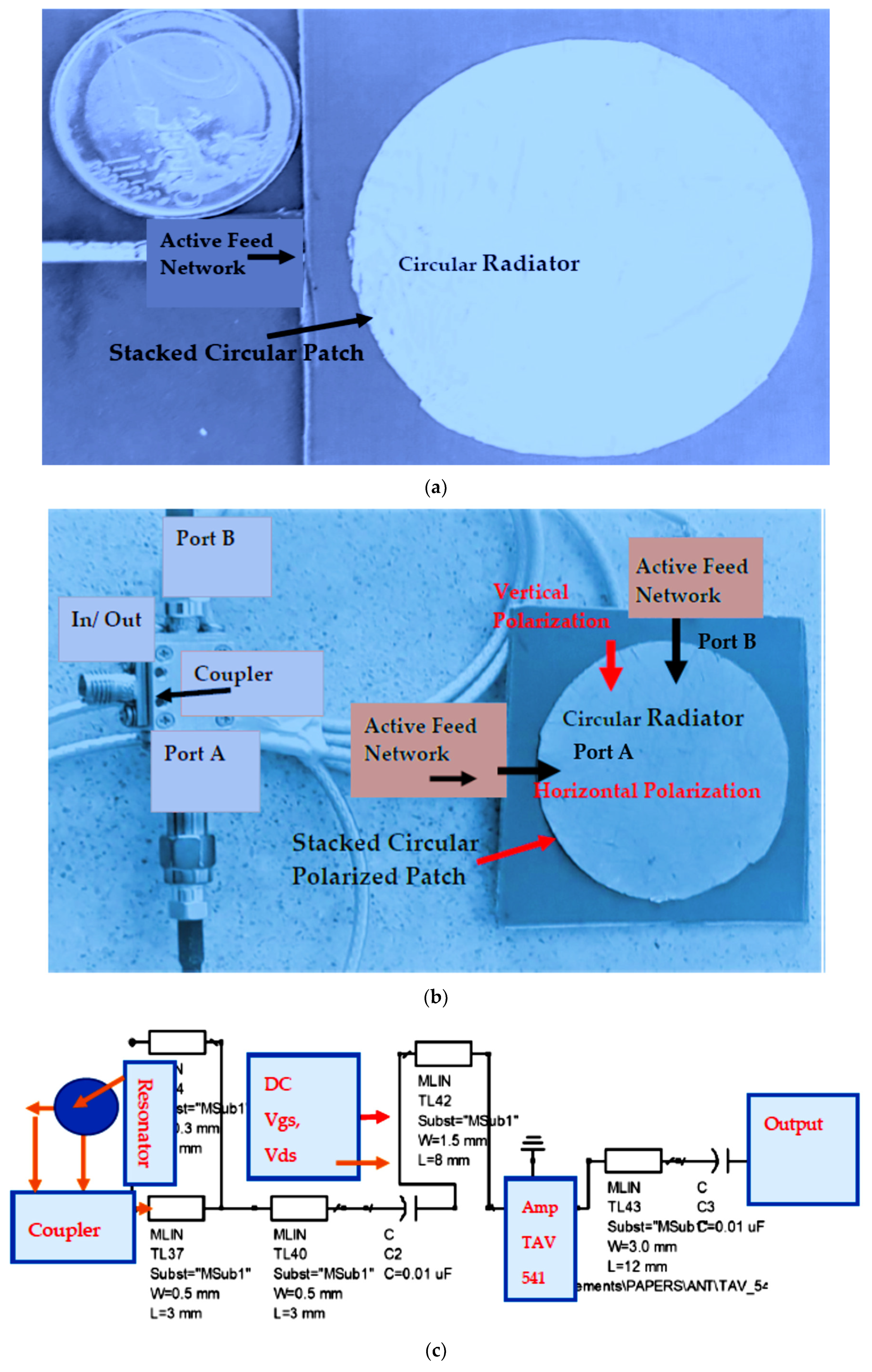
Electronics 11 00427 g026
Figure 27. (a) Photo of the lab module of the Active Circular Stacked antenna (b) A photo of the lab module of the Active Circular Polarized patch (c) Layout of the Active Antenna modules analysis.
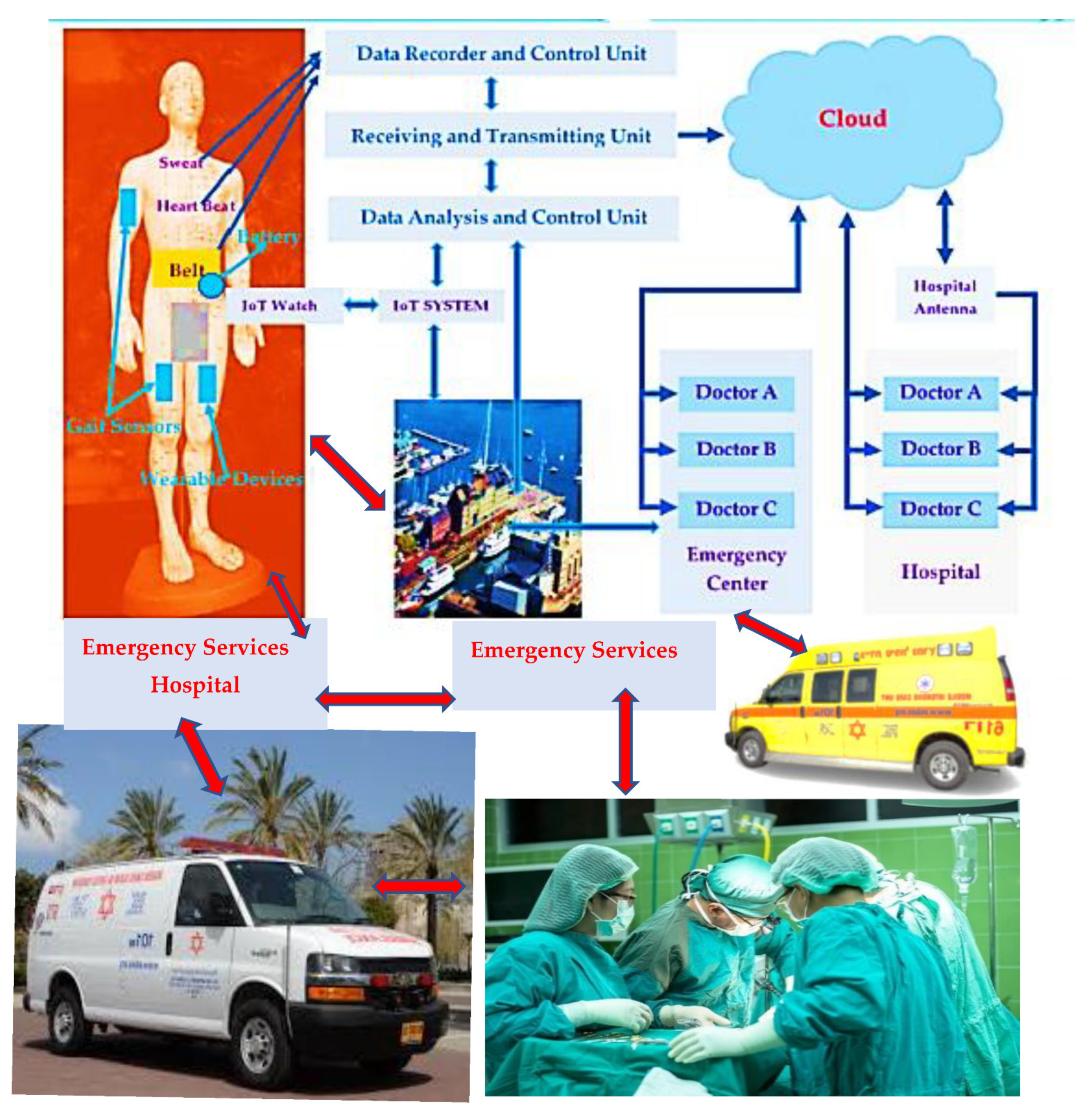
Electronics 11 00427 g027
Figure 28. Smart City IoT, and healthcare monitoring systems with wearable sensors and WBAN Networks.
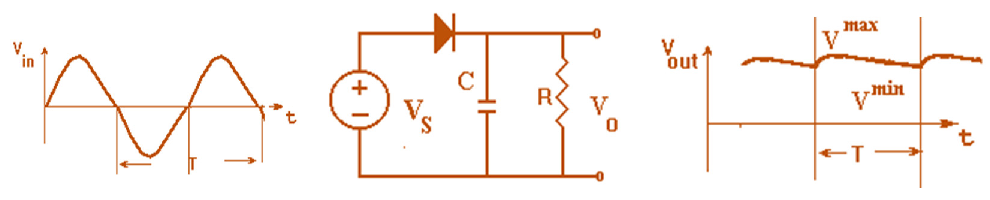
Electronics 11 00427 g028
Figure 29. Voltage rectifier, half wave, with a shunt capacitor.
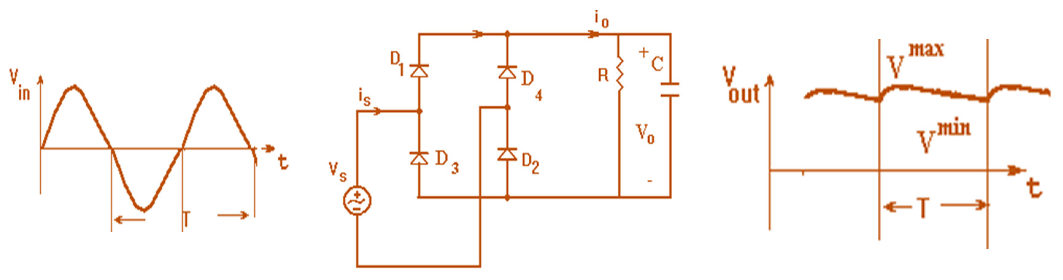
Electronics 11 00427 g029
Figure 30. Diode Bridge rectifier, full wave, with a shunt capacitor.
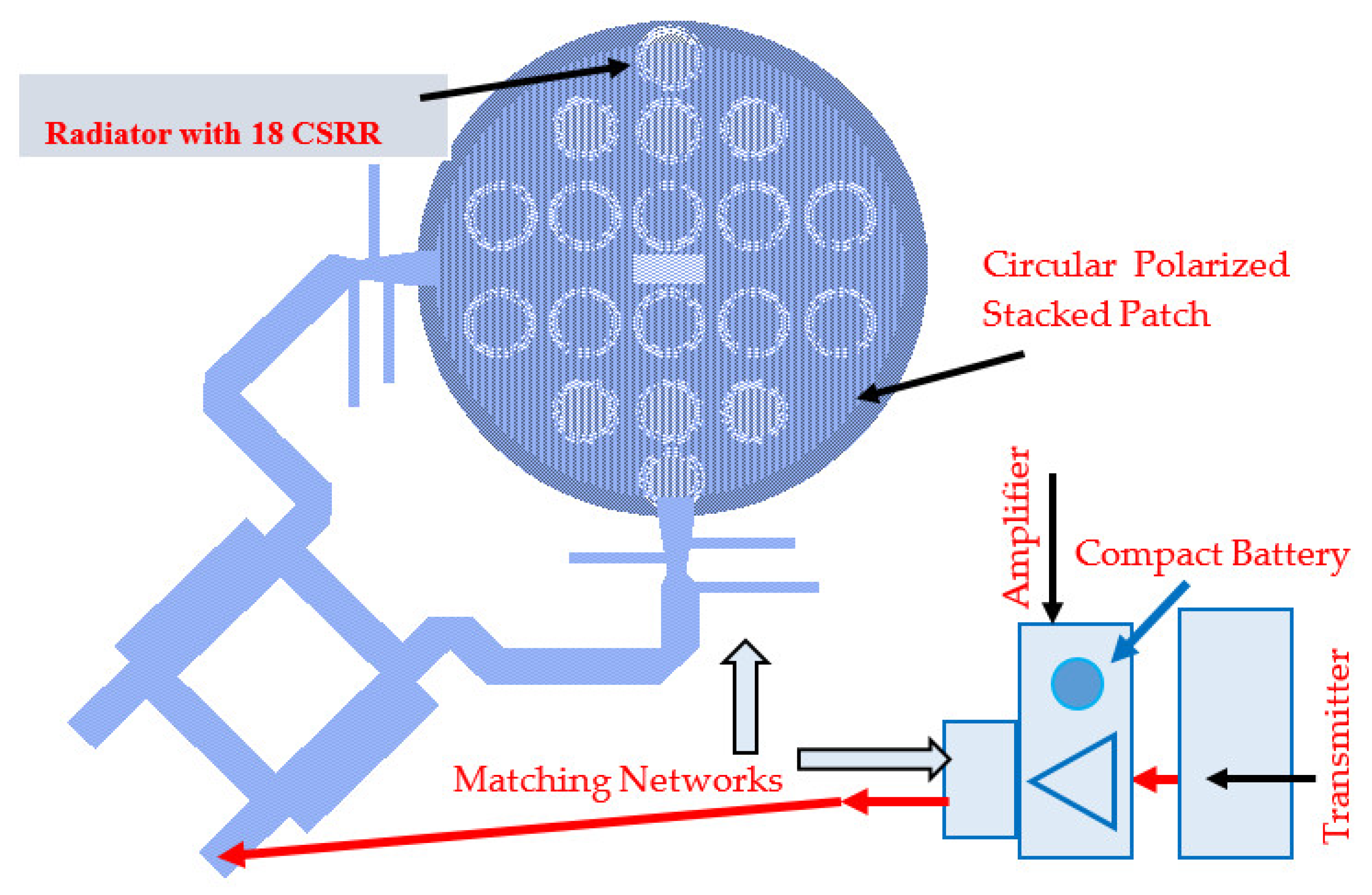
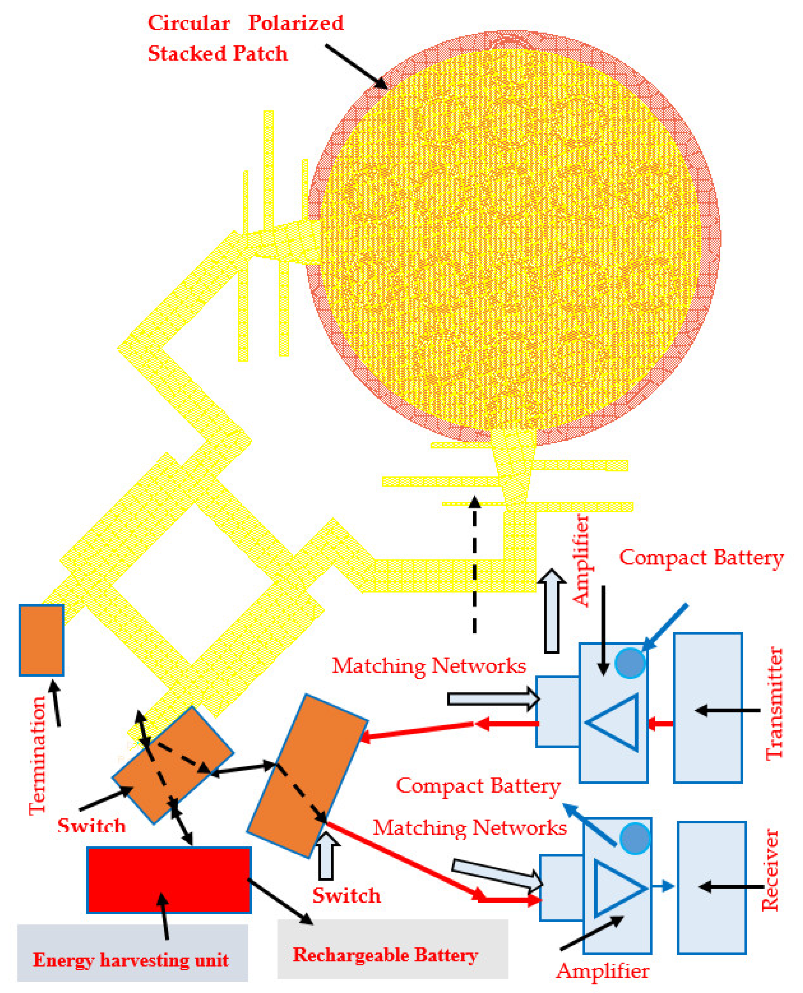
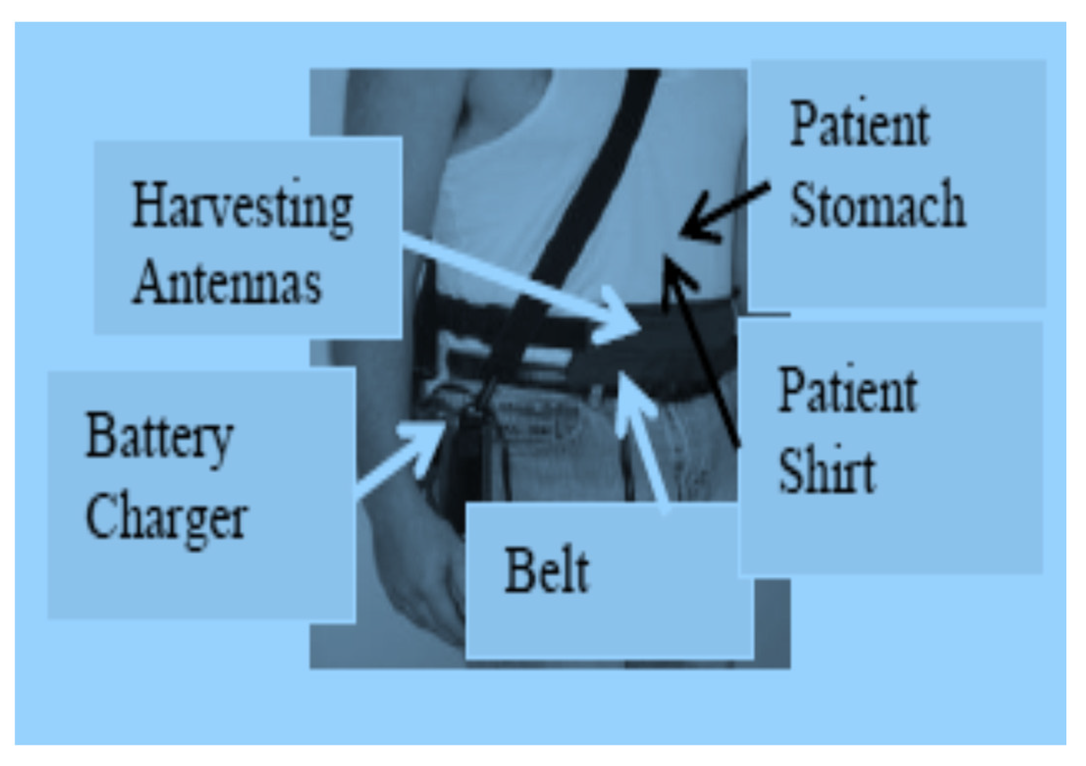
Electronics 11 00427 g030
Figure 31. Wearable RF Medical Sensors with Energy Harvesting unit for IoT, 5G, and Healthcare Applications.
Electronics 11 00427 g031
Table 1. Small Antennas Gain and efficiency Comparison, 1970–2021.
Antennas Type1970–1980 [1,2]1981–1995 [1,2]1996–2010 [3]2011–2021 [2]
Gain dBEfficiency %Gain dBEffic. %Gain dBEffic. %Gain dBEffic. %
Printed dipole2302.550370480
Patches2.5503703.570480
Stacked patches--6807857.585
Metamaterial Antennas----4508.590
Metamaterial with strips------5.5–7.590
Fractal Antennas--2504.570580
Table 2. Small Antennas Bandwidth Comparison, 1970–2021.
Antennas TypePrinted DipolePatchesStacked PatchesMetamaterial AntennasMetamaterial with StripsFractal Antennas
Antenna bandwidth %, 1970–1980 [1,2]52----
Antenna bandwidth %, 1981–1995 [1,2]5310--2
Antenna bandwidth %, 1996–2010 [3]551210-5
Antenna bandwidth %, 2011–2021 [2]5515505010
Table 3. Branch line coupler design.
ImpedanceW mmεeL (λ/4) mm
Z0 = 50 Ω33.414.8
Z0 = 35.4 Ω5.13.614.4
Table 4. Specification of the S band Low Noise Amplifier.
ParameterSpecificationRemarks
Frequency0.4–3 GHz-
Gain at 1.9 GHz18 dBVds = 3 V
N.F at 1.9 GHz0.5 dB-
P1dB at 1.9 GHz19.0 dBm-
OIP3 at 1.9 GHz33.5 dBm-
Max Input power17 dBm-
Vgs0.50 V-
Vds3 VIds = 60 mA
Supply voltage±5 V-
PackageSurface Mount-
Operating Temperature−40 °C–80 °C-
Table 5. LNA noise parameters at S band.
LNA Noise Data
F-GHzN. FMINN11XN11Yn
1.400.240.35076.500.036
1.900.300.370100.930.03
2.000.320.372106.010.03
2.400.400.380125.790.03
3.000.490.400153.930.036
3.900.650.430−167.300.06
4.500.720.460−145.550.09
Table 6. Comparison of simulated and measured results of circular microstrip patches [15].
AntennaFrequency (GHz)Bandwidth %VSWRComputed Gain dBiMeasured Gain dBi
Circular patch [15]2.6222:14.44.1
Circular patch with CSRR [15]2.52–2.6882:17–7.67–7.9
Circular polarized patch with CSRR2.5–2.9202:17.5–8.37.2–8
Active Circular Rx. Patch [15]2.4–2.8252:112–1411.5–13.8
Stacked circular patch with CSRR [15]2.6–2.882:17–8.47.2–8.5
Active Stacked Circular Patch [15]2.4–2.8252:112–1412–15
Active Circular Polarized Patch2.4–2.8402:110–1410–15
Table 7. Specification of the High-power S band surface mount amplifier (HPA).
ParameterSpecificationRemarks
Frequency range1–4 GHz-
Gain at 2.5 GHz15 dBVds = 5 V
N.F at 2 GHz5.5 dB-
P1dB at 2 GHz18.0 dBmIds = 85 mA
OIP3 at 2 GHz29 dBm-
Input power10 dBmMaximum
Vgs0.50 V-
Vds4–5 V-
Ids60–85 mA-
Bias voltage±5 V-
Temperature range−40 °C–85 °COperating
Table 8. S band High-power amplifier S parameters.
F-GHzS11 dBS11°S21 dBS21°S12 dBS12°S22 dBS22°
1.56−12.3137.617.5134.967.8−11.2−18.992.4
1.6−12.8134.318.3123.3−44.2−93.4−18.9113.7
1.8−14.3101.217.983−43−86.3−2269.5
2−16.561.817.343.5−40.494.6−276.42
2.16−18.522.116.812.9−38−105.5−27.8−70.2
2.4−19.4−53.915.7−31.8−36−128−22.2−147.2
2.56−17.799.715−60−34.6−145.6−19.3−179.4
2.7−15.713114.3−84.3−33.8−160.3−17.5158.1
2.86−13.715913.5−111.1−33−177.7−16134.7
3−12.2179.112.7−134.1−32.4167.415.2116.3
3.18−10.9158.111.5−164.9−29.4133.8−16.1176.4
3.4−9.3129.3310.3156.5−28.9107.7−16.05146.9
3.6−8.5109.59.4128.2−28.487.9−15.9128.5
Table 9. Electrical parameters of human body tissues [16,17].
TissueParameter440 MHz600 MHz1 GHz1.25 GHz
Fat tissuesσ0.0470.050.0540.06
ε5.005.004.724.55
Stomach tissuesσ0.710.750.960.98
ε42.741.4039.6639.00
Bloodσ1.761.781.911.99
ε57.256.555.4055.00
Skinσ0.580.60.630.77
ε41.640.4540.2539.65
Lung tissuesσ0.270.270.270.28
ε38.438.438.438.4
Kidney tissuesσ0.900.900.900.91
ε117.45117.45117.45117.45
Colon tissuesσ1.001.051.301.45
ε63.561.960.0059.40
Small intestineσ1.741.741.741.74
ε128.1128.1128.1128.1
Table 10. Electrical performance of antennas without and with CSRR.
AntennaFrequency (GHz)BW %Computed Gain dBiMeasured Gain dBiLength (cm)Efficiency %
Circular polarized patch with CSRR2.62158.383.690
Circular patch with CSRR [15]2.6387.57.83.685
Circular patch without CSRR [1,2]2.631.54.54.34.885
Printed dipole with CSRR [2]0.35105.55.719.895
Dipole no CSRR [2]0.4102.52.52190
New stacked circular patch with CSRR2.788.58.4495
Stacked circular patch without CSRR [15]2.785.55.34.890
Table 11. Comparison of electrical performance of wearable printed antennas [2,15].
Antenna.ReferenceFrequency (GHz)Bandwidth %VSWRComputed Gain dBiMeasured Gain dBi
Circular patch[15]2.622:14.54.2
Circular patch with CSRR[15]2.5–2.782:17–7.57.2–7.8
Circular polarized patch with CSRRThis paper Figure 22.4–2.9202:17.5–8.27.5–8
Active Circular Receiving Patch[15]2.2–2.8252:111–13.511–14.0
Stacked circular patch with CSRR[15]2.5–2.782:17.5–8.57.6–8.4
Patch[2]2.21–32:12–32–3
Stacked Patch[2]2.210–152:14–54–5
Dipole with CSRR[2]0.48–122:15–75–7
Dipole (CSRR and strips)[2]0.2–0.38502.5:15–7.55–7.5
Slot[2]1–3502:12–32–3
T shape slot[2]1–3.8602:12–32–3
Active slot[2]2.5403:112–2012–21
Active T slot[2]1.2–3503:112–2012–21
Active slot with CSRR[2]1–3502.5:110–1611–16
Active Stacked Circular Patch[15]2.4–2.8252:112–1411–15
Stacked Circ. Pol. patch with CSRRThis paper Figure 172.4–2.9183:17.6–8.37.5–8
Active Circular Polarized PatchThis paper Figure 91.8–3.2502:110–1410–15
TransceiverThis paper Figure 201.8–3.2502:110–14.110–15
Table 12. Measured Harvester efficiency as function of input collected power.
Input Power dBmEfficiency %Remarks
−4–−68–12Low Efficiency
−3–−228–32Low Efficiency
−1–+148–52Good Efficiency
2–352–56Good Efficiency
4–552–56Good Efficiency
6–856–58Good Efficiency
9–1160–65Best Efficiency
Publisher’s Note: MDPI stays neutral with regard to jurisdictional claims in published maps and institutional affiliations.

