1. Introduction
Due to the advent of stringent regulations governing air-pollution, it becomes important to focus sensor research on the development of low-cost gas devices in order to access applications where the use of conventional analytical systems is prohibitively expensive, e.g. in harsh environments such as in automotive exhausts or in mass consumer markets.
In the past few years, several groups came up with resistive or impedometric zeolite based gas sensors providing high selectivity. Zeolites are alumosilicates that form framework structures, which include pores or channels. In some studies, a zeolite filter layer on top of a resistive n-type [
1,
2,
3] or p-type [
4,
5] semiconducting gas sensor has been suggested to suppress cross-sensitivities. In addition, the gas concentration dependent interaction of mobile protons in the zeolite pores [
6] can be used for an impedance based selective ammonia sensor [
7]. As the mobility of the cations depends on the ammonia concentration, this effect is volume based. Electrode effects do not play a role for this sensor. More aspects and references on recent developments in the field of zeolite-based gas sensors can be obtained from the review articles [
8] and [
9].
Recently, a novel impedance based hydrocarbon gas sensor effect has been suggested in [
10]. Planar two-wire gold interdigital electrodes (IDE) are covered by a zeolite thick film. A Na
+ conducting zeolite of the ZSM-5 type, which had previously been doped with platinum, was used (in the following abbreviated as Pt-ZSM-5). Impedance spectroscopy (IS) measurements show a strongly increasing complex resistivity in the lower frequency range if hydrocarbons (HC) are added to a carrier gas flow. This sensor effect is highly selective towards hydrocarbons, i.e. no cross-sensitivities can be observed towards H
2, CO, NO, CO
2 or O
2 [
10].
This novel and outstanding sensor effect occurs only, if a very thin but closed chromium(III)oxide (Cr
2O
3) layer on the surface of the electrodes exists. There is no Cr
2O
3 contact between the opposite electrodes, i.e., it is not a conventional resistive semiconducting sensor principle. The Cr
2O
3 layer is located between gold and zeolite as shown in
Fig. 1b. Such Au/Cr
2O
3/zeolite interfaces can be formed either by diffusion of the chromium bonding agent through the gold electrode during annealing of the zeolite layer and subsequent oxidation or alternatively by depositing additional Cr
2O
3 layers on top of the electrodes by thin-film techniques [
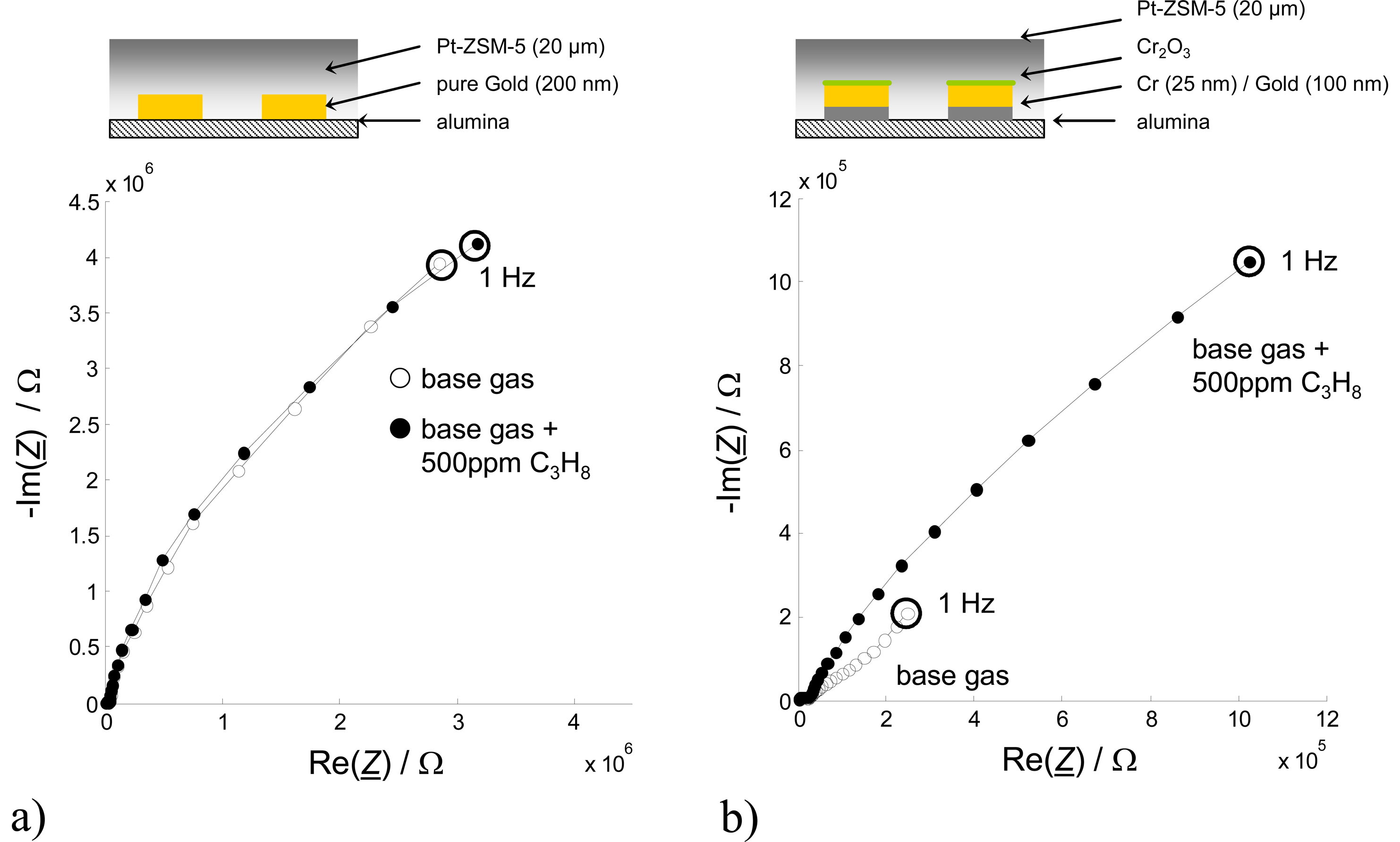
10]. The importance of the Cr
2O
3 layer, which will be denoted in the following as intermediate layer due to its allocation between gold electrodes and zeolite film, becomes obvious if one compares impedance spectroscopy data of sensors with and without Cr
2O
3 intermediate layer (
Fig. 1a, cf. also [
10] for details). Sensors without a Cr
2O
3 intermediate layer remain almost unaffected by hydrocarbon gases in the ambient atmosphere, which is in contrast to the strong sensor response, when hydrocarbons are present.
The microscopic reasons for this sensing behavior have not been fully elucidated yet. It is assumed in [
10] and [
11], that interfacial reactions at the boundary between Cr
2O
3 and the Na
+ - ion conducting zeolite are likely, since the effect appears in the low-frequency range of the two-wire impedance spectroscopy measurements. However, [
12] and [
13] ascribe the sensing effect to a decrease of the Na
+ ionic mobility in the zeolite, which is caused by hydrocarbon adsorption in the pores of the zeolite. Hence, one has to distinguish clearly, whether the sensing effect is a bulk phenomenon or an electrode interfacial process.
Usually, IS is carried out in a two-wire mode, i.e., both sample voltage and current are measured with the same electrodes. In four-wire techniques, current stimulation electrodes and measuring voltage electrodes are separated from each other. Due to the currentless voltage pick-off, electrode effects should not occur and the impedance result should only reflect “bulk” contributions (i.e. grain and grain boundary contributions) of the investigated material. Hence, it should be possible to distinguish between electrode and bulk effects by four wire IS on these Na+ ion conducting materials.
It is the aim of this study to investigate the above-mentioned novel hydrocarbon gas sensor effect by four-wire IS on a planar electrode setup. When comparing two- and four-wire results, electrode contributions of the measured two-wire spectra will be separated. It will be investigated, whether the gas dependent effect of this type of sensor occurs at the electrode or in the bulk. Additionally, an improved evaluation method is suggested.
2. Design of Electrode Structure and Sensor Setup
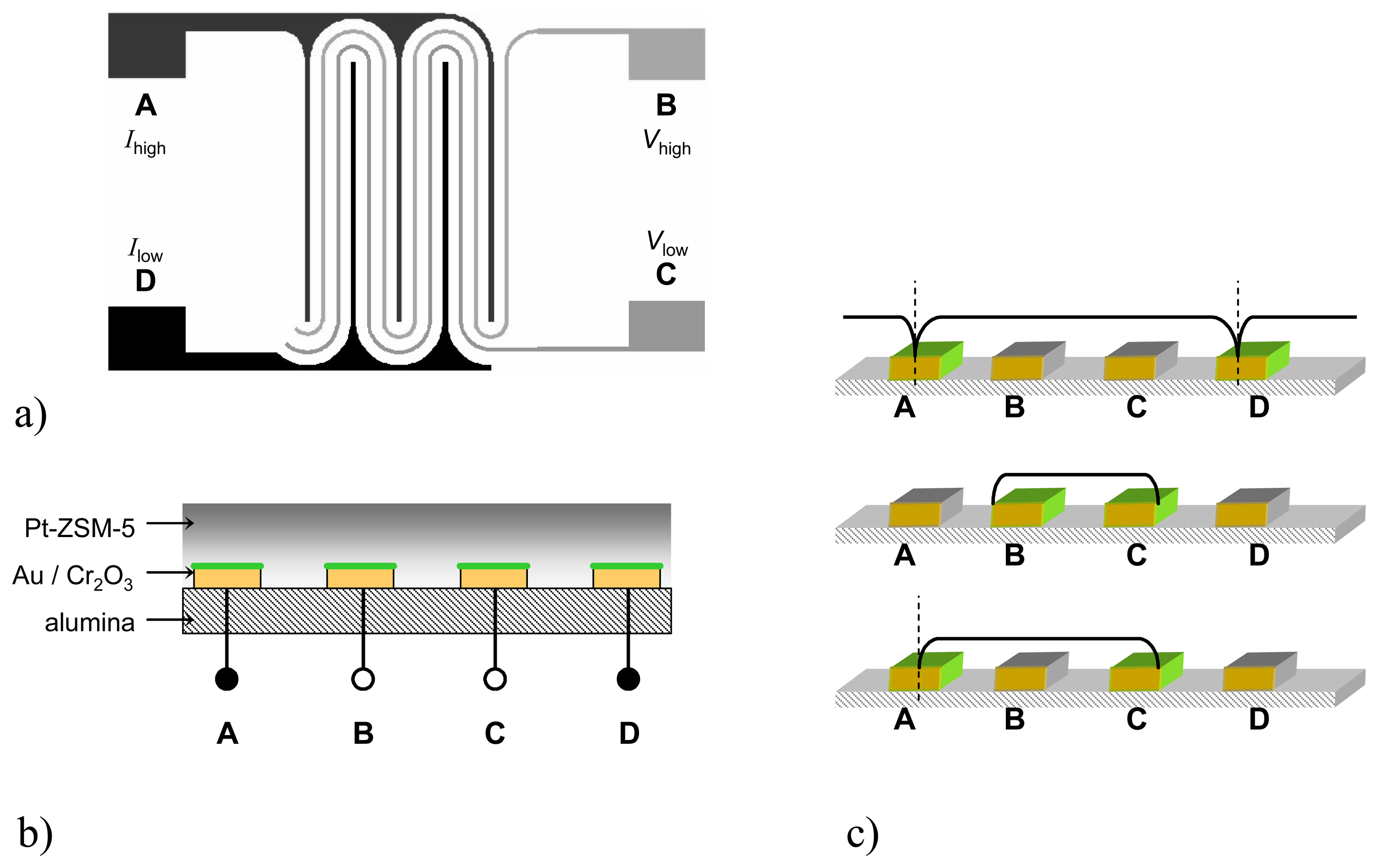
To obtain a two-dimensional planar setup with four separated electrodes, a configuration as shown in
Fig. 2a was chosen. Between the wider-spaced IDEs A and D, two meandered electrodes (B and C) are interposed. In one operation mode, the current is applied to the outer electrodes A (
Ihigh) and D (
Ilow) and the resulting potential is picked off at the inner electrodes B (
Vhigh) and C (
Vlow) as shown in
Fig. 2a. Recently, a similar setup was suggested for dc measurements to enhance selectivity and to discriminate two different gases [
14].
The structures (lines = spaces = 12 μm) were manufactured on alumina substrates (Ceramtec, Rubalit 710) using lift-off-technique. At first, the desired IDE pattern was manufactured by photolithography. Then, the Au electrode material (100 nm) was applied on a chromium thin-film with a thickness of 25 nm. The chromium serves as a bonding agent and - since chromium tends to diffuse rapidly through the gold film when heat-treated [
15] - as a chromium source for the desired chromium oxide film which is necessary for the sensing effect. The IDE area (4 x 4 mm) was covered by a Pt-doped ZSM-5 zeolite thick-film of about 20 μm thickness (
Fig. 2b). Preparation of the zeolite paste was carried out by ion exchange of a commercial Na-ZSM-5 powder (Südchemie) as reported in [
10].
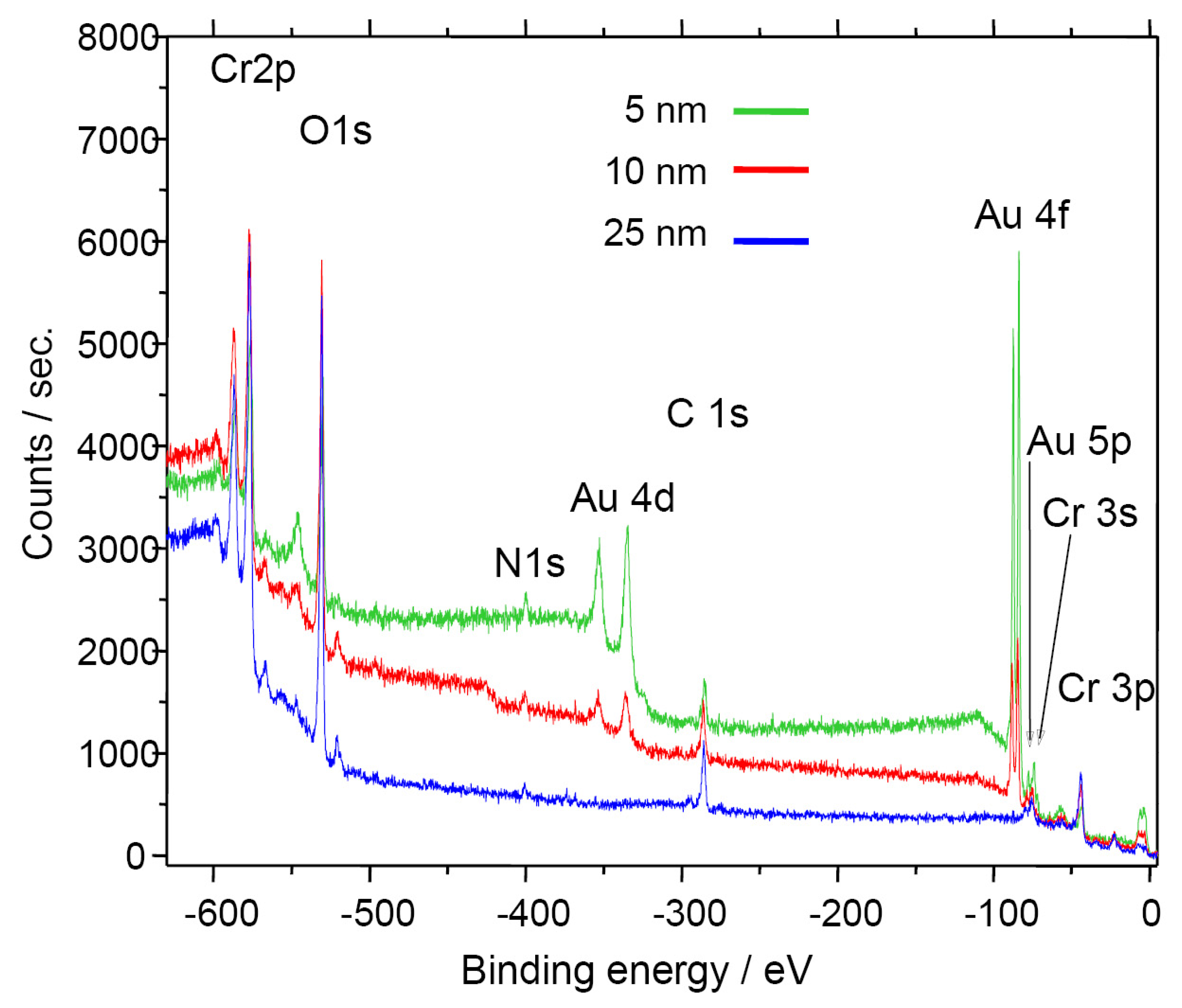
The in-situ formation of the Cr
2O
3 surface on the electrode was verified by XPS measurements. Different samples with varying chromium bonding layers (5, 10 and 25 nm) were covered by Au electrode films with equal thickness. All samples were heat-treated for 6 h at 450 °C (similar to the zeolite thick-film paste processing). The surface analysis (
Fig. 3) shows no Au peak in case of a relatively thick Cr bonding layer (25 nm). Hence, it is clearly demonstrated that with this manufacturing process, a closed Cr
2O
3 film forms, covering selectively and fully the electrodes.
Many four-wire dc investigations reported in the literature are carried out on material compacts. In contrast, a planar setup offers many advantages:
- -
in contrast to material compacts, the use of thick-film gas sensitive layers offers high gas diffusion rates to the electrodes and therefore relatively fast sensor kinetics.
- -
the sensor area can be easily heated to a constant working temperature, for example by use of a thick film heater on the backside of the substrate.
- -
screen-printing on planar substrates is an effective and inexpensive technology for applying the functional layer. It offers the possibilities for fast material tests or building up sensor arrays.
- -
the setup is close to the real sensor setup.
Certainly, this planar setup cannot provide ideal four-wire measurement conditions, such as infinitesimal electrodes for voltage pick-off. However, it will be shown in this paper, that at least in our case, sensor characterization results fit well with the theoretical considerations.
The sensor tests were conducted in a wet base gas with 2.5 % H
2O and 10 % O
2 in N
2 at 300 °C. For hydrocarbon (HC) detection tests, 500 ppm propane were added to the carrier gas. All impedance spectroscopy data (Novocontrol Alpha-Analyzer with ZG4 interface) were obtained in the frequency range of 10 MHz to 1 Hz (amplitude of the applied ac voltage:
Vrms = 40 mV). Due to the very high internal resistance of the impedance analyzer (1 TΩ), an undesired effect resulting from ohmic leakage currents through the analyzer can be excluded. As the input capacitance is in the range of a few pF, at frequencies below several ten kHz capacitive leakage currents can be neglected as well. Possible errors might occur for frequencies above 100 kHz, yielding in irregularities around
Z = 0 in
Fig. 5b. For the interpretation of the data with respect to distinguishing between electrode and bulk effects, the high frequency data are not relevant and need not to be considered.
3. Fundamental Considerations
Typically, two-wire impedance results of zeolite covered IDE with blocking electrodes consist at least of a “bulk” semicircle and an electrode “tail” [
16]. The presented planar four-wire electrode setup also provides the possibility to conduct
two-wire impedance spectroscopy. From
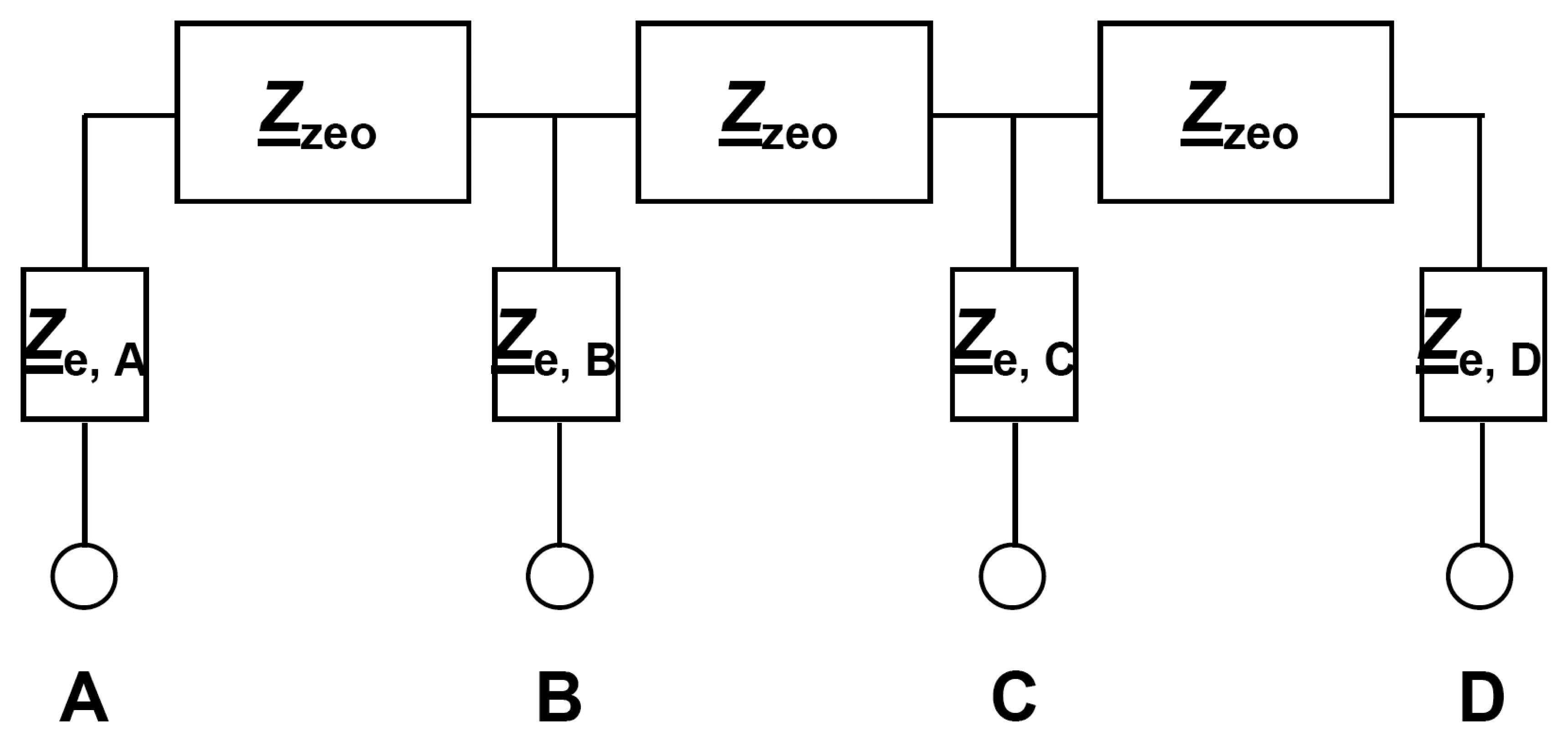
Fig. 2b and Fig. 2c, a simplified electrical circuit model as shown in
Fig. 4 can be deduced and the following results should be expected.
If one considers schematically the distribution of the electrical field (
Fig. 2c), it becomes obvious that there is a symmetry line with zero
x-component in the middle of electrodes A and D. Therefore, only one half of the electrode area is available for one IDE element if electrodes A and D are used for measurements. Assuming that the half electrode area causes a double electrode resistance, one has to conclude
Connection at the inner electrodes (B and C) causes a field distribution that uses the entire electrode surface, because these electrodes have no zero field in their middle.
Pairwise two-wire connection of the outer electrodes (between A – D) should lead to the highest bulk impedance, since the size of the high-frequency semicircle should include three parts of the zeolite bulk impedance
Zzeo. The low-frequency contributions should include the interfacial and electrode impedances
Ze,A and
Ze,D (in sum, denoted as 4 ×
Ze). Hence, the overall electrical impedance
Z2-wire between A and D is calculated after (
Eq. 3).
Likewise, two-wire connections of the inner electrodes (B – C) include 2 ×
Ze, but only 1 ×
Zzeo. Therefore, the high-frequency semicircle size representing the bulk impedance should be only one third of the above-mentioned result from
Eq. (3). The low-frequency electrode part is expected to be 2 ×
Ze (
Eq. 4).
Furthermore, side-by-side connections (A – B and C – D) should lead to the same electrode values but to different bulk contributions compared with crosswise connections (A – C and B – D,
Eq. 5 and
Eq. 6).
Thus, the bulk contributions are expected to depend on the distance of the two-wire contacts, and the electrode contributions are expected to vary between 2 × Ze and 4 × Ze.
Measured in the four-wire mode, in accordance to
Fig. 4, the measured impedance
Z4-wire is 1 ×
Zzeo. Electrode impedances should not contribute to
Z4-wire, since ideally the voltage is picked off currentless (see above) and
Ze at the inner electrodes B and C do not play a role.
Utilizing
Eq. 4 and
7, the electrode contribution (
Ze) can be calculated as the difference between the two-wire measurement at the inner electrodes and the four-wire measurement (
Eq. 8):
4. Electrical Results and Discussion
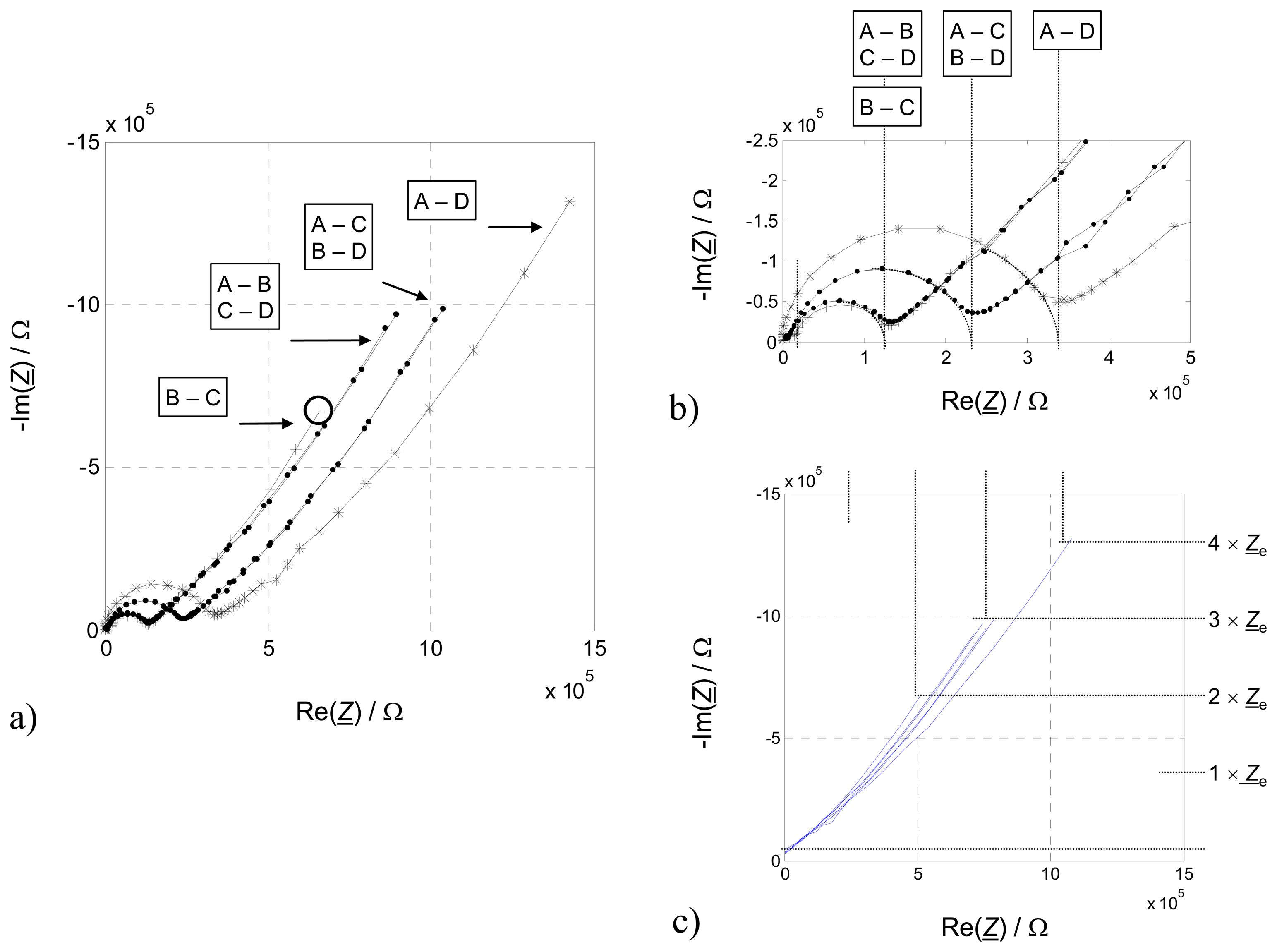
In a first step, the functionality of the transducer was verified by comparing two-wire IS results in all possible connection modes (
Fig. 5a). Semicircles representing an R-C parallel equivalent circuit were fitted to the measured high-frequency values and its intersections with the real part axis in the Nyquist-Plot were considered. As expected from section 3, these values are equidistantly distributed due to the different distances between the contacting electrodes (
Fig. 5b). Since each section between two electrodes increases the bulk impedance of the zeolite by 1 ×
Zzeo, the results seem plausible.
If one has a close look on the low-frequency contributions of the two-wire results, evidently not all “tails” show the same length. In the basic considerations above, it was deduced that the electrode contribution of the combination A – D is 4 ×
Ze, whereas for side-by-side connections (A – B, C – D) and crosswise connections (A – C, B – D) the electrode contribution should be 3 ×
Ze, and 2 ×
Ze for B – C configuration. If one subtracts the volume parts (
Zzeo) of the high frequency semicircle (
Fig. 5c), which are ascribed as a bulk contribution, it can be easily seen that the relation 4:3:2 as expected holds. These findings do strongly support that an electrode effect is responsible for the low frequency tail.
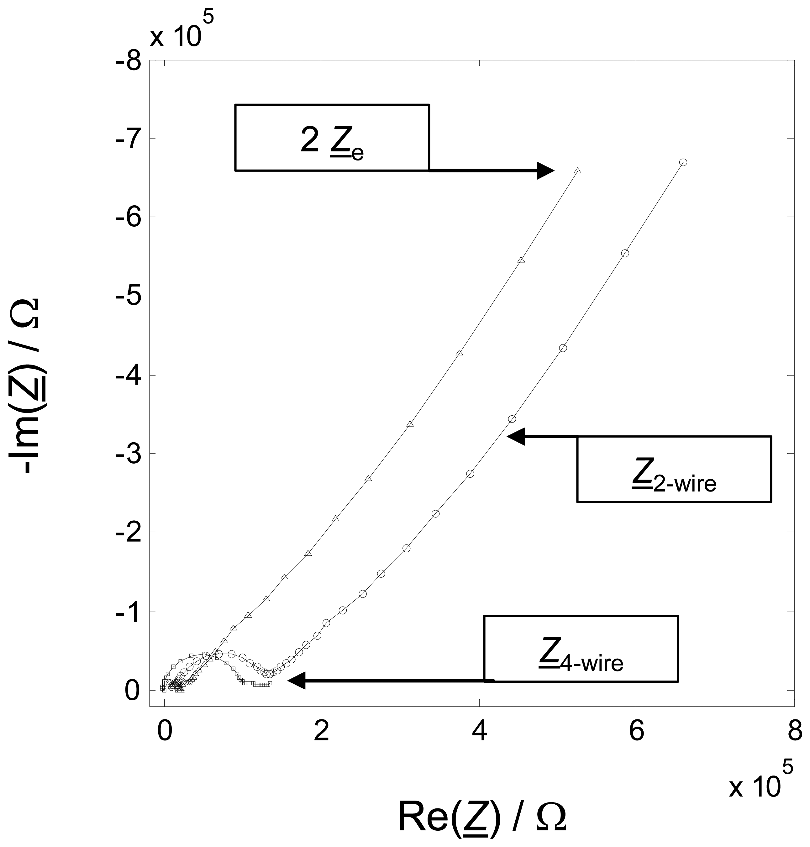
In a second step, four-wire impedance data were taken. The results are plotted together with the two wire data (B – C) in
Fig. 6. First of all, the missing electrode impedance attracts attention. As expected from
Eq. 7, the “pure” zeolite bulk impedance is measured currentless with almost no electrode contribution. The size of the measured bulk semicircle is almost equal to the high-frequency part of side-by-side two-wire results.
Application of
Eq. 8 separates electrode from bulk contributions.
Figure 6 shows both, the two-wire (B – C) and the four-wire measurement in one diagram. The third graph in
Fig. 6 is the resulting electrode impedance 2 ×
Ze, when
Z4-wire is subtracted from
Z2-wire. This graph consists only of an electrode “tail”. The bulk semicircle does not appear anymore.
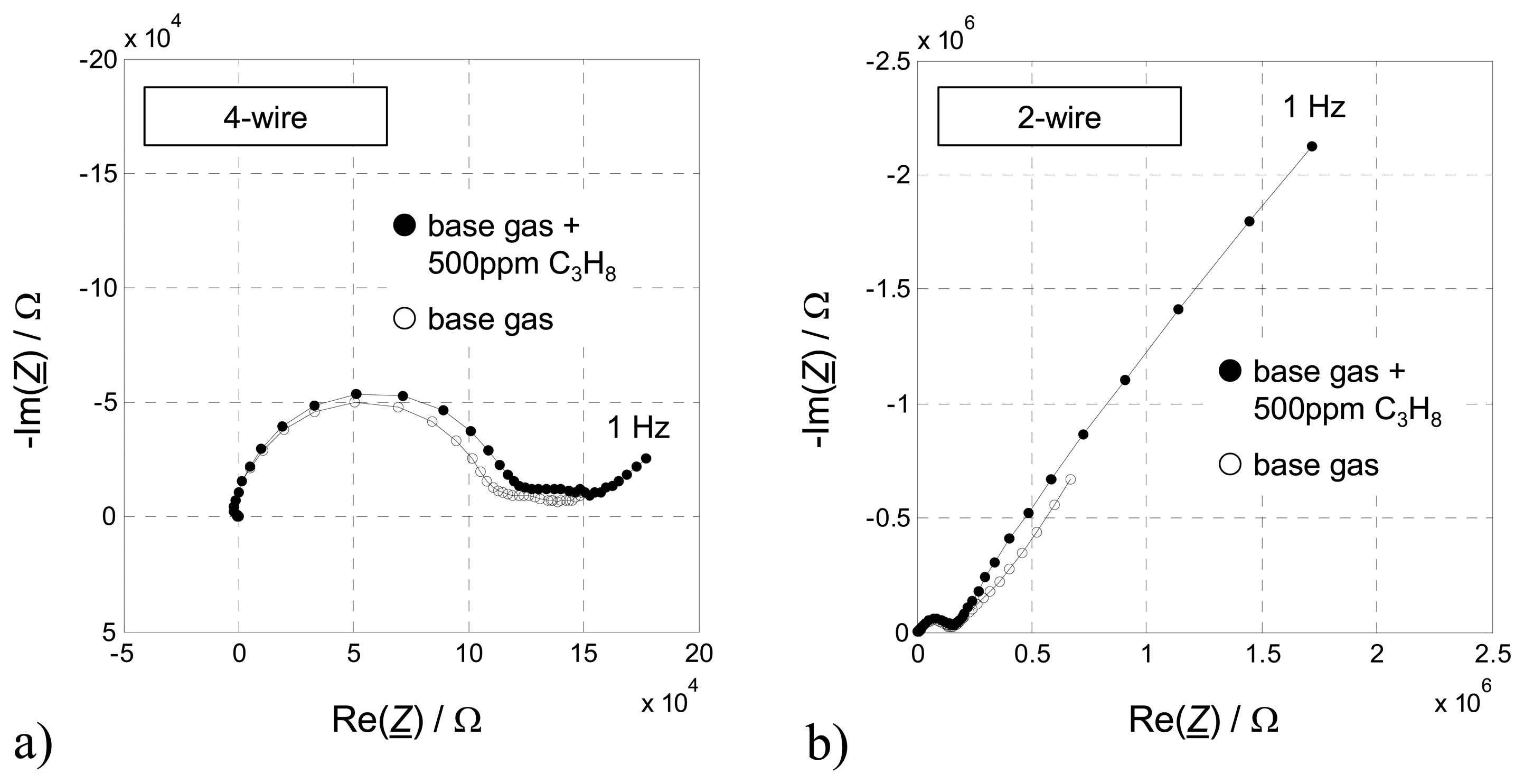
In a third step, 500 ppm propane was added to the base gas. This experiment helps to decide, which part of the sensor is responsible for the HC sensitivity.
Figure 7 shows the results. Whereas the four-wire spectra do not show a significant sensitivity towards HC (only a very slight increase can be seen in
Fig. 7a), the impedance in the lower frequency range of the two-wire measurement increases strongly (
Fig. 7b).
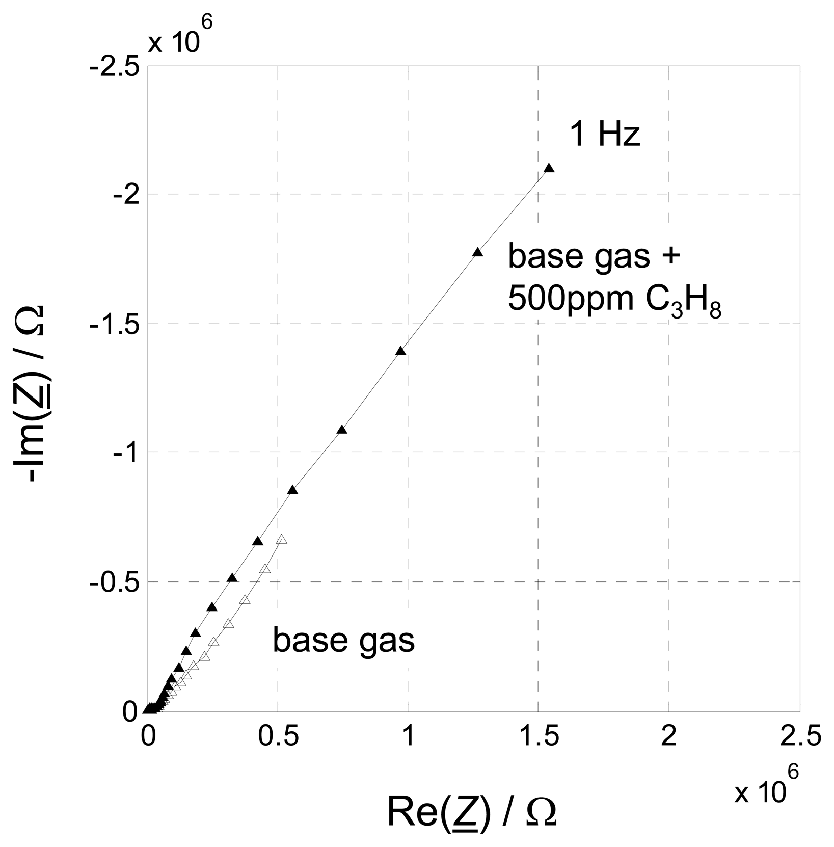
For both atmospheres (with and without 500 ppm propane), the separated electrode impedances were calculated by applying
Eq. 8. Consequently, only the “pure” low-frequency electrode contributions appear in the complex plane diagram, showing the strongly dependence on HC. These results are presented in
Fig. 8. Without any doubts, mechanisms at the electrode are responsible for the measuring effect. Volume effects can be neglected. The presented method utilizing interposed four-wire IS verifies this clearly. Hence, future work will has to have a closer look at the processes that happen at the electrode when hydrocarbons are present in the sensor ambient.
The exact reasons for this gas sensor effect are in discussion. Two preliminary models are supposed in the literature:
- 1)
When a zeolite compact pellet is contacted by Cr
2O
3 on Au on one side and a reference electrode on the other side, an electromotive force can be measured. Changes due to HC concentration variations in a carrier gas flow might appear because adsorption of hydrocarbons inside the zeolite pores lead to changes of the Na
+ activity. By assuming an interfacial Na-Cr-O phase between zeolite and Cr
2O
3 electrode, their formation at the electrode depends on the Na
+ activity and therewith on the HC concentration. The potential changes might have also influence on the electrode impedances [
17].
- 2)
It is known from literature that the hole concentration of p-type conducting chromium oxide is hydrocarbon concentration dependent [
18]. Since it is also known that a closed chromium oxide film between Au electrode and zeolite exists, a Schottky type barrier is likely. Now, one can model the Na
+ mobility, which depends on the displacement from the equilibrium position. Initial calculations confirm that under these assumptions a changing hydrocarbon concentration does strongly affect the impedance spectra, mainly at low frequencies. A good correlation between measured and calculated data is found [
19], [
20].
It should be annotated here, that this planar setup with interposed interdigital electrodes can be also applied to other ion conducting sensors with blocking electrodes. It can either replace the application of additional ion conducting electrodes as for instance suggested in [
21] where sodium carbonate electrodes are used to circumvent electrode effects. Such ion conducting electrodes are prone for ageing and poisoning, whereas the above described four-wire setup does need neither additional materials nor additional processes. By a simple electronic subtraction of the two-wire and the four-wire impedance, the electrode effect can be separated and the interfering volume impedance can be suppressed. This is highly preferable in a sensor electronic, since one would prefer measuring at only one frequency instead of acquiring an entire spectrum and subtracting the gas-insensitive high frequency part that represents the bulk.
