1. Introduction
Flexible ureteroscopy (FURS) is a minimally invasive technique for diagnosing and treating upper urinary tract diseases such as kidney stones and urothelial carcinoma by passing through the natural urinary tract, bladder, and ureter [
1,
2]. Compared to traditional open surgery, FURS offers less pain and faster recovery. However, the complexity of the surgery is increased as urologists need to stand for long periods while holding the flexible ureteroscope for intricate procedures, and the frequent use of X-ray imaging during the operation exposes them to radiation risks [
3]. Robotic-assisted FURS systems have emerged to address these challenges [
4,
5]. Robotic systems not only enable the remote operation of the ureteroscope, reducing radiation exposure, but also improve surgical precision through stable operation [
6]. However, traditional robotic-assisted FURS systems in operation lack force feedback at the ureteroscope tip, which makes it difficult for surgeons to perceive tactile information in real-time, such as determining whether the tip is touching stones or normal tissues. This lack of force feedback can lead to instrument damage or surgical complications [
7,
8]. Therefore, developing a force sensor that can be integrated at the ureteroscope tip is essential.
Force sensors provide real-time force feedback [
9]. Currently, there is still a lack of force feedback at the tip of the ureteroscope, which hinders the surgeon’s ability to precisely control the instrument and increases the risk of unintended tissue damage, making the procedure less safe and effective. Existing force sensors can be broadly categorized into electrical-based and optical-based force sensors. Electrical-based sensors, while generally cost-effective and easy to manufacture, suffer from issues like large size and susceptibility to electromagnetic interference. In contrast, optical-based sensors are immune to electromagnetic interference and can be miniaturized, but they are often more complex and costly to implement. Electrical-based force sensors, such as piezoresistive and piezoelectric types, are limited by their large size, which makes them incompatible with ureteroscopes. Additionally, they are unable to resist electromagnetic interference, significantly restricting their application [
10]. Optical-based force sensors are mainly classified into intensity-modulated, phase-modulated, and wavelength-modulated types. Intensity-modulated fiber-optic force sensors rely on the measurement of voltage or current induced by force-induced intensity changes [
11]. However, each fiber-optic sensor requires two independent optical fibers to reflect the interaction forces, which negatively impacts miniaturization and makes integration at the ureteroscope tip challenging. Phase modulation employs Fabry–Perot interferometry for measurements [
12,
13], which involves using multiple reflections between two parallel reflective surfaces to create interference patterns that can be used to determine changes in distance or force. However, the maximum measurement range is limited to half the wavelength of the light, which cannot meet the high precision force measurement requirements at the ureteroscope tip. Wavelength modulation, using fiber with inscribed fiber Bragg gratings (FBGs) as sensing elements, can overcome the limitations of optical intensity fluctuation and phase discontinuity [
14]. Additionally, FBG-based wavelength modulation provides high sensitivity, stability, and ease of integration, making it a superior choice for precise force measurements at the ureteroscope tip. Recently, Zhao et al. [
15] presented embedded FBG sensors fabricated by ultrasonic additive manufacturing, demonstrating robust high-frequency dynamic strain measurements in metal structures. In comparison, our sensor features significant miniaturization, tailored structural optimization, and comprehensive calibration methods, specifically designed for delicate force measurements in ureteroscopic surgical applications.
FBG technology, due to its high sensitivity, compact size, and excellent biocompatibility, has emerged as an ideal solution for sensing tactile information at the tip of ureteroscopes [
16]. FBG-based force sensors can be integrated into the tip of flexible ureteroscopes to detect forces applied at the tip by measuring variations in the Bragg wavelength. By providing real-time force feedback, these sensors significantly enhance the safety of surgical procedures and the operational precision of the surgeon [
17]. Gan et al. [
18] developed a uniaxial FBG force sensor for palpation in minimally invasive surgeries, incorporating an elastomer with a helical structure to improve force sensitivity. However, this helical structure is susceptible to interference from lateral forces, limiting its practical utility. Gao et al. [
19] integrated an FBG force sensor into the forceps used in retinal microsurgery, but the sensor’s low accuracy makes it unsuitable for detecting subtle contact forces in FURS applications. He et al. [
20] developed an FBG tactile sensor for vitreoretinal surgery and discussed the influence of different structures on force sensing. However, this sensor has a limited force detection range, while FURS generally requires a force detection range of up to 1 N. In our previous work [
21], a dual-elastomer FBG tactile sensor was developed for temperature decoupling. However, the 3 mm diameter of the sensor limits its integration into the ureteroscope tip.
To address these limitations, this paper proposes a miniature FBG tactile sensor with resistance to lateral forces and temperature monitoring capabilities. The sensor is integrated into the tip of a flexible ureteroscope to measure contact forces applied to the ureteral wall or kidney stones.
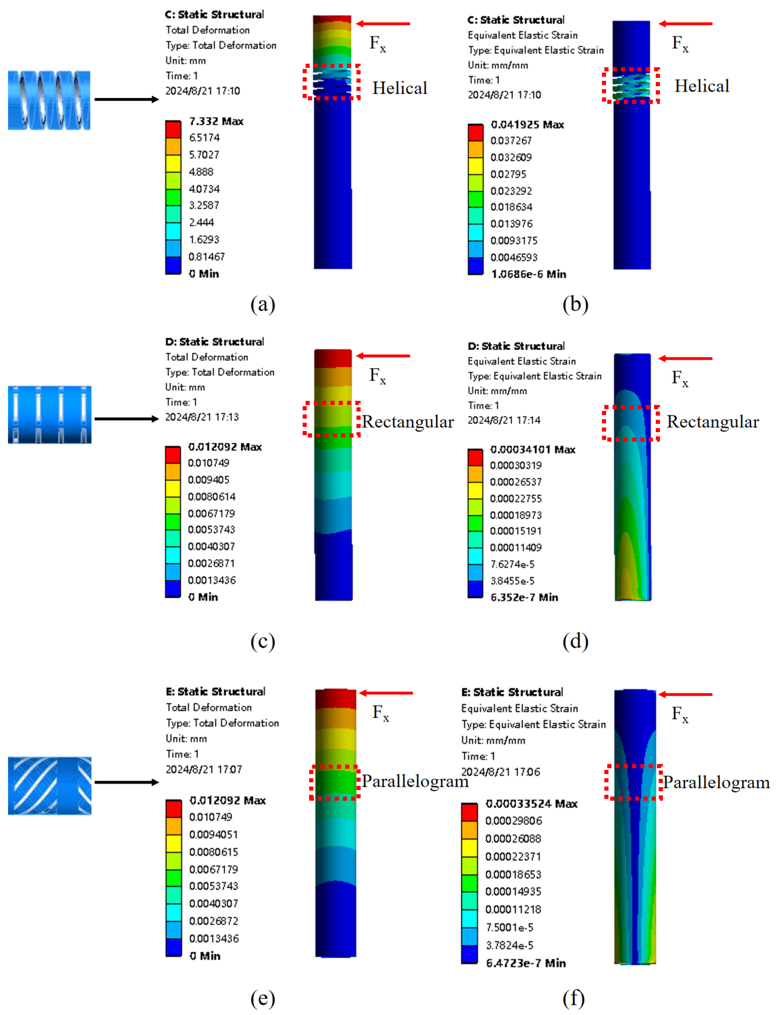
Section 2 details the sensor’s structural design and sensing principle and analyzes finite element analysis comparing various structures to demonstrate the sensor’s resistance to lateral interference.
Section 3 presents the fabrication and calibration of the sensor prototype and includes integration of the sensor into the ureteroscope tip for performance testing in a simulated lithotripsy procedure, detailing the testing environment, equipment used, and specific metrics evaluated.
3. Sensor Experiments
3.1. Sensor Parts
During the fabrication process of the designed FBG tactile sensor, the initial step involved customizing the optical fiber inscribed with FBG. To ensure the alignment of the FBG region with the flexure section of the elastomer, a black marker was applied near the FBG during the design stage to facilitate fiber bonding. The FBG was fabricated using femtosecond laser inscription, a technique that provides precise control over grating parameters while minimizing thermal damage. The grating exhibits a physical length of 2 mm, a central wavelength of 1550 nm, and a reflectivity greater than 90%. These parameters were deliberately selected to meet the rigorous integration requirements of a flexible ureteroscope.
Specifically, the 2 mm grating length allows the sensing element to be seamlessly incorporated within the 1.5 mm working channel, ensuring that the overall sensor remains compact and does not impede maneuverability. The choice of a 1550 nm wavelength is advantageous due to its compatibility with standard optical interrogation systems and its low transmission loss in optical fibers, which is vital for accurate sensing in a clinical environment. Furthermore, the high reflectivity ensures a robust signal-to-noise ratio, enabling the precise detection of minor wavelength shifts induced by axial forces and temperature fluctuations. Regarding manufacturing, given that the designed FBG tactile sensor is intended for FURS applications with a diameter of only 1.5 mm, stringent requirements are imposed due to the small scale. The sensor is constructed from medical-grade 304 stainless steel, with components fabricated using a Swiss-type lathe in a single-step machining process to ensure high precision. Furthermore, for the elastomer component, since the hollow cylindrical body has a wall thickness of only 0.3 mm, laser cutting technology was employed to create a sensitivity-enhancing structure.
3.2. Sensitivity Coefficients Calibration
The designed FBG tactile sensor was calibrated for force sensitivity and temperature sensitivity coefficients. First, a fixture was designed to secure the sensor, which depicted the model and the actual image of the fixture, respectively. The fixture consisted of an upper and a lower part, with a 1.5 mm through-hole for placing the designed FBG tactile sensor, which was then secured using screws.
The calibration system mainly consisted of the designed sensor, an ATI 6-axis force-torque sensor (Nano17 SI-12-0.12, Apex, NC, USA), a NetBox (9105-NETBA, ATI, Apex, NC, USA) used for data transfer, an FBG interrogator (SA-10002454; sampling rate: 100 Hz; resolution: 1 pm, Shenzhen, China), a automatic displacement stage, a manual dispalcement stage, a fixture, and a computer. During the calibration process, since movement in the automated translation stage was required, the force value monitored by the ATI sensor and the central wavelength shift displayed by the FBG interrogator were recorded simultaneously. Therefore, a LabVIEW program was developed. Movement in the x-direction of the automated translation stage corresponded to the z-direction of the FBG sensor. Thus, the control page for the x-direction of the automated translation stage was configured within the software interface. The real-time force feedback from the ATI sensor and the central wavelength value of the FBG interrogator were also displayed on the main interface of the software. By pressing and holding the save button, the force values from the ATI sensor and the wavelength shifts from the FBG interrogator could be saved simultaneously, facilitating the force calibration experiment.
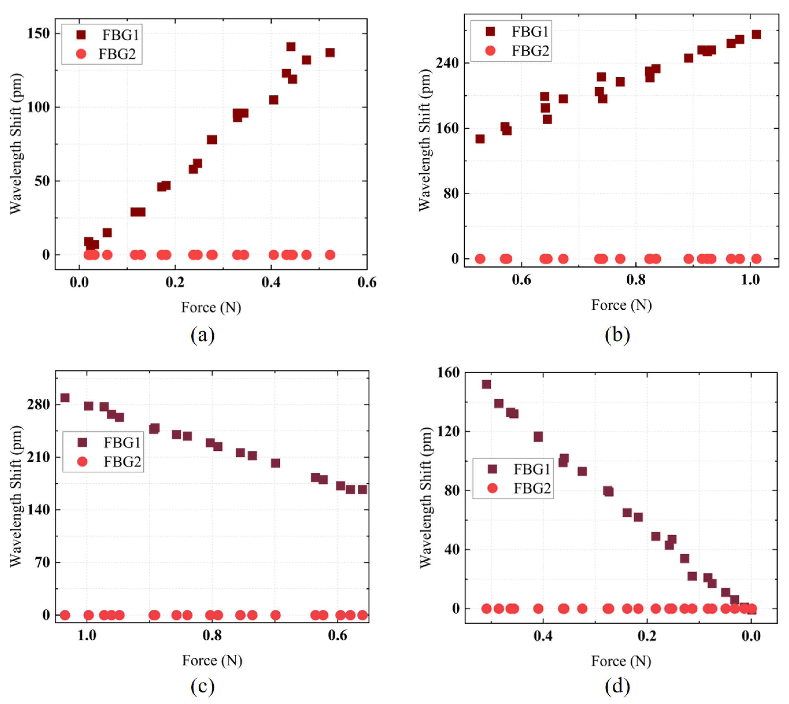
The automated translation stage was moved to allow the ATI sensor to make contact with the FBG sensor for calibration. Data recording was performed using the designed calibration software. Four experiments were conducted for the intervals [0–0.5 N], [0.5–1 N], [1–0.5 N], and [0.5–0 N] to record the sensitivity of the designed FBG tactile sensor in these ranges. The experimental results are shown in
Figure 5a–d. In the [0–0.5 N] range, the FBG tactile sensor exhibited a sensitivity of 283.85 pm/N with a linearity of 98.27%; in the [0.5–1 N] range, the sensitivity was 258.57 pm/N with a linearity of 96.34%; in the [1–0.5 N] range, the sensitivity was 260.75 pm/N with a linearity of 99.68%; and in the [0.5–0 N] range, the sensitivity was 296.44 pm/N with a linearity of 99.67%. Because of the 0.5 N pre-tension in the optical fiber, the elastomeric structure initially deformed more readily at lower loads, yielding higher sensitivity; as the load surpassed 0.5 N, the elastomer reached a stiffer regime with slightly reduced sensitivity. Nevertheless, each sub-range remained linear due to the consistent mechanical properties of the elastomer and uniform fiber bonding. This slight discrepancy arose from minor mechanical hysteresis in the elastomeric structure and adhesive bond, where progressive elastic deformation upon loading and a brief relaxation delay upon unloading led to small differences. The calibration results demonstrate that the designed force sensor has high force sensitivity and linearity, ensuring high accuracy in force detection, which is advantageous for contact force measurement in FURS.
3.3. Investigation of Dynamic Performance
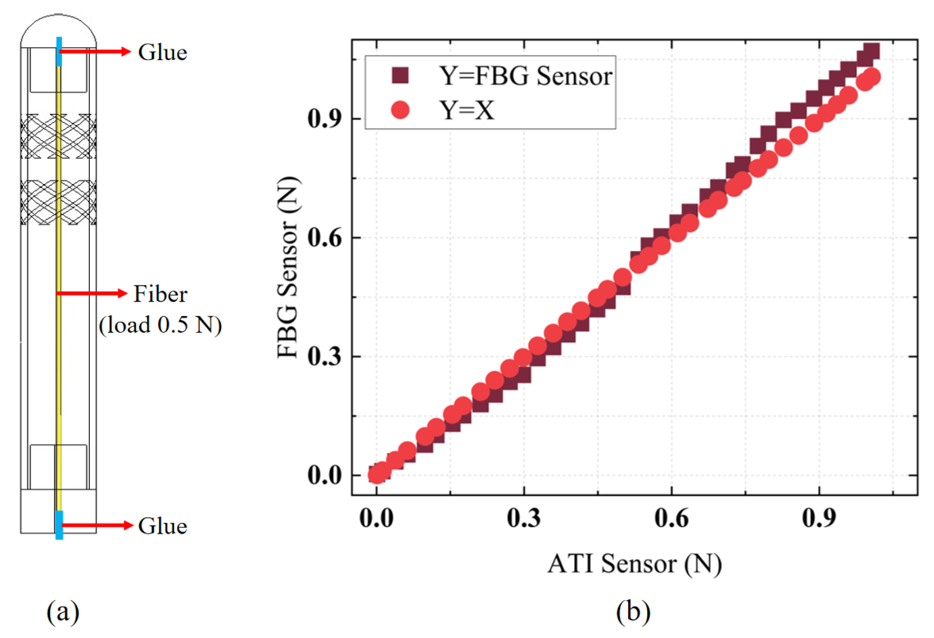
The designed FBG tactile sensor was calibrated using a segmented calibration method within small force ranges to facilitate accurate contact force measurements in practical applications. The higher sensitivity in the [0–0.5 N] range compared to the [0.5–1 N] range was attributed to the pre-tension of 0.5 N applied to the fiber before bonding the FBG tactile sensor, as shown in
Figure 6a, to maintain high force sensitivity and linearity. Thus, the sensitivity in the [0–0.5 N] range was greater than that in the [0.5–1 N] range. Additionally, the segmented calibration method improved force detection accuracy in practical scenarios. A dynamic force load was applied to the FBG tactile sensor to validate the accuracy of its force measurements.
Figure 6b presents a comparison between the force measurements obtained from the FBG tactile sensor and the ATI force sensor. It is evident that, within the dynamic force range of [0–1 N], the error obtained through segmented calibration did not exceed 0.07 N, and the sensor exhibited a high linear response, allowing for accurate contact force measurements.
3.4. Investigation of Dynamic Performance
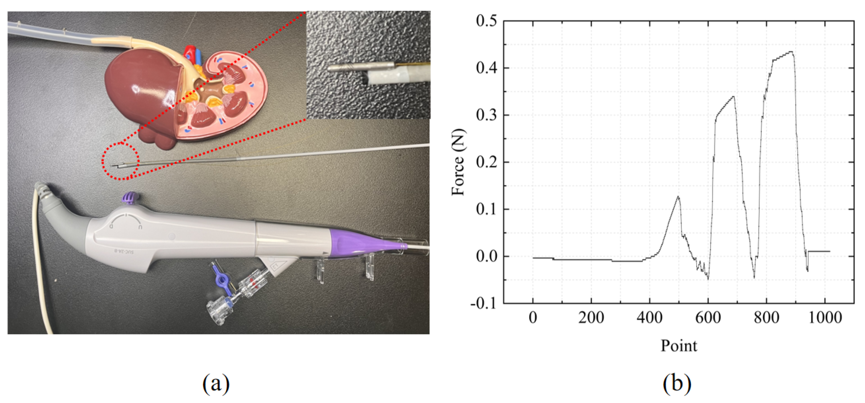
In FURS, the surgeon first inserts the flexible ureteroscope into the patient’s urethra, then advances it into the bladder. Subsequently, it is navigated from the bladder into the ureter. Due to the narrowness of the ureter, the surgeon must carefully manipulate the ureteroscope to avoid damaging the surrounding tissue. Finally, the ureteroscope is advanced into the renal pelvis and calyx regions of the kidney. In lithotripsy, stones are typically located in the ureter and kidney. Without force-sensing capabilities at the ureteroscope tip, excessive contact force during ureter insertion may damage the tissue, and distinguishing between stones and normal tissue is also challenging. The designed FBG tactile sensor was integrated into the tip of the flexible ureteroscope, and a kidney model was used to simulate the insertion process of the ureteroscope during lithotripsy, as shown in
Figure 7a. The ureter was fabricated using 3D printing, with some protrusions designed on the inner wall to simulate the presence of stones. The force measurement results are shown in
Figure 7b. The first peak represents the force response when contacting the ureter wall, while the subsequent two peaks represent the force response when touching the stones. It can be observed that the contact force was larger when touching the stones, whereas it was smaller in other regions. This verifies that the designed FBG tactile sensor in FURS not only has the capability to differentiate between stones and normal tissue but also protects the ureter wall from damage caused by medical instruments.
4. Conclusions
This work developed an FBG micro-force sensor that can be integrated into the tip of a flexible ureteroscope, with the objective of detecting and distinguishing stones from tissues during FURS lithotripsy procedures. First, the designed sensor has a total diameter of only 1.5 mm, exceeding the size constraints of current force sensors. Second, a flexure structure was designed to resist transverse forces, to enhance axial force sensitivity and mitigate lateral force load interference during force measurements. Comparative modeling and simulation analyses were conducted with several existing sensitivity-enhancing structures, demonstrating the superior performance of the proposed structure. Finally, an experimental calibration platform was established to determine the accuracy and sensitivity of the designed force sensor. Additionally, a simulated lithotripsy experiment was conducted. The sensor was integrated into the ureteroscope tip to conduct object detection experiments. Experimental results showed that the sensor could distinguish between various objects at the ureteroscope tip. The study of the flexible ureteroscope tip based on the FBG force sensor shows significant potential for improving the safety and efficacy of surgical interventions. By integrating advanced fiber-optic sensing technology, robotics, and artificial intelligence, real-time force feedback during surgery enhances the surgeon’s tactile perception and minimizes surgical risks. Future research will further advance the development of multimodal sensing technology, machine learning, and miniaturization, fostering innovation and breakthroughs in the application of FURS.

 ,
, 