
Research on the Design of an On-Line Lubrication System for Wire Ropes

Abstract
1. Introduction
2. Composition and Physicochemical Properties of Specialty Grease
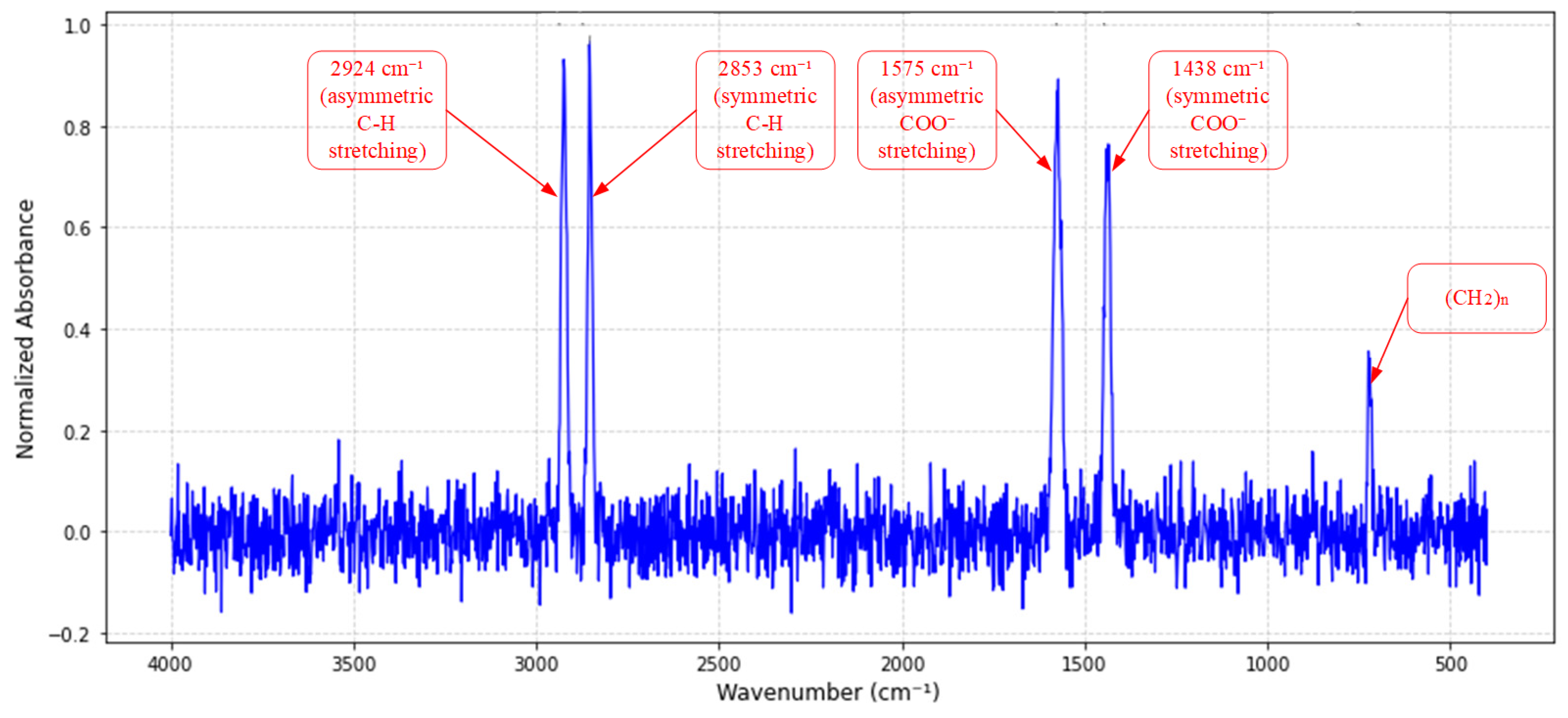
2.1. Spectral Characterization of Specialty Grease
2.2. Performance Analysis of Specialty Grease
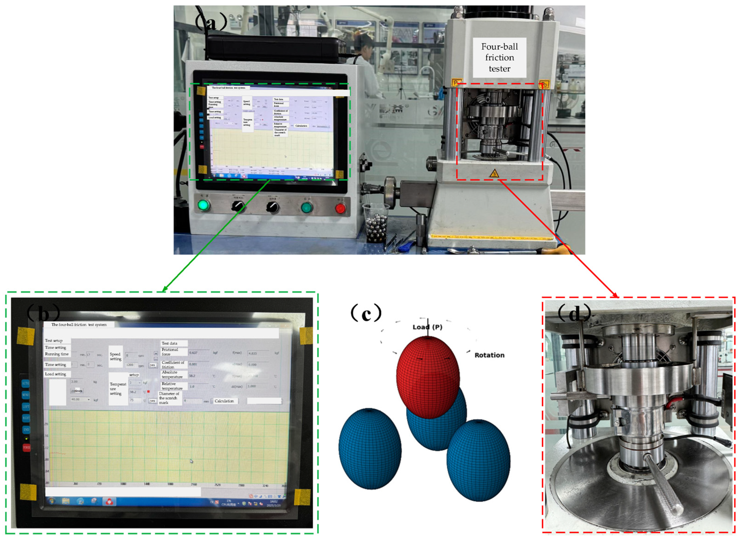
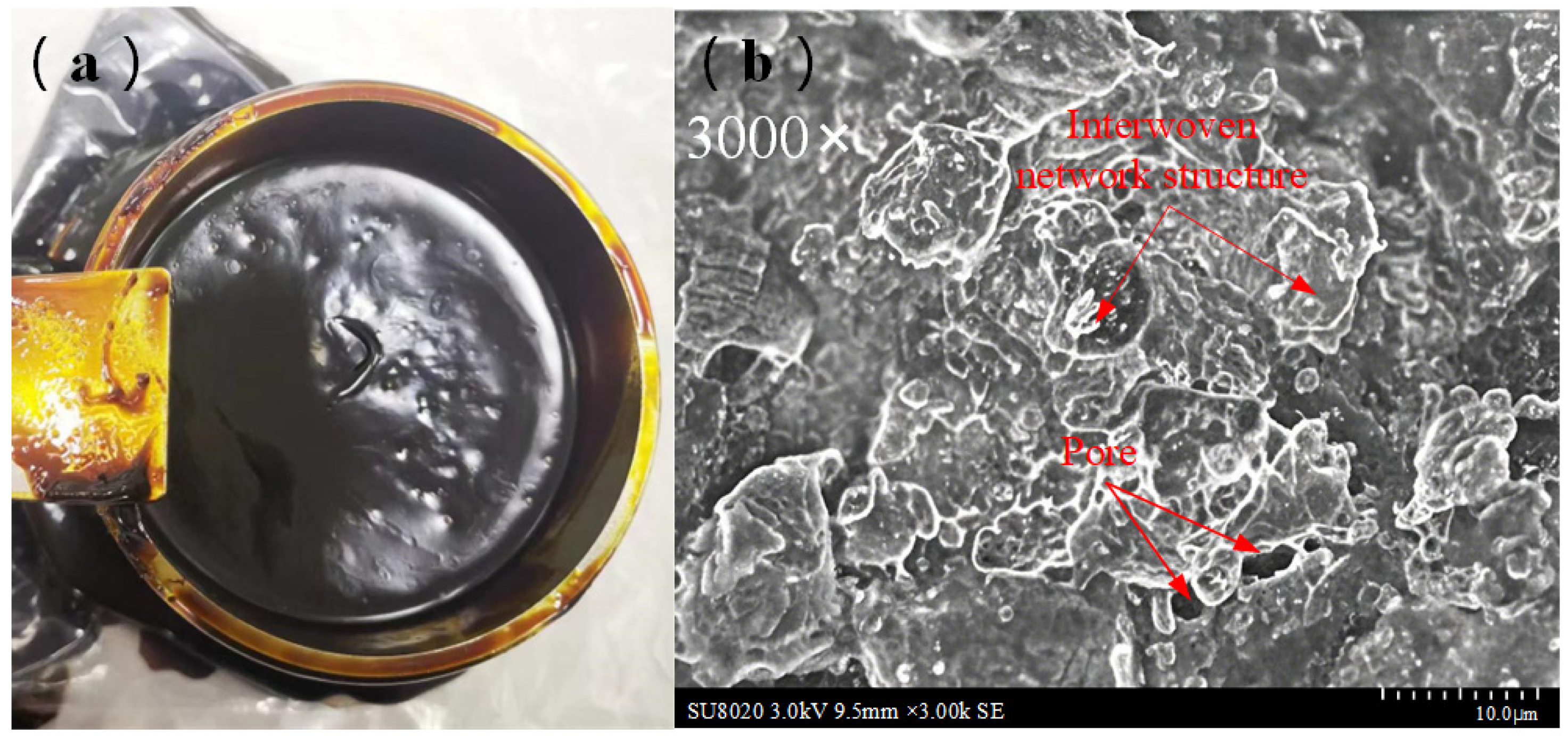
2.2.1. Four-Ball Friction Tests

| Test Parameters | Load (N) | Spindle Speed (r/min) | Time (s) | Temperature (°C) |
|---|---|---|---|---|
| Extreme pressure test | / | 1450 | 10 | 50 |
| Friction and wear test | 392 | 600 | 3600 | 75 |
| 392 | 1200 | 3600 | 75 | |
| 392 | 1800 | 3600 | 75 |
2.2.2. Comprehensive Performance Evaluation of Specialty Grease
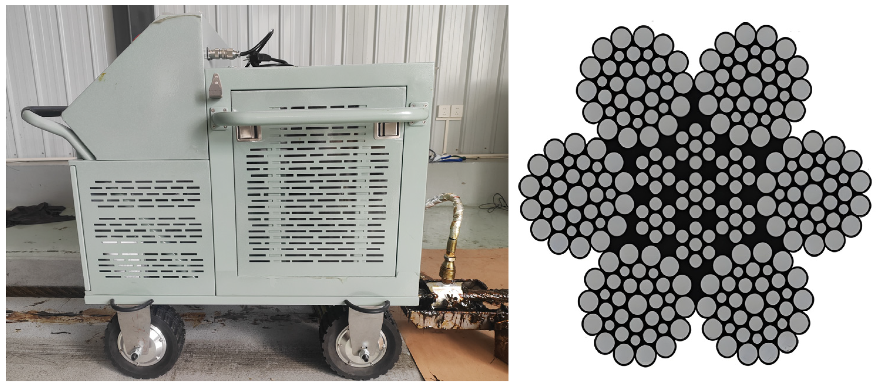
3. Design of Wire Rope Intelligent Lubrication System
3.1. Process Control Unit
3.2. Hydraulic Drive Unit
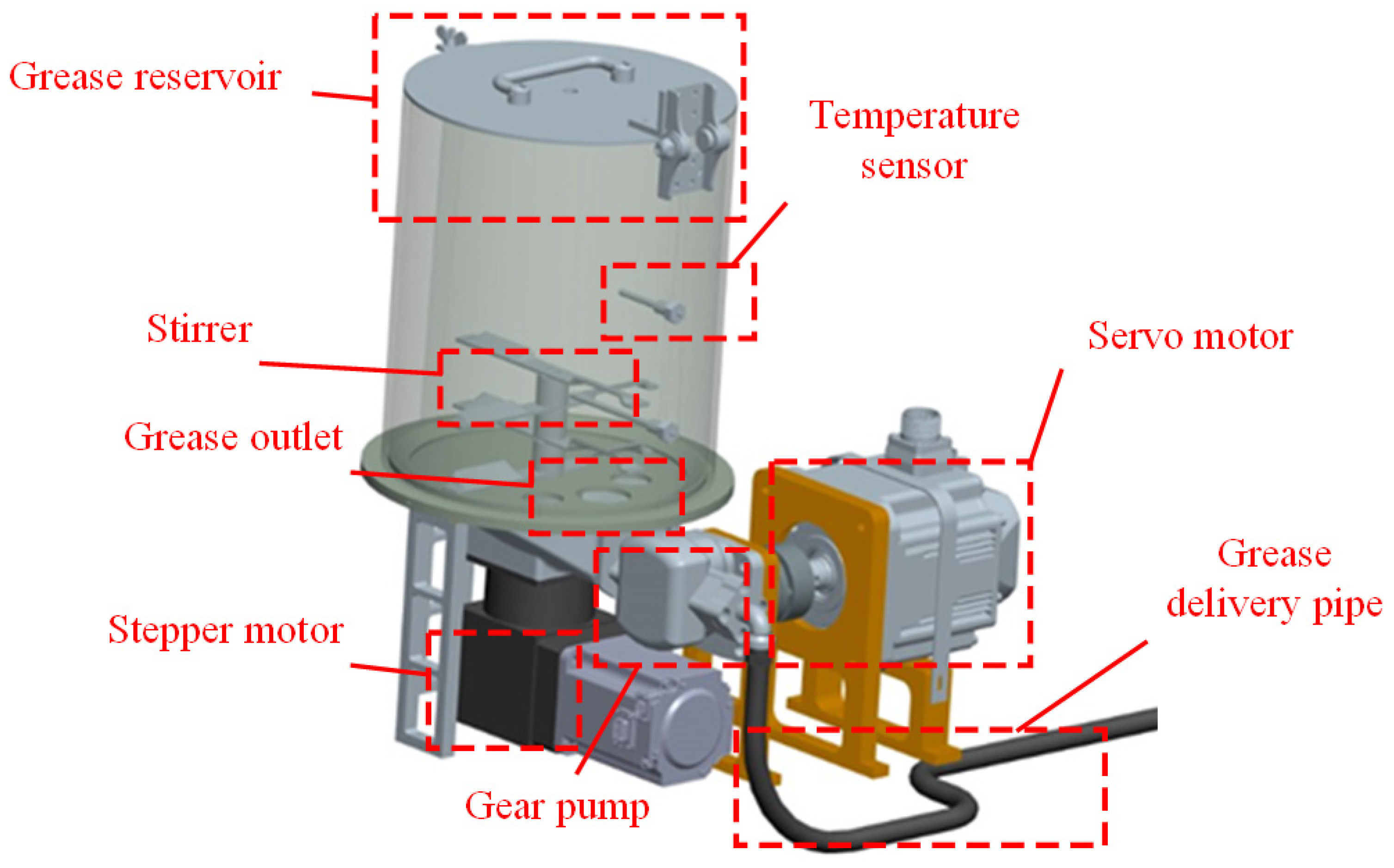
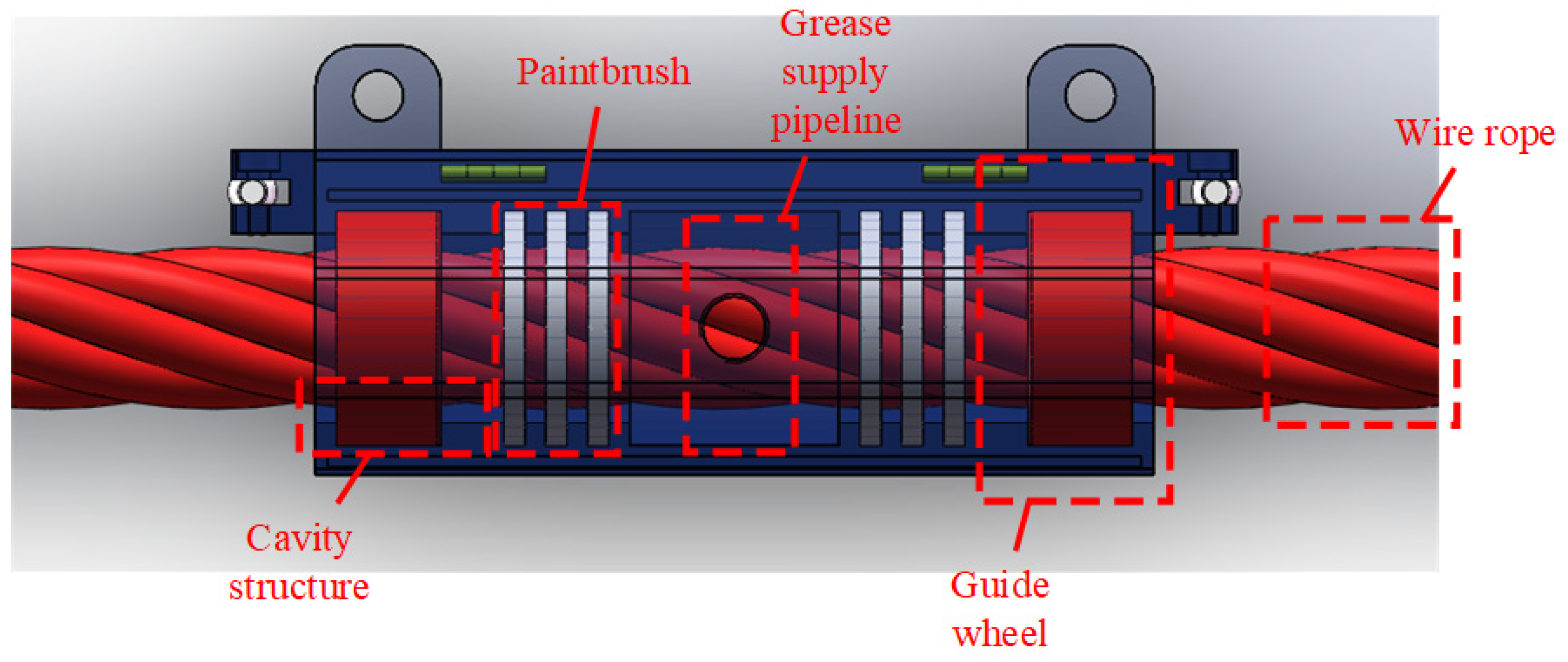
3.3. Greasing and Scraping Unit
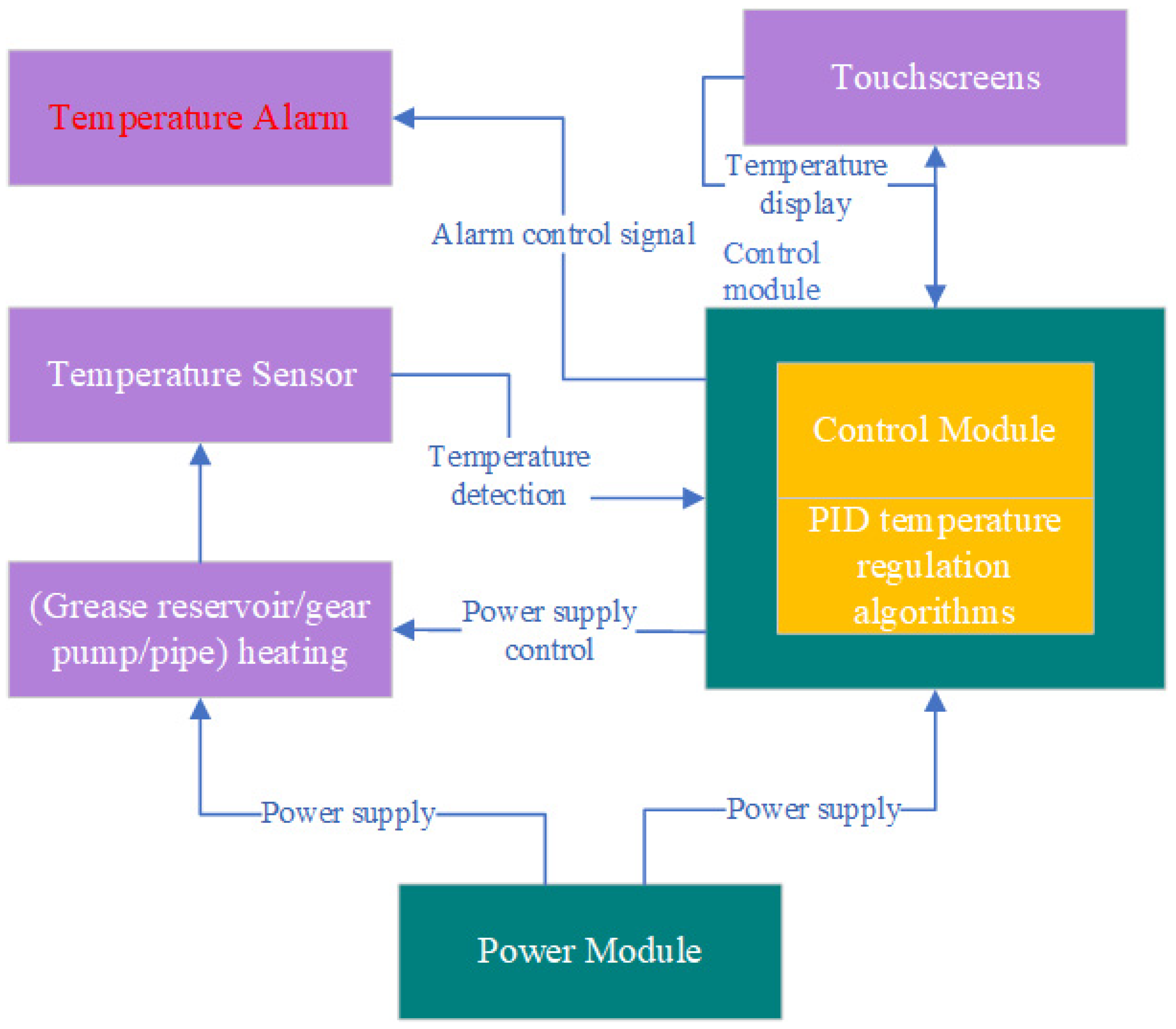
3.4. Intelligent Control Mechanism
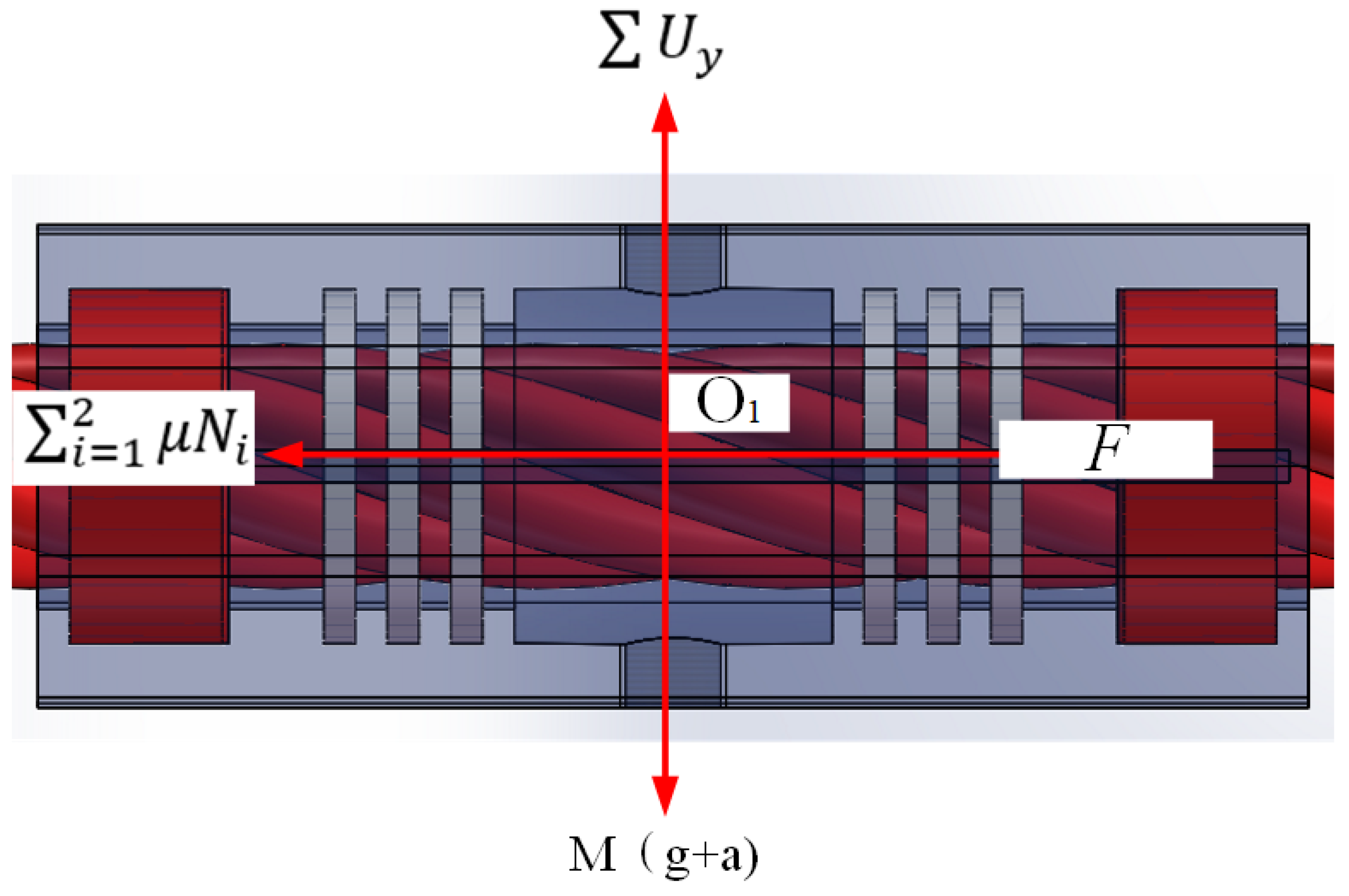
4. Static Analysis of Greasing Device
4.1. Kinematic Analysis
4.2. Grease Consumption
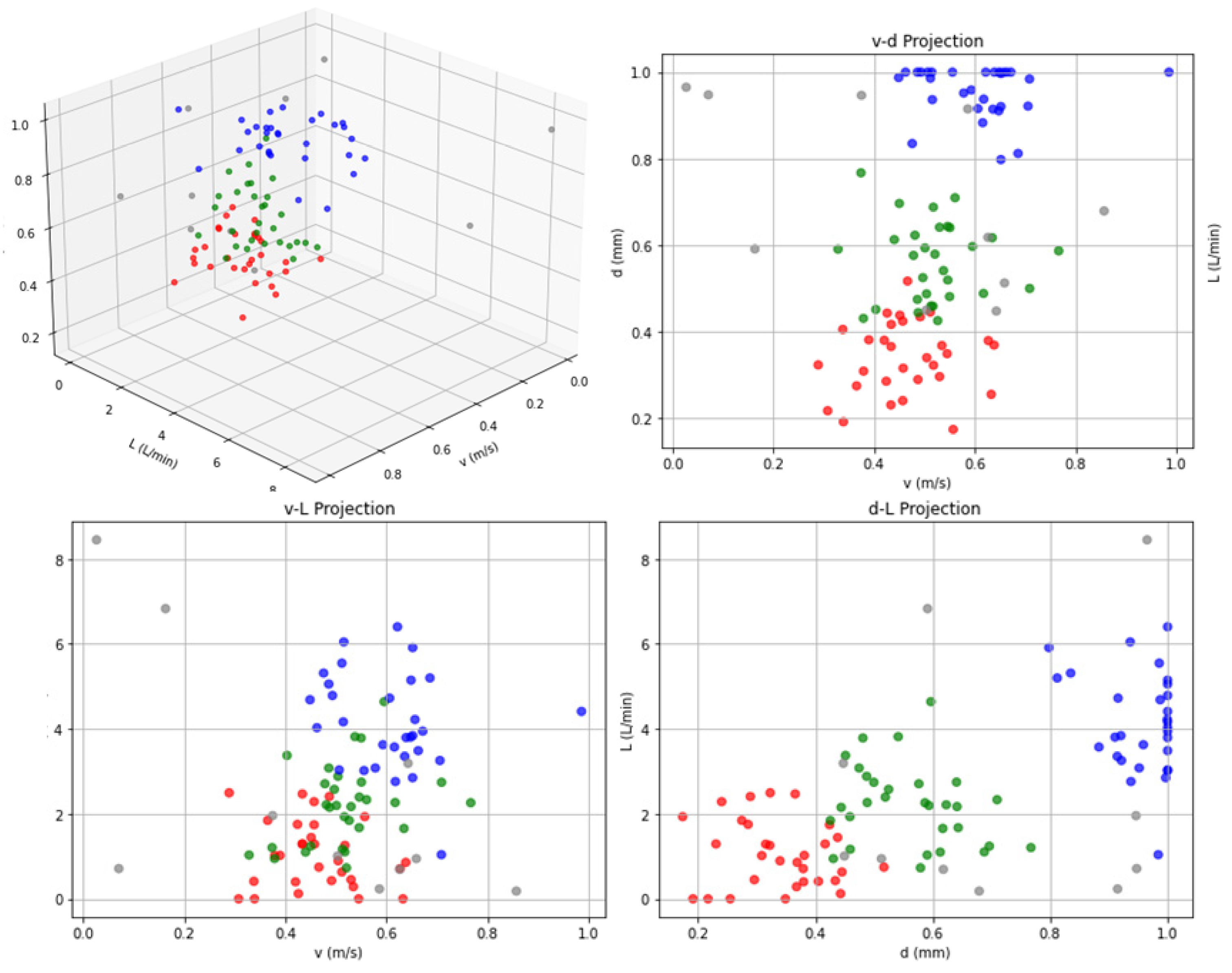
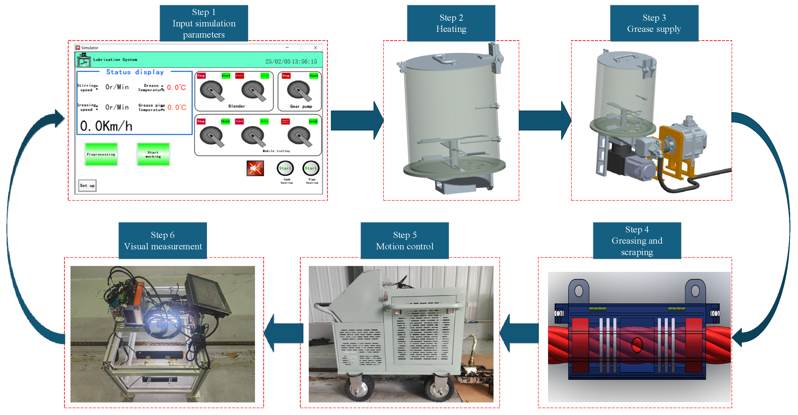
5. Experimental Verification
5.1. Experimental Content
5.2. Determination of Greasing Process Parameters
5.3. Experimental Process
5.4. Experimental Results
6. Conclusions
Author Contributions
Funding
Institutional Review Board Statement
Informed Consent Statement
Data Availability Statement
Conflicts of Interest
References
- Peng, Y.; Huang, K.; Ma, C.; Zhu, Z.; Chang, X.; Lu, H.; Zhang, Q.; Xu, C. Friction and wear of multiple steel wires in a wire rope. Friction 2023, 11, 763–784. [Google Scholar] [CrossRef]
- Zhou, P.; Zhou, G.; Han, L.; Yan, X.; Wang, H.; He, Z. Failure analysis for hoisting wire ropes with local accumulated broken wire damage on the surface. J. Mech. Sci. Technol. 2023, 37, 3459–3468. [Google Scholar] [CrossRef]
- Han, J.; Zhang, Y.; Feng, Z.; Zhao, L. Research on intelligent identification algorithm for steel wire rope damage based on residual network. Appl. Sci. 2024, 14, 3753. [Google Scholar] [CrossRef]
- Mazurek, P. A comprehensive review of steel wire rope degradation mechanisms and recent damage detection methods. Sustainability 2023, 15, 5441. [Google Scholar] [CrossRef]
- Shahzada, N.S. Damage and Failure of Steel Wire Ropes; Politecnico di Torino: Torino, Italy, 2022. [Google Scholar]
- Liu, S.; Sun, Y.; He, L.; Kang, Y. Weak signal processing methods based on improved HHT and filtering techniques for steel wire rope. Appl. Sci. 2022, 12, 6969. [Google Scholar] [CrossRef]
- Čereška, A.; Zavadskas, E.K.; Bucinskas, V.; Podvezko, V.; Sutinys, E. Analysis of steel wire rope diagnostic data applying multi-criteria methods. Appl. Sci. 2018, 8, 260. [Google Scholar] [CrossRef]
- Xu, F.; Jiang, Z.; Jiang, Q.; Wang, X.S. Damage detection and assessment of broken wires in cables of a bridge based on magnetic flux leakage. Exp. Tech. 2023, 47, 907–920. [Google Scholar] [CrossRef]
- Zhou, P.; Zhou, G.; Wang, H.; Wang, D.; He, Z. Automatic detection of industrial wire rope surface damage using deep learning-based visual perception technology. IEEE Trans. Instrum. Meas. 2020, 70, 1–11. [Google Scholar] [CrossRef]
- Li, L.-J.; Zhang, X.G. Discrimination method of wire rope fault signal based on Holzer sensor for multi array weak magnetic detection. Clust. Comput. 2019, 22 (Suppl. 2), 4901–4906. [Google Scholar] [CrossRef]
- Zhang, D.; Zhang, E.; Yan, X. Quantitative method for detecting internal and surface defects in wire rope. NDT E Int. 2021, 119, 102405. [Google Scholar] [CrossRef]
- Lee, Y.-J.; Lee, K.-S. A development of the fault detection system of wire rope using magnetic flux leakage inspection method and noise filter. Trans. Korean Inst. Electr. Eng. 2019, 63, 418–424. [Google Scholar] [CrossRef]
- Zhao, D.; Liu, Y.X.; Ren, X.T.; Gao, J.Z.; Liu, S.G.; Dong, L.Q.; Cheng, M.S. Fatigue life prediction of wire rope based on grey particle filter method under small sample condition. Eksploat. I Niezawodn. 2021, 23, 454–467. [Google Scholar] [CrossRef]
- Chang, X.D.; Huang, H.B.; Peng, Y.X.; Li, S.X. Friction, wear and residual strength properties of steel wire rope with different corrosion types. Wear 2020, 458, 203425. [Google Scholar] [CrossRef]
- Ribeiro, R.; Silva, F.J.G.; Pinto, A.G.; Campilho, R.D.S.G.; Pinto, H.A. Designing a novel system for the introduction of lubricant in control cables for the automotive industry. Procedia Manuf. 2019, 38, 715–725. [Google Scholar] [CrossRef]
- Huang, K.; Peng, Y.; Dong, Y.; Chang, X.; Zhou, Z.; Lu, H.; Tang, W.; Wang, G.; Zhang, Q. Friction and wear behavior of multiple steel wires with different corrosion extents under different lubrication conditions. Wear 2023, 524, 204889. [Google Scholar] [CrossRef]
- Halim, M.; Chandra, H.; Pratiwi, D.K.; Zahir, M. Sustainable development of lubricator to optimization process of lubrication in wire rope sling. J. Phys. Conf. Ser. 2019, 1198, 042006. [Google Scholar] [CrossRef]
- Zhang, Y.; Zhang, Q.; Peng, Y.; Wang, C.; Chang, X.; Chen, G. Preparation and tribological properties of lanthanum stearate modified lubricating oil for wire rope in a mine hoist. Materials 2021, 14, 5821. [Google Scholar] [CrossRef]
- Zhang, Q.; Peng, Y.; Chang, X.; Zhou, X.; Zhang, Y.; Chen, G.; Lu, H. Tribological performances of α-ZrP as the additive of the grease used for mine hoisting wire rope. Wear 2022, 504, 204428. [Google Scholar] [CrossRef]
- Feng, C.; Zhang, D.; Grecov, D.; Chen, K. Effect of rheological properties of friction-enhancing greases on the friction between friction lining and wire rope. Tribol. Int. 2020, 144, 106143. [Google Scholar] [CrossRef]
- Xu, C.; Peng, Y.; Zhu, Z.; Tang, W.; Huang, K. Fretting behavior evolution of steel wires with helical structure after adding ore particles in lubricating grease. Eng. Fail. Anal. 2021, 124, 105332. [Google Scholar] [CrossRef]
- Fang, G.; Cheng, J. Design and implementation of a wire rope climbing robot for sluices. Machines 2022, 10, 1000. [Google Scholar] [CrossRef]
- Fu, C.; Wang, H.; Tang, L. The design of decontamination unit for wire rope auto cleaning and detecting system. Adv. Mater. Res. 2014, 889, 413–416. [Google Scholar] [CrossRef]
- Madanhire, I.; Mushiri, T.; Mbohwa, C. Improved wire rope lubricator design for a mine. In Proceedings of the International Conference on Industrial Engineering and Operations Management, Rabat, Morocco, 11–13 April 2017; pp. 263–271. [Google Scholar]
- Wang, W.; Yang, H.; Chen, Y.; Huang, X.; Cao, J.; Zhang, W. Motion analysis of wire rope maintenance device. Actuators 2023, 12, 392. [Google Scholar] [CrossRef]
- Chen, J.J.; Wang, H.; Lin, J.S.; Fu, C.; Tang, L. The decontaminating device in steel wire rope automatic cleaning, detection and maintenance integration system. Appl. Mech. Mater. 2014, 483, 382–385. [Google Scholar] [CrossRef]
- Gao, Y.F.; Li, G.P.; Jiang, C.D.; Li, Y.J. Design of the wire rope cleaning and detection line control system based on touch screen and PLC. Appl. Mech. Mater. 2014, 455, 495–501. [Google Scholar] [CrossRef]
- Belmas, I.V.; Bilous, O.I.; Tantsura, G.I.; Shvachka, A.V. Development of a system for continuous automatic monitoring of the cable rope condition. Strength Mater. 2022, 54, 825–840. [Google Scholar] [CrossRef]
- GB/T 3142-2019; Standard Test Method for Determination of Load-Carrying Capacity of Lubricants-Four-Ball Method. National Standard of the People’s Republic of China, State Administration for Market Regulation: Beijing, China, 2019.
- ISO 12925-1:2018; Lubricants, Industrial Oils, and Related Products—Part 1: Specifications for Lubricants for Wire Ropes. International Organization for Standardization: Geneva, Switzerland, 2018.
- DIN Deutsches Institut für Normung e.V. DIN 51817; Testing of Lubricants—Determination of Oil Separation from Greases Under Static Conditions. Beuth Verlag GmbH: Berlin, Germany, 2014.


| Test Item | Specialty Grease | Conventional Grease | Standard Requirement | Conclusion |
|---|---|---|---|---|
| Worked penetration (0.1 mm) | 355 | 310–330 (NLGI Grade 1) | NLGI Grade 0 (335–385) | ↑ Ultra-soft texture, enhances penetration into wire strands. |
| Dropping point (°C) | 190 | 160–180 | ≥180 | ↑ Thermal stability (exceeds conventional by 10–30 °C). |
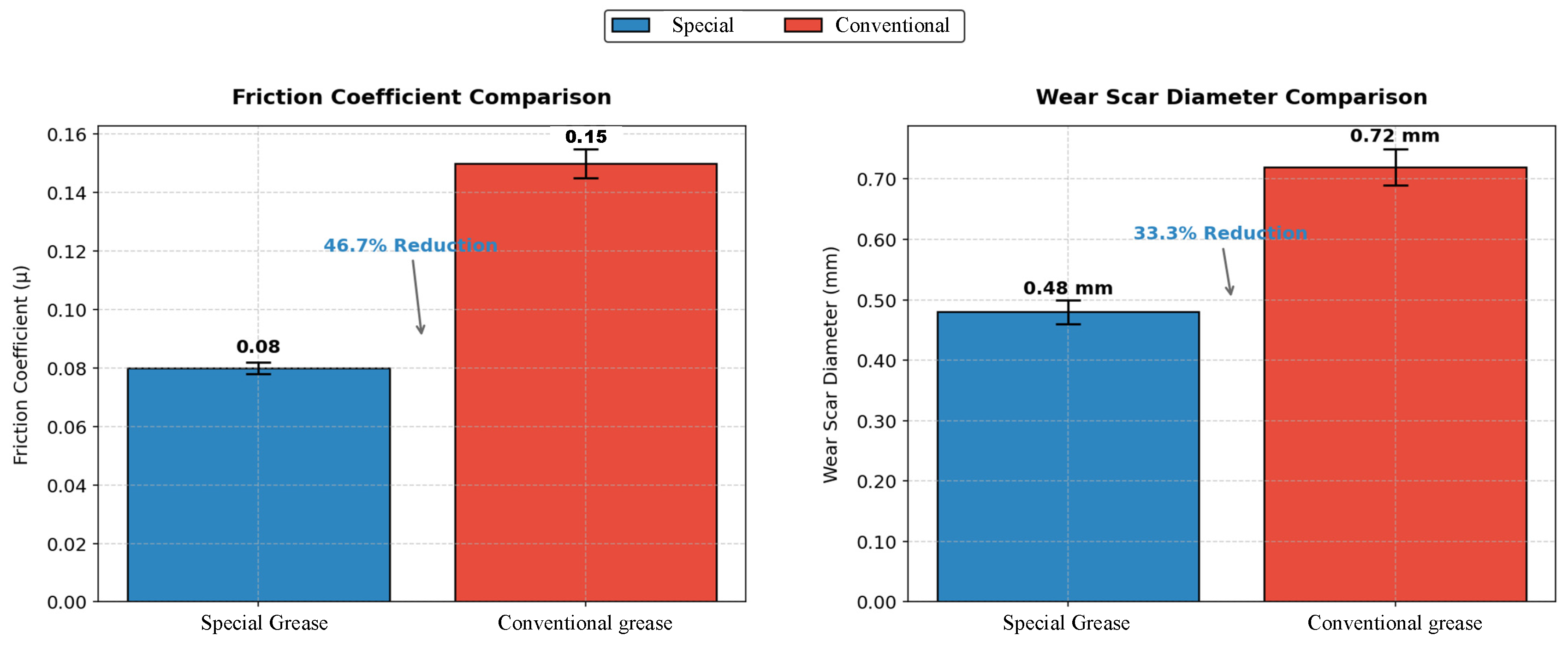
| Four-ball WSD (mm) | 0.48 | 0.65–0.80 | ≤0.60 | ↓ 33% smaller wear scar, superior EP/anti-wear performance. |
| Copper strip corrosion | Class 1a | Class 2–3 | No green discoloration | ↑ Metal compatibility, minimal corrosive effects. |
| Evaporation loss (%) (180 °C) | 1.05 | 2.0–3.5 | ≤2.0 (typical) | ↓ 47% lower loss, reduced environmental contamination. |
| Serial Number | Temp | Thickness of Grease Application | Travel Distance (Maximum 60 mm) |
|---|---|---|---|
| 40 °C-1 | 40 °C | 1 mm | 0 mm |
| 40 °C-2 | 40 °C | 1 mm | 0 mm |
| 40 °C-3 | 40 °C | 3 mm | 0 mm |
| 40 °C-4 | 40 °C | 3 mm | 0 mm |
| 50 °C-1 | 50 °C | 1 mm | 0 mm |
| 50 °C-2 | 50 °C | 1 mm | 0 mm |
| 50 °C-3 | 50 °C | 3 mm | 6 mm |
| 50 °C-4 | 50 °C | 3 mm | 4 mm |
| 60 °C-1 | 60 °C | 1 mm | 3 mm |
| 60 °C-2 | 60 °C | 1 mm | 5.5 mm |
| 60 °C-3 | 60 °C | 3 mm | 60 mm |
| 60 °C-4 | 60 °C | 3 mm | 60 mm |
| 70 °C-1 | 70 °C | 1 mm | 60 mm |
| 70 °C-2 | 70 °C | 1 mm | 60 mm |
| 70 °C-3 | 70 °C | 3 mm | 60 mm |
| 70 °C-4 | 70 °C | 3 mm | 60 mm |
| TestProtocol | 1. Apply the sample grease to the designated area of the metal plate with specified thicknesses (1 mm and 3 mm). 2. Place the grease-coated metal plate into an oven and maintain constant temperatures at 40 °C, 50 °C, 60 °C, and 70 °C for 15 min. 3. Immediately remove the metal plate from the oven, position it vertically, and measure the flow distance of the grease within 1 min. | ||
| a (m/s2) | M (Kg) | μ | g (m/s2) | L1 + L2 + L3 (mm) | L3 (mm) | ∂ (°) | N1 (N) | F (N) |
|---|---|---|---|---|---|---|---|---|
| 0.64 | 20 | 0.6 | 9.8 | 30 | 20 | 30 | 119.4 | 143.5 |
| 2.05 | 20 | 0.6 | 9.8 | 30 | 20 | 30 | 135.5 | 162.6 |
| 3.72 | 20 | 0.6 | 9.8 | 30 | 20 | 30 | 154.6 | 185.5 |
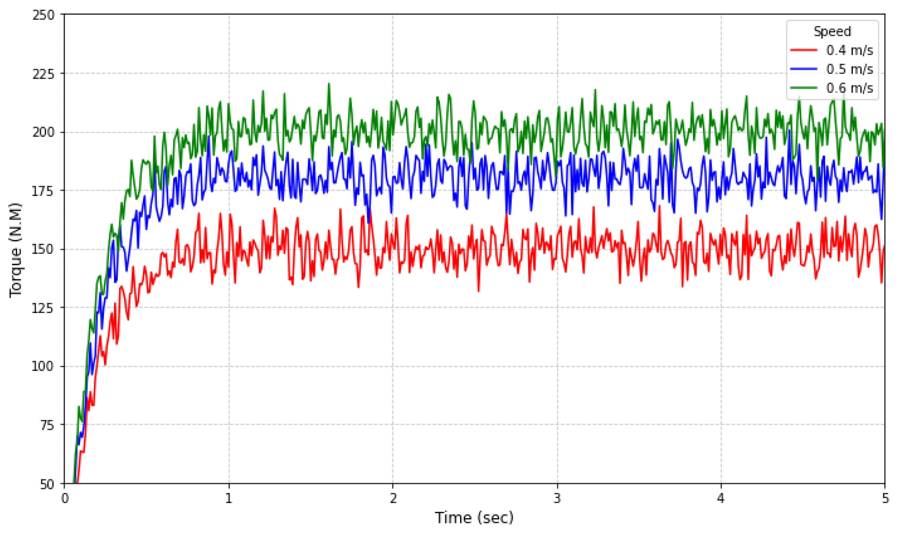
| Startup Speed | Traction Force |
|---|---|
| 0.4 m/s | 148.7 N |
| 0.5 m/s | 177.6 N |
| 0.6 m/s | 201.3 N |
| vmin (m/s) | vmax (m/s) | Lmin (L/min) | Lmax (L/min) | t1max (s) | vt1 (m) | dw (mm) |
|---|---|---|---|---|---|---|
| 0 | 1 | 0 | 10 | 60 | 20 | 36.5 |
| Discharge Volume (cc/rev) | Pressure (kgf/cm2) | Speed (rpm) | Weight (kg) | Remarks | |
|---|---|---|---|---|---|
| 4 | Work | Tallest | 800–4500 | 1.67 | / |
| 210 | 250 | ||||
| Base Oil | Thickener | Dropping Point (°C) | Worked Penetration (0.1 mm) | Adhesion (L/min) | Preheating Temperature (°C) |
|---|---|---|---|---|---|
| Synthetic hydrocarbon | Metallic soap | 190 | 355 | High | 50 |
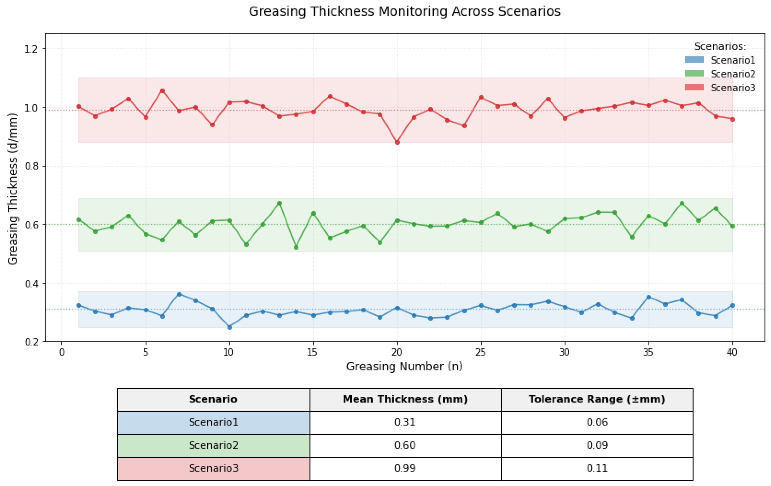
| Scenario | Greasing Time (s) | Greasing Speed (m/s) | Greasing Thickness (mm) | Grease FLOW Rate(L/min) | Greased Diameter (mm) | Grease Consumption (L) | Grease Supply Speed (r/min) |
|---|---|---|---|---|---|---|---|
| 1 | 44.4 | 0.48 | 0.35 | 0.93 | 37.2 | 0.69 | 233 |
| 2 | 39 | 0.52 | 0.57 | 1.92 | 37.54 | 1.25 | 480 |
| 3 | 33.6 | 0.60 | 0.98 | 4.32 | 38.46 | 2.42 | 1080 |
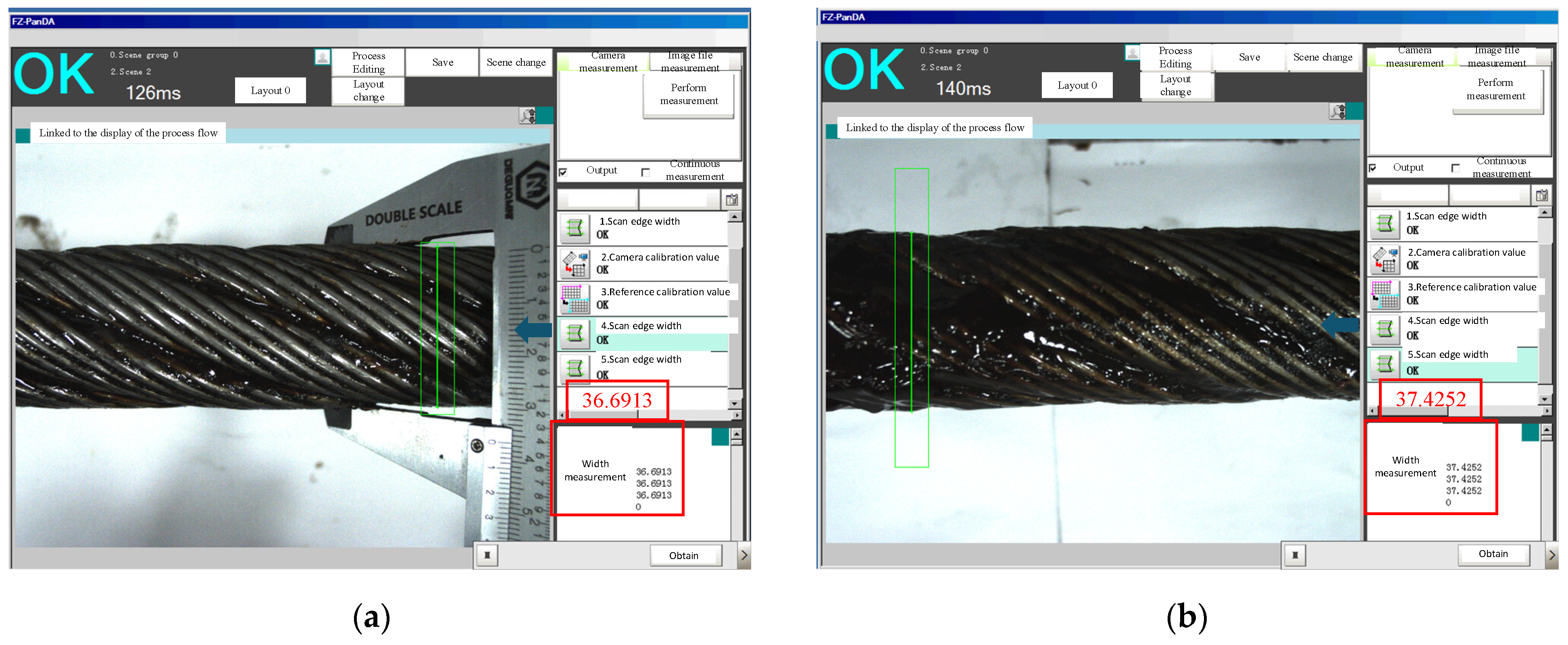
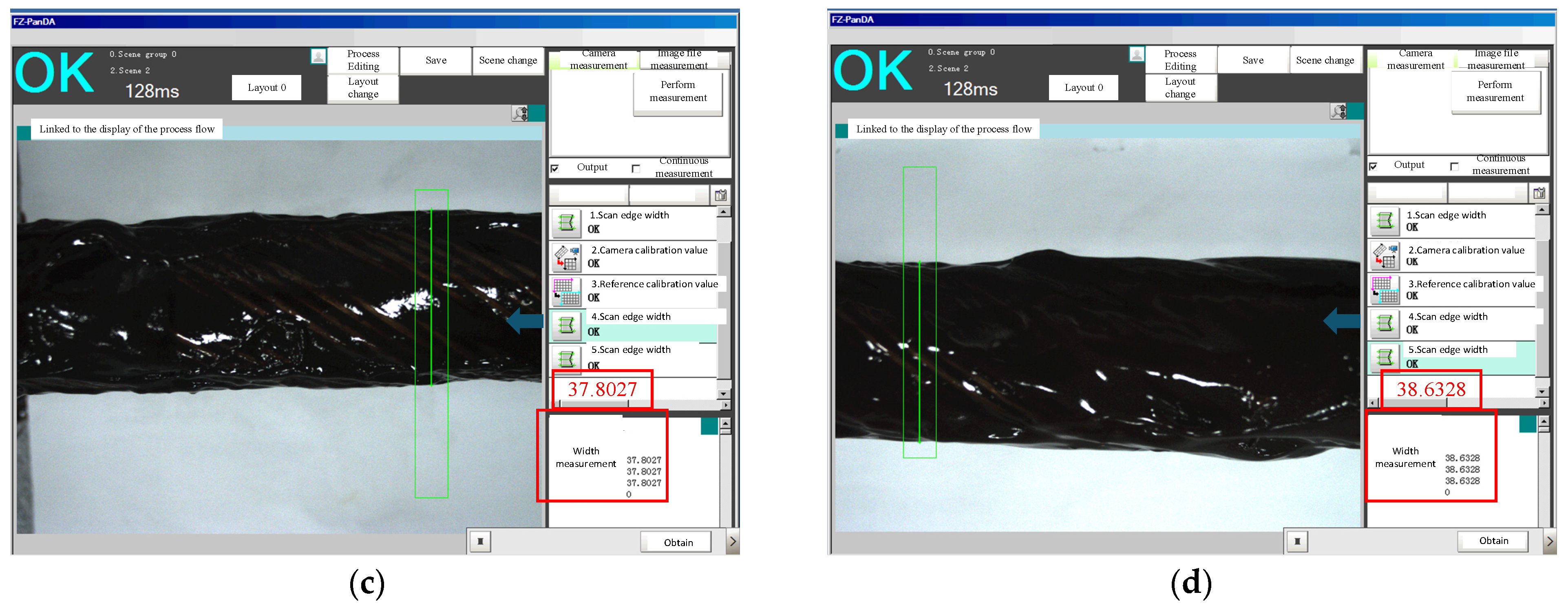
| Scenario Number | Greasing Time (s) | Greasing Speed (m/s) | Greased Diameter (mm) | Thickness of Greasing (mm) | Grease Supply Speed (r/min) |
|---|---|---|---|---|---|
| 1 | 35 | 0.57 | 37.4252 | 0.37 | 300 |
| 2 | 38 | 0.52 | 37.8027 | 0.56 | 500 |
| 3 | 36 | 0.55 | 38.6328 | 0.97 | 1200 |
| Metric | Proposed Device | Hoist-Based Systems [22] | Spray Lubrication [23] | Robotic Platforms [24,25,26] |
|---|---|---|---|---|
| Traction force | <200 N | >300 N (inferred from [22]) | N/A | 200–300 N (motor-driven) |
| Operational speed | 0.6 m/s | 0.3–0.5 m/s (manual) | N/A | 0.4–0.8 m/s |
| Lubricant consumption | Low (directional scraping + sealed chamber) | High (inefficient scraping) | High (15–20% waste) | Moderate (module-dependent) |
Disclaimer/Publisher’s Note: The statements, opinions and data contained in all publications are solely those of the individual author(s) and contributor(s) and not of MDPI and/or the editor(s). MDPI and/or the editor(s) disclaim responsibility for any injury to people or property resulting from any ideas, methods, instructions or products referred to in the content. |
© 2025 by the authors. Licensee MDPI, Basel, Switzerland. This article is an open access article distributed under the terms and conditions of the Creative Commons Attribution (CC BY) license (https://creativecommons.org/licenses/by/4.0/).
Share and Cite
Zhou, F.; Wang, Y.; Gong, R. Research on the Design of an On-Line Lubrication System for Wire Ropes. Sensors 2025, 25, 2695. https://doi.org/10.3390/s25092695
Zhou F, Wang Y, Gong R. Research on the Design of an On-Line Lubrication System for Wire Ropes. Sensors. 2025; 25(9):2695. https://doi.org/10.3390/s25092695
Chicago/Turabian StyleZhou, Fan, Yuemin Wang, and Ruqing Gong. 2025. "Research on the Design of an On-Line Lubrication System for Wire Ropes" Sensors 25, no. 9: 2695. https://doi.org/10.3390/s25092695
APA StyleZhou, F., Wang, Y., & Gong, R. (2025). Research on the Design of an On-Line Lubrication System for Wire Ropes. Sensors, 25(9), 2695. https://doi.org/10.3390/s25092695