
Optimized Magnetization Distribution in Body-Centered Cubic Lattice-Structured Magnetoelastomer for High-Performance 3D Force–Tactile Sensors

 , , and
Abstract
1. Introduction
2. Materials and Methods
2.1. Materials
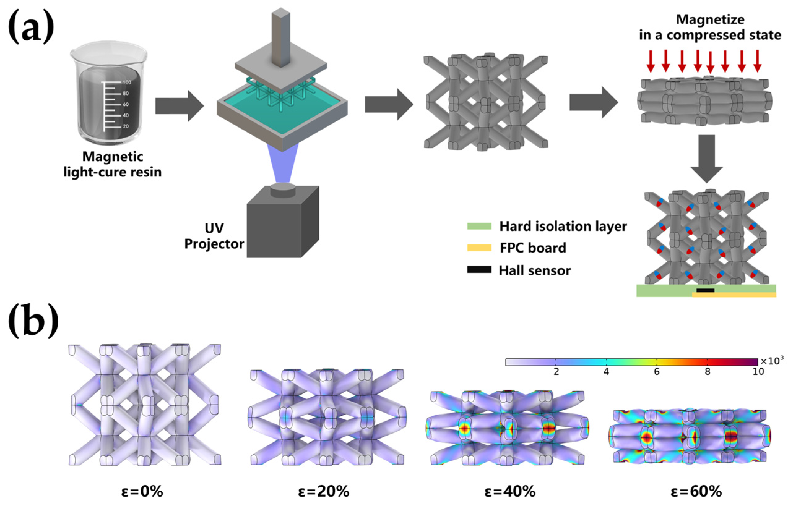
2.2. Manufacture of BLSM
2.3. Preparation of the Magnetic Tactile Sensor
2.4. Characterization
2.5. Computational Simulations
3. Results
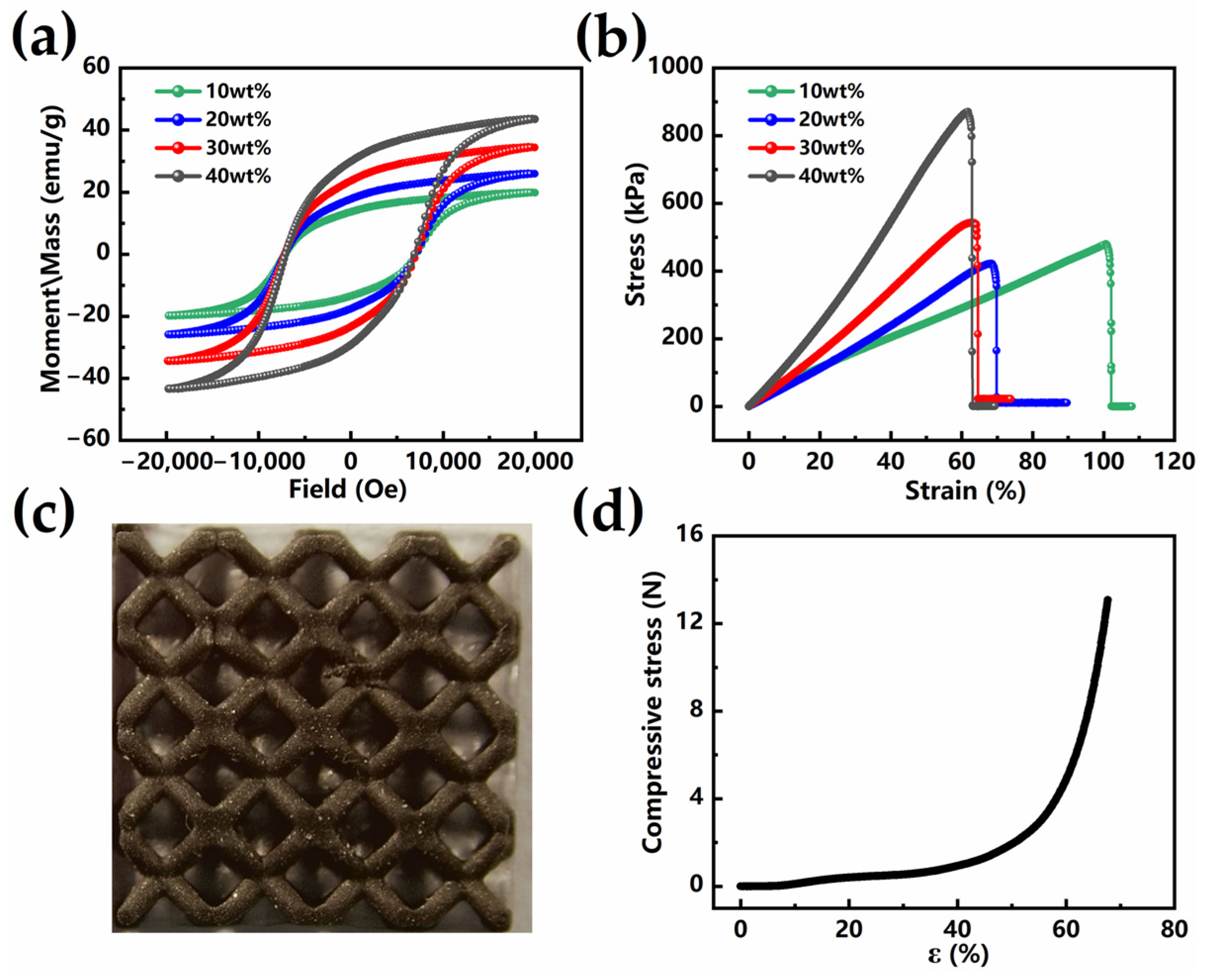
3.1. Magnetic and Mechanical Properties of Magnetic Composite Material
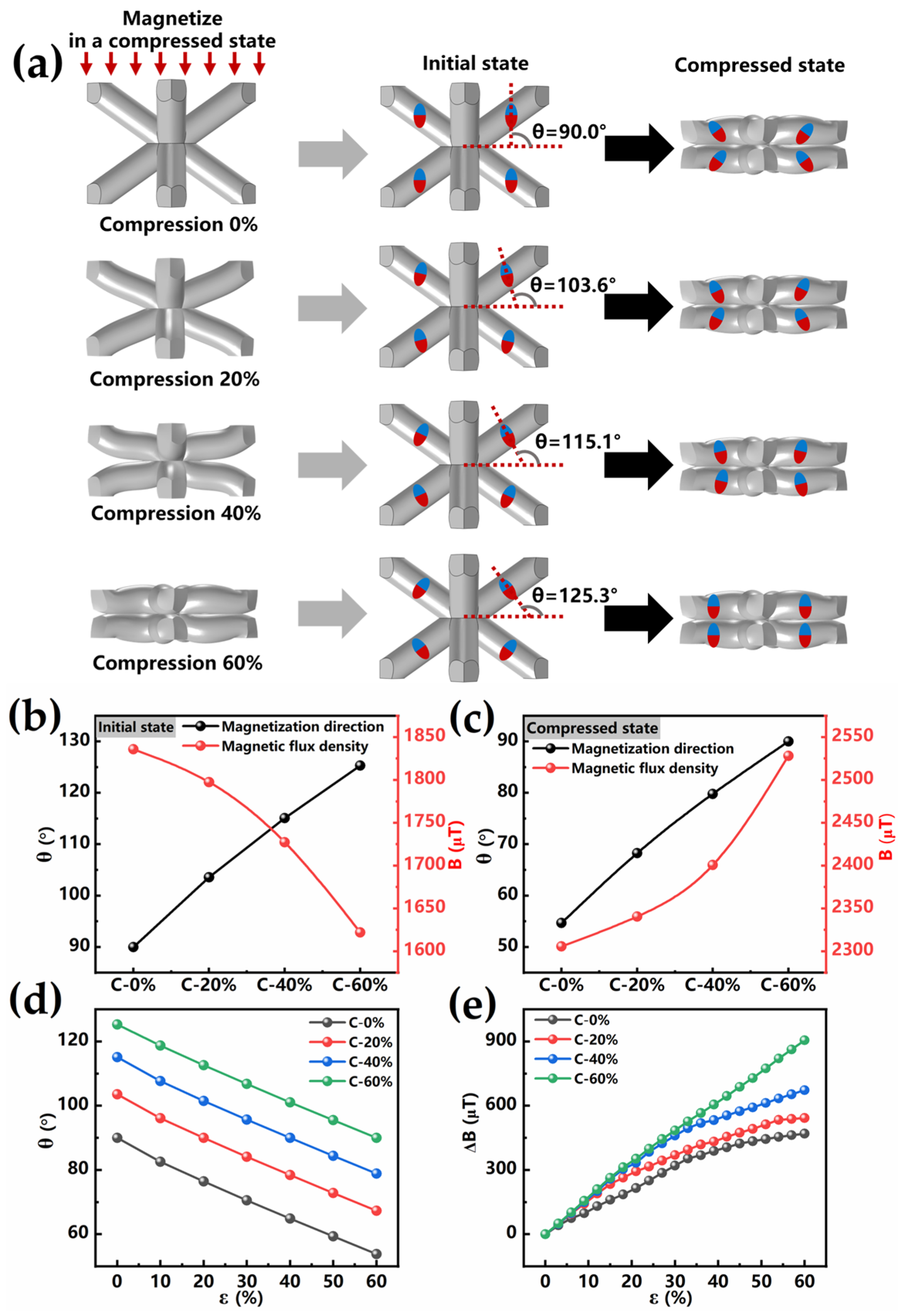
3.2. The Effect of Magnetization on the Force–Magnetic Conversion Performance of BLSM in Compression State
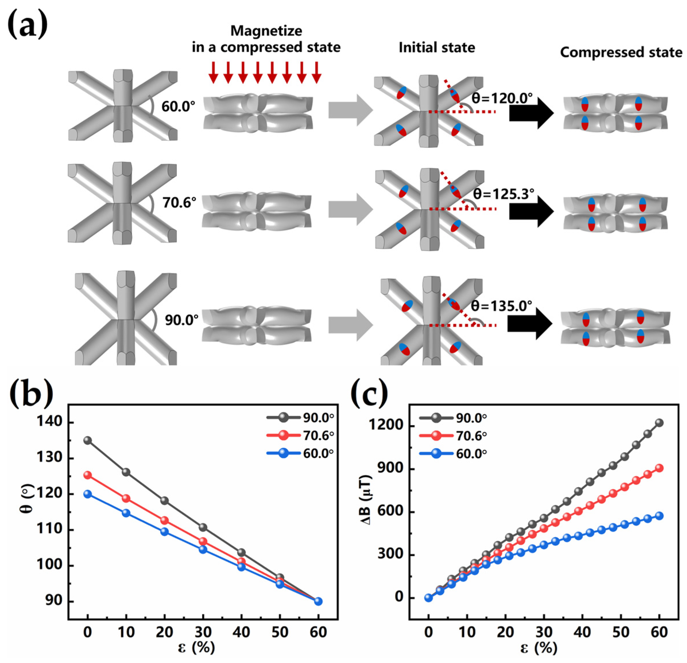
3.3. The Influence of BLSM Structure Parameters on the Force–Magnetic Conversion Performance
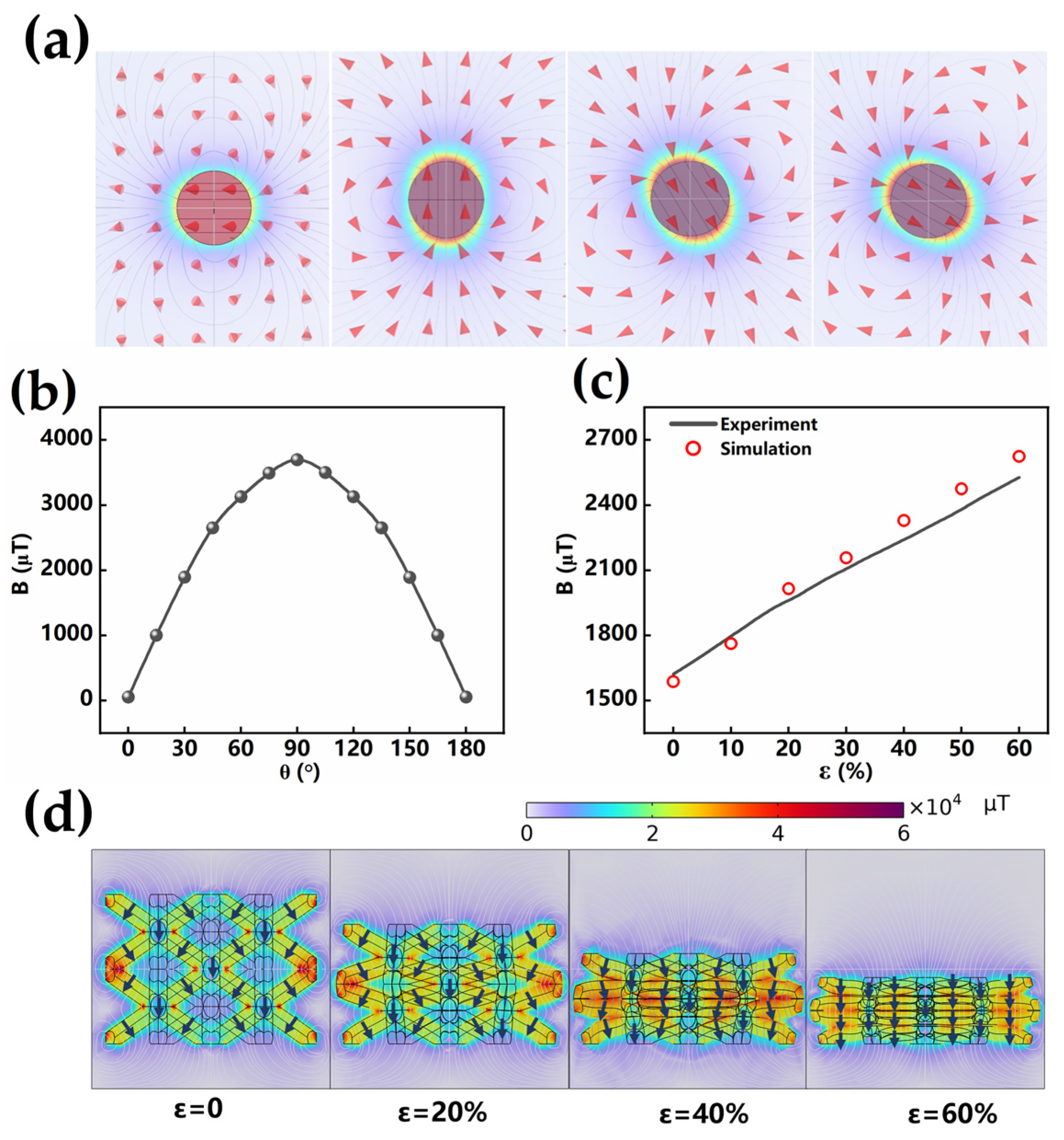
3.4. Mechanism Analysis
4. Application
5. Conclusions
Supplementary Materials
Author Contributions
Funding
Institutional Review Board Statement
Informed Consent Statement
Data Availability Statement
Conflicts of Interest
References
- Fairbanks, M.S.; McCarthy, D.N.; Scott, S.A.; Brown, S.A.; Taylor, R.P. Fractal Electronic Devices: Simulation and Implementation. Nanotechnology 2011, 22, 365304. [Google Scholar] [CrossRef]
- Fan, J.A.; Yeo, W.H.; Su, Y.W.; Hattori, Y.; Lee, W.; Jung, S.Y.; Zhang, Y.H.; Liu, Z.J.; Cheng, H.Y.; Falgout, L.; et al. Fractal Design Concepts for Stretchable Electronics. Nat. Commun. 2014, 5, 3266. [Google Scholar]
- Harris, K.D.; Elias, A.L.; Chung, H.J. Flexible Electronics under Strain: A Review of Mechanical Characterization and Durability Enhancement Strategies. J. Mater.Sci. 2016, 51, 2771–2805. [Google Scholar]
- Dahiya, R.S.; Metta, G.; Valle, M.; Sandini, G. Tactile Sensing-from Humans to Humanoids. IEEE Trans. Robot. 2010, 26, 1–20. [Google Scholar] [CrossRef]
- Viry, L.; Levi, A.; Totaro, M.; Mondini, A.; Mattoli, V.; Mazzolai, B.; Beccai, L. Flexible Three-Axial Force Sensor for Soft and Highly Sensitive Artificial Touch. Adv. Mater. 2014, 26, 2659–2664. [Google Scholar] [CrossRef]
- Qiu, Y.; Wang, F.; Zhang, Z.; Shi, K.; Song, Y.; Lu, J.; Xu, M.; Qian, M.; Zhang, W.; Wu, J.; et al. Quantitative Softness and Texture Bimodal Haptic Sensors for Robotic Clinical Feature Identification and Intelligent Picking. Sci. Adv. 2024, 10, eadp0348. [Google Scholar]
- Bai, N.N.; Xue, Y.H.; Chen, S.Q.; Shi, L.; Shi, J.L.; Zhang, Y.; Hou, X.Y.; Cheng, Y.; Huang, K.X.; Wang, W.D.; et al. A Robotic Sensory System with High Spatiotemporal Resolution for Texture Recognition. Nat. Commun. 2023, 14, 7121. [Google Scholar]
- Mao, Q.; Liao, Z.; Yuan, J.; Zhu, R. Multimodal Tactile Sensing Fused with Vision for Dexterous Robotic Housekeeping. Nat. Commun. 2024, 15, 6871. [Google Scholar]
- Wang, S.; Fan, X.; Zhang, Z.; Su, Z.; Ding, Y.; Yang, H.; Zhang, X.; Wang, J.; Zhang, J.; Hu, P. A Skin-Inspired High-Performance Tactile Sensor for Accurate Recognition of Object Softness. ACS Nano 2024, 18, 17175–17184. [Google Scholar] [CrossRef]
- Lee, Y.; Park, J.; Cho, S.; Shin, Y.-E.; Lee, H.; Kim, J.; Myoung, J.; Cho, S.; Kang, S.; Baig, C.; et al. Flexible Ferroelectric Sensors with Ultrahigh Pressure Sensitivity and Linear Response over Exceptionally Broad Pressure Range. ACS Nano 2018, 12, 4045–4054. [Google Scholar]
- Gao, Y.J.; Ota, H.; Schaler, E.W.; Chen, K.; Zhao, A.; Gao, W.; Fahad, H.M.; Leng, Y.G.; Zheng, A.Z.; Xiong, F.R.; et al. Wearable Microfluidic Diaphragm Pressure Sensor for Health and Tactile Touch Monitoring. Adv. Mater. 2017, 29, 1701985. [Google Scholar]
- Su, L.; Xiong, Q.; Wang, H.Y.; Zi, Y.L. Porous-Structure-Promoted Tribo-Induced High-Performance Self-Powered Tactile Sensor toward Remote Human-Machine Interaction. Adv. Sci. 2022, 9, 2203510. [Google Scholar]
- Liu, W.B.; Duo, Y.N.; Liu, J.Q.; Yuan, F.Y.; Li, L.; Li, L.C.; Wang, G.; Chen, B.H.; Wang, S.Q.; Yang, H.; et al. Touchless Interactive Teaching of Soft Robots through Flexible Bimodal Sensory Interfaces. Nat. Commun. 2022, 13, 5030. [Google Scholar]
- Pang, G.Y.; Deng, J.; Wang, F.J.H.; Zhang, J.H.; Pang, Z.B.; Yang, G. Development of Flexible Robot Skin for Safe and Natural Human-Robot Collaboration. Micromachines 2018, 9, 576. [Google Scholar] [CrossRef]
- Nottensteiner, K.; Sachtler, A.; Albu-Schäffer, A. Towards Autonomous Robotic Assembly: Using Combined Visual and Tactile Sensing for Adaptive Task Execution. J. Intell. Robot. Syst. 2021, 101, 49. [Google Scholar]
- Han, S.; Li, S.; Fu, X.; Han, S.H.; Chen, H.Y.; Zhang, L.; Wang, J.; Sun, G.H. Research Progress of Flexible Piezoresistive Sensors Based on Polymer Porous Materials. ACS Sens. 2024, 9, 3848–3863. [Google Scholar]
- Sun, X.G.; Sun, J.H.; Li, T.; Zheng, S.K.; Wang, C.K.; Tan, W.S.; Zhang, J.G.; Liu, C.; Ma, T.J.; Qi, Z.M.; et al. Flexible Tactile Electronic Skin Sensor with 3d Force Detection Based on Porous Cnts/Pdms Nanocomposites. Nano-Micro Lett. 2019, 11, 57. [Google Scholar]
- Lv, C.Y.; Tian, C.C.; Jiang, J.S.; Dang, Y.; Liu, Y.; Duan, X.X.; Li, Q.N.; Chen, X.J.; Xie, M.Y. Ultrasensitive Linear Capacitive Pressure Sensor with Wrinkled Microstructures for Tactile Perception. Adv. Sci. 2023, 10, 2206807. [Google Scholar] [CrossRef]
- Yu, H.B.; Guo, H.J.; Wang, J.A.; Zhao, T.M.; Zou, W.H.; Zhou, P.L.; Xu, Z.; Zhang, Y.Z.; Zheng, J.C.; Zhong, Y.; et al. Skin-Inspired Capacitive Flexible Tactile Sensor with an Asymmetric Structure for Detecting Directional Shear Forces. Adv. Sci. 2024, 11, 2305883. [Google Scholar] [CrossRef]
- Yu, P.; Liu, W.T.; Gu, C.X.; Cheng, X.Y.; Fu, X. Flexible Piezoelectric Tactile Sensor Array for Dynamic Three-Axis Force Measurement. Sensors 2016, 16, 819. [Google Scholar] [CrossRef]
- Zhang, C.Y.; Zhang, R.; Ji, C.; Pei, Z.; Fu, Z.Y.; Liu, Y.; Sang, S.B.; Hao, R.F.; Zhang, Q. Bioinspired Crocodile Skin-Based Flexible Piezoelectric Sensor for Three-Dimensional Force Detection. IEEE Sens. J. 2023, 23, 21050–21060. [Google Scholar]
- Tomo, T.P.; Regoli, M.; Schmitz, A.; Natale, L.; Kristanto, H.; Somlor, S.; Jamone, L.; Metta, G.; Sugano, S. A New Silicone Structure for Uskin-a Soft, Distributed, Digital 3-Axis Skin Sensor and Its Integration on the Humanoid Robot Icub. IEEE Robot. Autom. Lett. 2018, 3, 2584–2591. [Google Scholar]
- Hellebrekers, T.; Kroemer, O.; Majidi, C. Soft Magnetic Skin for Continuous Deformation Sensing. Adv. Intell. Syst. 2019, 1, 1900025. [Google Scholar]
- Rehan, M.; Saleem, M.M.; Tiwana, M.I.; Shakoor, R.I.; Cheung, R. A Soft Multi-Axis High Force Range Magnetic Tactile Sensor for Force Feedback in Robotic Surgical Systems. Sensors 2022, 22, 3500. [Google Scholar] [CrossRef]
- Ge, J.; Wang, X.; Drack, M.; Volkov, O.; Liang, M.; Bermúdez, G.S.C.; Illing, R.; Wang, C.A.; Zhou, S.Q.; Fassbender, J.; et al. A Bimodal Soft Electronic Skin for Tactile and Touchless Interaction in Real Time. Nat. Commun. 2019, 10, 4405. [Google Scholar]
- Hu, X.C.; Zhu, H.; Chen, R.W.; Hu, S.D.; Jia, Z.; Yu, H.H.; Qu, S.X. Design of 3d Magnetic Tactile Sensors with High Sensing Accuracy Guided by the Theoretical Model. Adv. Intell. Syst. 2023, 5, 2200291. [Google Scholar]
- Melzer, M.; Makarov, D.; Calvimontes, A.; Karnaushenko, D.; Baunack, S.; Kaltofen, R.; Mei, Y.; Schmidt, O.G. Stretchable Magnetoelectronics. Nano Lett. 2011, 11, 2522–2526. [Google Scholar] [CrossRef]
- Cai, S.-Y.; Chang, C.-H.; Lin, H.-I.; Huang, Y.-F.; Lin, W.-J.; Lin, S.-Y.; Liou, Y.-R.; Shen, T.-L.; Huang, Y.-H.; Tsao, P.-W.; et al. Ultrahigh Sensitive and Flexible Magnetoelectronics with Magnetic Nanocomposites: Toward an Additional Perception of Artificial Intelligence. ACS Appl. Mater. Interfaces 2018, 10, 17393–17400. [Google Scholar]
- Fernández, E.; Kurlyandskaya, G.V.; García-Arribas, A.; Svalov, A.V. Nanostructured Giant Magneto-Impedance Multilayers Deposited onto Flexible Substrates for Low Pressure Sensing. Nanoscale Res. Lett. 2012, 7, 230. [Google Scholar] [CrossRef] [PubMed]
- Zhang, X.C.; Hu, H.; Tang, D.F.; Zhang, C.Q.; Fu, J.Z.; Zhao, P. Magnetic Flexible Tactile Sensor Via Direct Ink Writing. Sens. Actuator A-Phys. 2021, 327, 112753. [Google Scholar]
- Dai, H.Z.; Zhang, C.Q.; Pan, C.F.; Hu, H.; Ji, K.P.; Sun, H.A.; Lyu, C.; Tang, D.F.; Li, T.F.; Fu, J.Z.; et al. Split-Type Magnetic Soft Tactile Sensor with 3d Force Decoupling. Adv. Mater. 2024, 36, 2310145. [Google Scholar] [CrossRef]
- Yan, Y.C.; Hu, Z.; Yang, Z.B.; Yuan, W.Z.; Song, C.Y.; Pan, J.; Shen, Y.J. Soft Magnetic Skin for Super-Resolution Tactile Sensing with Force Self-Decoupling. Sci. Robot. 2021, 6, eabc8801. [Google Scholar] [CrossRef] [PubMed]
- Ribeiro, P.; Khan, M.A.; Alfadhel, A.; Kosel, J.; Franco, F.; Cardoso, S.; Bernardino, A.; Santos-Victor, J.; Jamone, L. A Miniaturized Force Sensor Based on Hair-Like Flexible Magnetized Cylinders Deposited over a Giant Magnetoresistive Sensor. IEEE Trans. Magn. 2017, 53, 4700205. [Google Scholar] [CrossRef]
- Meier, Y.A.; Duhr, P.; Mordarski, M.; Vergne, C.; Poloni, E.; Studart, A.R.; Pascal, J.; Demiroers, A.F. Magnetic Hair Tactile Sensor for Directional Pressure Detection. Adv. Intell. Syst. 2024, 6, 2400106. [Google Scholar] [CrossRef]
- Man, J.D.; Jin, Z.H.; Chen, J.M. Magnetic Tactile Sensor with Bionic Hair Array for Sliding Sensing and Object Recognition. Adv. Sci. 2024, 11, 2306832. [Google Scholar] [CrossRef] [PubMed]
- Chen, Z.; Sahoo, S.; Pérez-Prado, M.T.; Mordehai, D. The Extended Scaling Laws of the Mechanical Properties of Additively Manufactured Body-Centered Cubic Lattice Structures under Large Compressive Strains. Mech. Mater. 2024, 196, 105075. [Google Scholar] [CrossRef]
- Zhai, H.; Li, X.; Yu, S.; Wang, J.; Chang, Y.; Li, J.; Cheng, X.; Zhou, L.; Fang, Y.; Liu, T. Review on the 3D Printing Technology and Application of Magnetic Materials: Material-Process-Structure-Application. Compos. Part B Eng. 2025, 298, 112387. [Google Scholar] [CrossRef]
- Zhou, Y.; Zhao, X.; Xu, J.; Fang, Y.; Chen, G.; Song, Y.; Li, S.; Chen, J. Giant Magnetoelastic Effect in Soft Systems for Bioelectronics. Nature Mater. 2021, 20, 1670–1676. [Google Scholar] [CrossRef]
- Zhou, Y.; Zhao, X.; Xu, J.; Chen, G.; Tat, T.; Li, J.; Chen, J. A Multimodal Magnetoelastic Artificial Skin for Underwater Haptic Sensing. Sci. Adv. 2024, 10, eadj8567. [Google Scholar] [CrossRef]
- Mohammadi, A.; Xu, Y.; Tan, Y.; Choong, P.; Oetomo, D. Magnetic-Based Soft Tactile Sensors with Deformable Continuous Force Transfer Medium for Resolving Contact Locations in Robotic Grasping and Manipulation. Sensors 2019, 19, 4925. [Google Scholar] [CrossRef]

| Ref. | Sensitivity | Resolution | Range | 3D-Force Sensing |
|---|---|---|---|---|
| [23] | / | 30 mN | 1.9 N | Only direction |
| [24] | 16 mV/N | 100 mN | 20 N | Yes |
| [40] | / | 1.5 N | 10 N | No |
| [32] | / | 10 mN | 10 N | Yes |
| [35] | 6.63 μT/mN | 0.2 mN | 19.5 mN | Only direction |
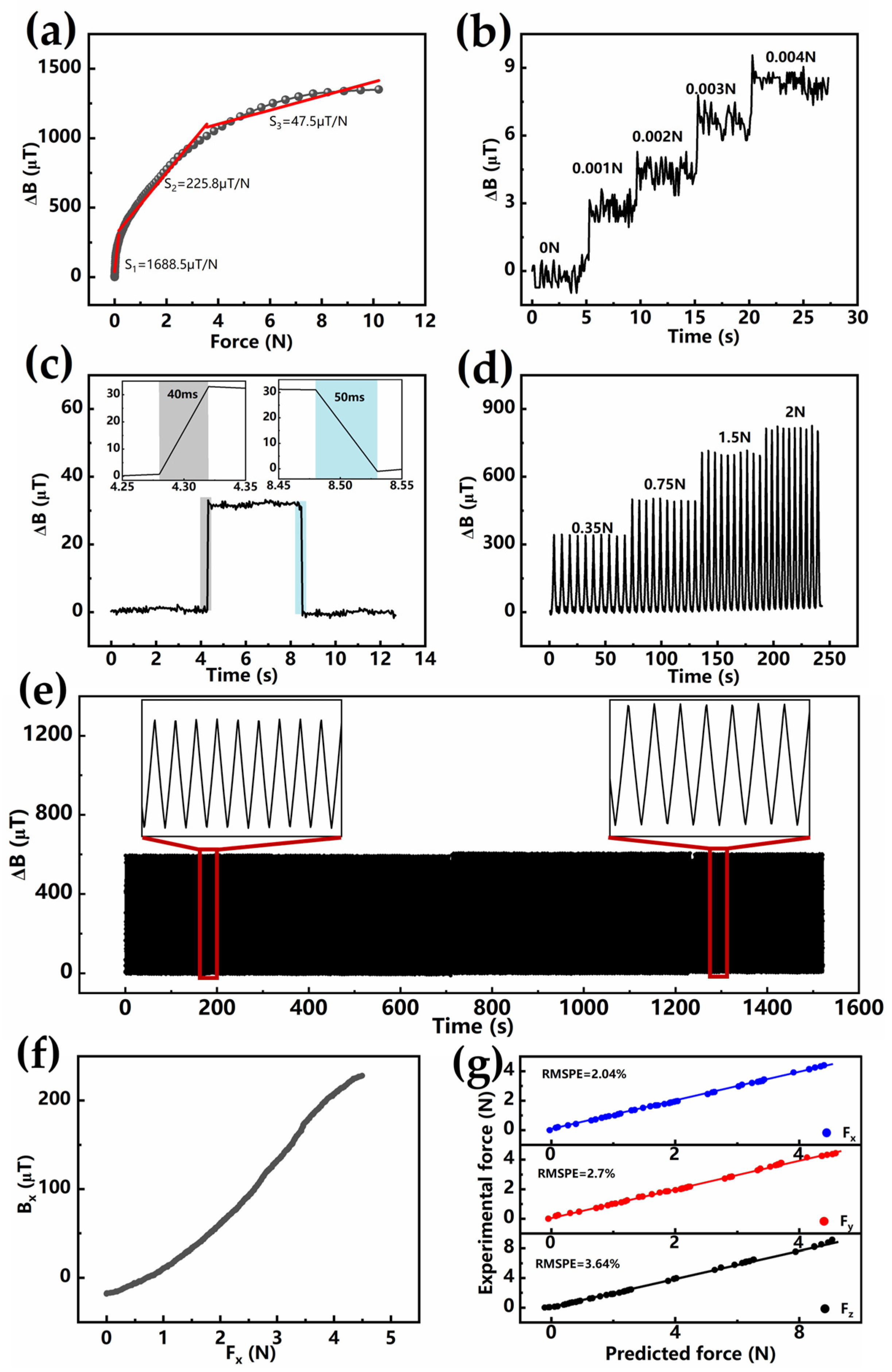
| This work | 1688.5 μT/N | 1 mN | 10 N | Yes |
Disclaimer/Publisher’s Note: The statements, opinions and data contained in all publications are solely those of the individual author(s) and contributor(s) and not of MDPI and/or the editor(s). MDPI and/or the editor(s) disclaim responsibility for any injury to people or property resulting from any ideas, methods, instructions or products referred to in the content. |
© 2025 by the authors. Licensee MDPI, Basel, Switzerland. This article is an open access article distributed under the terms and conditions of the Creative Commons Attribution (CC BY) license (https://creativecommons.org/licenses/by/4.0/).
Share and Cite
Hou, H.; Xiang, Z.; Zhi, C.; Hu, H.; Zhu, X.; Bian, B.; Wu, Y.; Liu, Y.; Yi, X.; Shang, J.; et al. Optimized Magnetization Distribution in Body-Centered Cubic Lattice-Structured Magnetoelastomer for High-Performance 3D Force–Tactile Sensors. Sensors 2025, 25, 2312. https://doi.org/10.3390/s25072312
Hou H, Xiang Z, Zhi C, Hu H, Zhu X, Bian B, Wu Y, Liu Y, Yi X, Shang J, et al. Optimized Magnetization Distribution in Body-Centered Cubic Lattice-Structured Magnetoelastomer for High-Performance 3D Force–Tactile Sensors. Sensors. 2025; 25(7):2312. https://doi.org/10.3390/s25072312
Chicago/Turabian StyleHou, Hongfei, Ziyin Xiang, Chaonan Zhi, Haodong Hu, Xingyu Zhu, Baoru Bian, Yuanzhao Wu, Yiwei Liu, Xiaohui Yi, Jie Shang, and et al. 2025. "Optimized Magnetization Distribution in Body-Centered Cubic Lattice-Structured Magnetoelastomer for High-Performance 3D Force–Tactile Sensors" Sensors 25, no. 7: 2312. https://doi.org/10.3390/s25072312
APA StyleHou, H., Xiang, Z., Zhi, C., Hu, H., Zhu, X., Bian, B., Wu, Y., Liu, Y., Yi, X., Shang, J., & Li, R.-W. (2025). Optimized Magnetization Distribution in Body-Centered Cubic Lattice-Structured Magnetoelastomer for High-Performance 3D Force–Tactile Sensors. Sensors, 25(7), 2312. https://doi.org/10.3390/s25072312