1. Introduction
There are a large number of Potentially Hazardous Asteroids (PHAs) near Earth, posing a serious threat to the safety of the planet and human survival. At present, various asteroid defense methods have been proposed, but most of them are still in the early conceptual research stage [
1]. Due to technological or other limitations, these methods may be difficult to transform into practical scientific tasks for verification in a short period of time. Directly launching impactors for impact is currently the easiest and most mature method to implement [
2]. Kinetic impact refers to the high-speed impact of a spacecraft on an asteroid at a certain angle, causing the asteroid’s orbit to deviate and move away from Earth [
3]. From the aspects of technological maturity and operability, it is considered the simplest and most feasible disposal technology currently available. On 26 September 2022, NASA’s Double Asteroid Redirection Test (DART) probe successfully impacted the target asteroid Dimorphos, causing it to deviate from its original orbit. This was the world’s first successful planetary defense test mission, verifying the feasibility of a kinetic impact technology on planets [
4,
5,
6].
The complex and drastic changes during the high-speed impact of asteroids are difficult to solve directly through analysis, and are mainly studied through numerical simulations and experiments [
7]. Ground experiments are used to verify the effectiveness of simulation results, and to predict experimental results through simulation, guiding the formulation of experimental parameters. At present, numerical simulation methods for high-speed collision dynamics can be divided into gridded methods and meshless methods according to gridding standards [
8]. The gridding method replaces the continuous solution region with a grid composed of a finite number of discrete points, and then uses the difference quotient of grid nodes instead of the derivative, directly transforming the differential equation into an algebraic equation for solution, such as the Lagrangian method and Euler method [
9,
10]. Although grid based numerical methods have achieved great success, they are difficult to use to handle discontinuous problems such as large deformations, motion interfaces, and free surfaces [
11].
The meshless method does not use a pre-defined grid structure to discretize the solution domain, but instead replaces the grid structure with a series of node arrangements [
12]. An approximation related to the weight function is used to represent the physical information on the nodes. A node on the solution domain can affect the mechanical properties of any point on the entire solution domain, thus breaking away from the concept of elements or grids in numerical calculations. Among them, SPH is a classic meshless method that can handle problems with large deformations, deformation boundaries, free surfaces, and motion interfaces [
13,
14,
15]. It has been increasingly widely used in high-speed impact dynamics simulations.
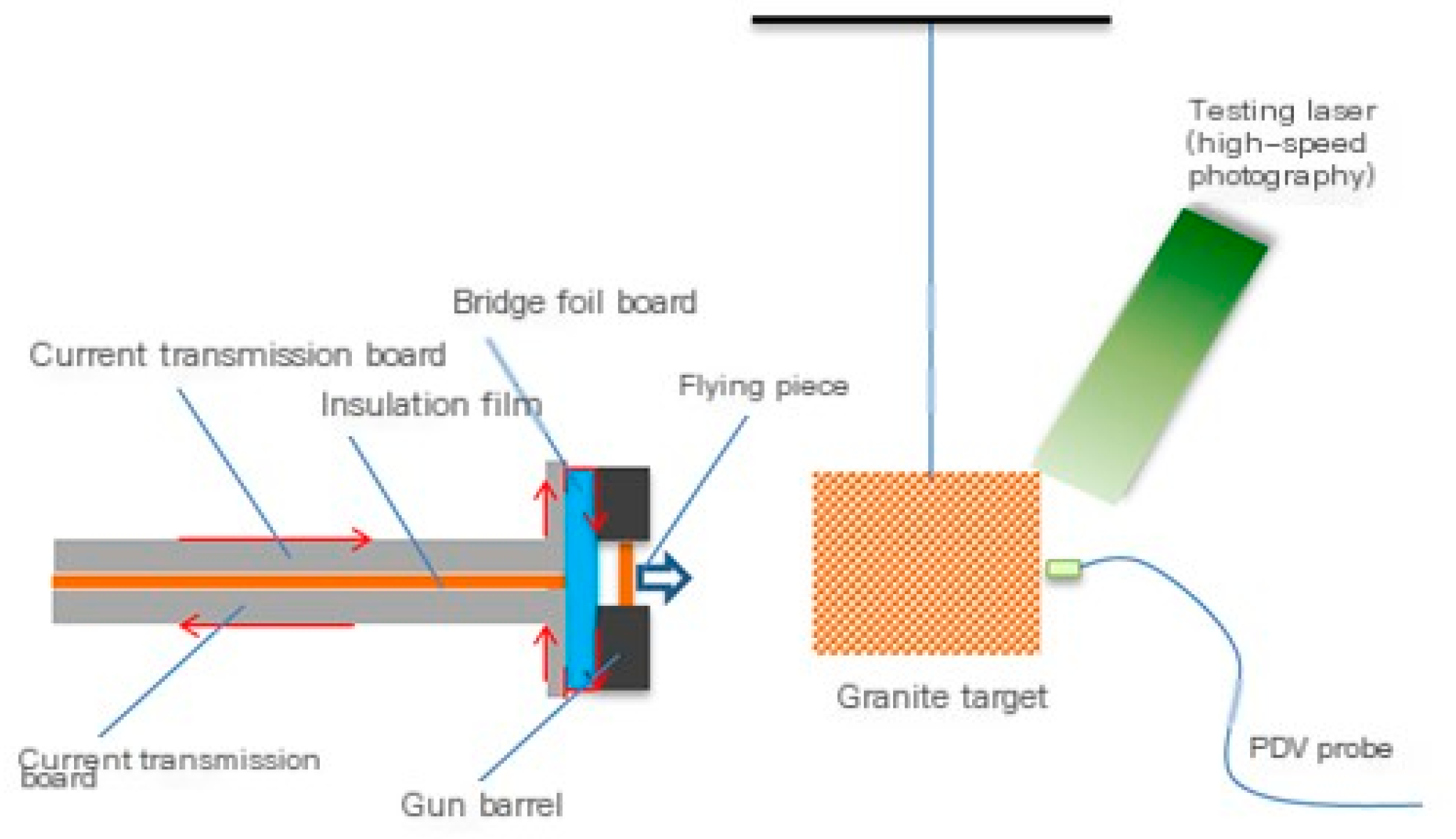
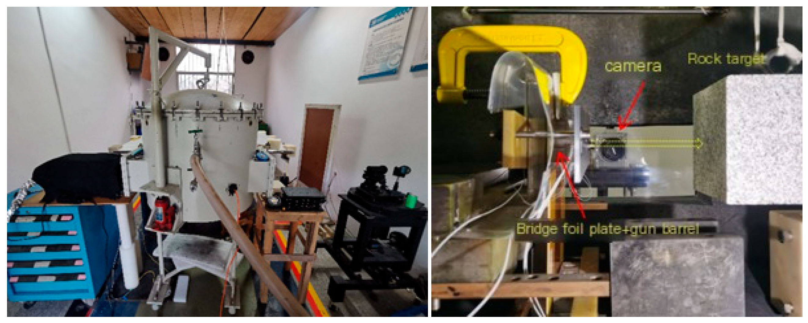
At present, the international technology for achieving ultra-high-speed launches exceeding 10 km/s is very limited, mainly including three-stage light gas guns, electric guns, magnetic driven flyers, and directional energy gathering acceleration technology [
16]. Among them, electric guns are loading devices that use high-pressure gas generated by metal foil electric explosions to drive the ultra-high-speed movement of plastic flyers. Lawrence Livermore National Laboratory (LLNL) in the United States conducted in-depth research on electric guns, which led to the development of the diameter of the fins from a few millimeters to hundreds of millimeters, and achieved ultra-high-speed firing of approximately 43 mg fins at 18 km/s on its 100 kV electric gun device [
17]. The Fluid Physics Research Institute of China Academy of Engineering Physics has successively established electric cannon devices that can adapt to various conditions and conducted experimental research on metal foil electric explosion-driven ultra-high-speed flying discs. Its 98 kJ electric cannon device and 200 kJ electric cannon device, respectively, drive 22 mg and 242 mg flying discs to 10 km/s, which can be used for ground high-speed impact test research [
18].
This article first establishes a simulation model of high-speed impact based on the SPH method, and obtains parameters such as the shape of the debris cloud and the distribution of the asteroid damage during the impact process; secondly, forward collision simulations were conducted at different speeds, and the influence of impact velocity on momentum transfer coefficient was obtained; we established a high-speed impact experimental system, conducted ground high-speed impact experiments, and compared and analyzed the simulation results to verify the effectiveness of the simulation results, which can provide useful references for the implementation of engineering tasks.
2. Impact Process and Efficiency Evaluation
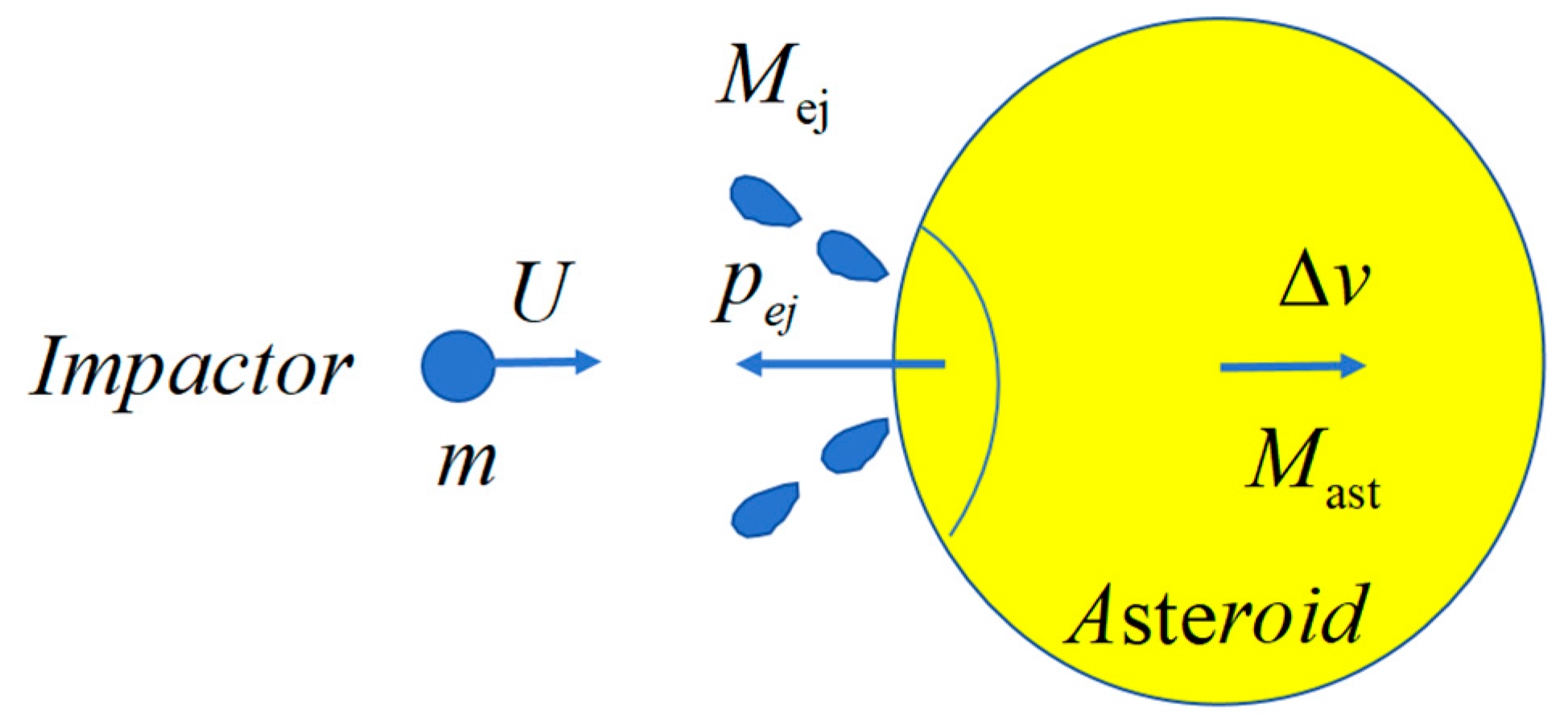
As shown in
Figure 1, the process of orbit disposal using impact can be divided into three stages: (1) the transfer of the impactor before the collision, (2) the disposal operations during the impact, and (3) the orbital deflection of the small celestial body after the impact. During the process of colliding with the target small celestial body, the impactor will transfer momentum with the small celestial body. At the same time, under high-speed impact, the material on the surface of the target small celestial body will be broken, producing impact ejecta, further enhancing the momentum transfer effect generated by the impact.
The conservation of momentum during the impact process can be expressed as follows:
Among them,
is the target mass,
is the momentum of the anti splash in the opposite direction of the projectile’s incidence, and
is the change in target velocity. Usually, the mass of the target is much greater than that of the projectile and splash, so the change in target mass before and after impact can be ignored. It can be seen that in order to obtain the change in target velocity after impact, in addition to direct measurement
methods, the key is to determine the momentum of the anti splash
or momentum transfer coefficient:
The larger the momentum transfer coefficient, the greater the momentum obtained by the asteroid, and the impact effect is about significant.
3. SPH Numerical Simulation Method
The SPH method is a numerical approach for solving partial differential equations and is a type of meshless method. This numerical method first discretizes the solution domain of the partial differential equation, then uses an approximate function to represent the field function and its derivative at any point, thereby transforming the partial differential equation into a series of discretized, time-dependent ordinary differential equations. Finally, these ordinary differential equations are solved using traditional numerical methods to obtain the numerical solution of the problem [
9,
19,
20].
3.1. Smooth Particle Hydrodynamics Approximation
The governing equations of continuum mechanics under no external force using Lagrangian descriptions include the following series of equations.
Conservation of mass equation:
Momentum conservation equation:
Energy conservation equation:
Here, denotes the spatial position vector, represents the velocity vector, is the total stress tensor, and superscripts and indicate the spatial coordinate directions. stands for density, represents internal energy, and denotes time. The SPH method is applied to discretize and approximate the fundamental conservation equations of continuum mechanics in the spatial domain.
The discrete form of the conservation of mass equation is as follows:
The discrete form of the momentum conservation equation is as follows:
The discrete form of the energy conservation equation is as follows:
Here, and represent the -th and -th particles, is the total number of particles in the tightly supported domain of particle , and represents the smooth function of particle affecting particle .
3.2. Artificial Viscosity and Equation of State
Artificial viscosity is commonly used in shock wave calculations to maintain the stability of SPH solutions. Currently, the most widely used is the Monaghan type artificial viscosity in SPH method, which not only converts kinetic energy into thermal energy, providing essential dissipation for shock wave surfaces, but also prevents non-physical penetration when particles approach each other.
The equation of state (EOS) is a formula that characterizes the relationship between pressure, density, and temperature within a fluid. During high-speed impact, the shear effect of materials under high pressure can be ignored, and solids will exhibit fluid properties. The response of materials can be described by thermodynamic parameters. Commonly used EOSs include linear polynomials, JWL(Jones–Wilkins–Lee), Gruneisen, etc. In addition, some material models, such as the Johnson–Holmquist Concrete (HJC) model, include material strength models, damage models, and EOS, where the EOS includes three stages: elastic compression, compaction deformation, and post compaction deformation.
4. Numerical Simulation of Impact Process
4.1. Simulation Process
The process of asteroid impact involves transient, large deformation, large strain, material failure, and even complete failure or complex contact structural problems [
21]. LS-DYNA has powerful analysis functions and rich material models, and has developed into one of the most famous universal multi physics field dynamics analysis software in the world, which can quickly solve multiple nonlinear contact collision problems.
When using the LS-DYNA solver for calculations, it is necessary to use both pre-processing software and post-processing software simultaneously. Commercial software such as ANSYS/ABAQUS or LS-DYNA’s built-in LS Prepost software can be used to define the modeling, meshing, and contact relationships of the model. After converting them into keyword files, the model materials, solution process control, output file format, and other key parameters can be set in LS Prepost (Version 4.3). Finally, the complete keyword file is submitted to the LS-DYNA solver (Version R11) for calculation. The result file is input into the post-processing software LS Prepost for analysis of stress, strain, velocity, overload, and displacement curves.
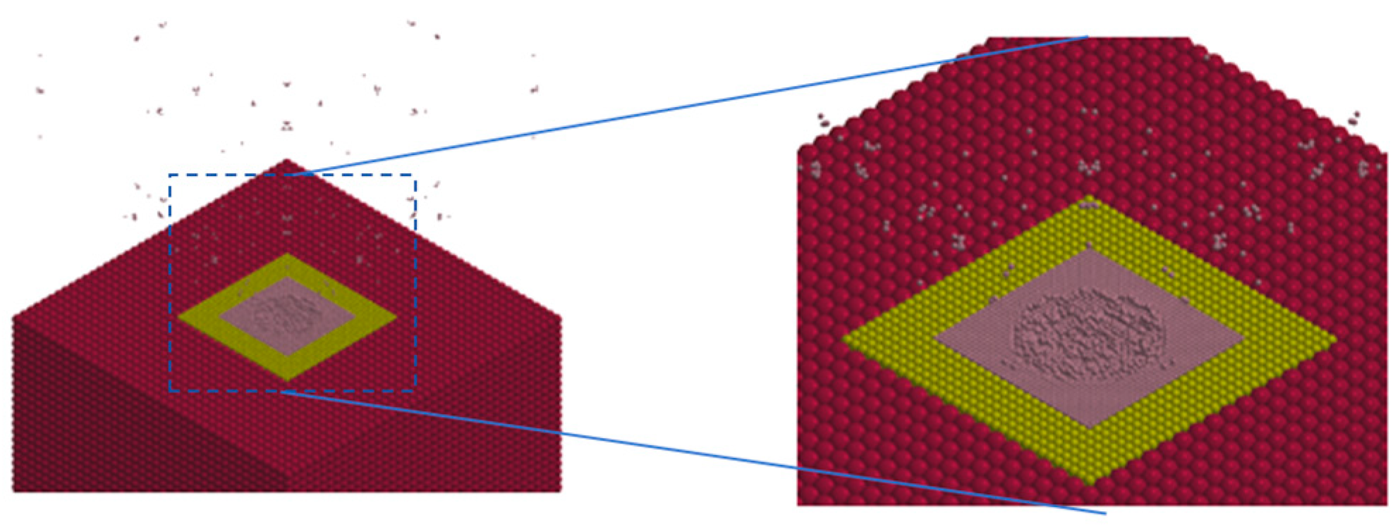
4.2. Simulation Model
The LS-DYNA finite element simulation software was used to establish a model of the flying disc impacting the target, as shown on the left side of
Figure 2. The flying disc is a polyester film cylinder with a size of 7 φ 12 × 0.3 mm, a density of 1.2 g/cm
3, and a total weight of approximately 0.041 g; the target is cubic granite with a size of 10 × 10 × 10 cm, a density of 2.85 g/cm
3, and a total mass of 2850 g. Both the flying disc and the target are simulated using SPH particles. To ensure calculation accuracy, the contact area between the flying disc and the target should maintain a similar particle density. At the same time, to reduce the computational workload, the particle density should not be too high. Therefore, the target is set to three layers, as shown on the right side of
Figure 2. The particles in the central area are the most dense, and they become sparser as they move outward. The number of target particles is 115,072, the number of flying particles is 52, and the total number of particles is 115,124.
The parameters in the LS-DYNA solver have no units. Users can unify the parameter units with the model size units based on the solving model. On the one hand, the impact penetration time of the seven hit device is extremely short, requiring only milliseconds to complete; on the other hand, choosing a smaller series time unit can indicate a larger 3-complex value, which is beneficial for step-by-step integration. Therefore, was chosen as the basic unit in the simulation.
4.3. Material Selection
In high-speed impact problems, it is necessary to consider the elastic–plastic relationship of materials under dynamic loads. Commonly used constitutive models for elastoplastic materials include ideal elastoplastic, bilinear elastoplastic, exponential hardening elastoplastic, and multilinear elastoplastic. Among them, the index hardening elastoplastic model (POWER_LAW-PLASTICITY) is a commonly used material constitutive model for plastic materials, which generates plastic hardening according to exponential observations after the material reaches its yield limit. The impactor adopts an exponential hardening elastoplastic constitutive model, which simulates the structural response of materials under high impact overload by setting strengthening coefficients, hardening indices, etc., as shown in
Table 1 [
22].
The Johnson–Holmquist Concrete (HJC) model was proposed in 1993 based on the Johnson–Cook model to describe the constitutive behavior and parameters of rock and soil [
23]. The equivalent strength of rock and soil is expressed as a function of pressure, strain rate, and damage, where pressure is expressed as a function of volumetric strain, and the effect of permanent crushing is considered. The HJC model considers the effects of strain rate, hydrostatic pressure, and damage accumulation on strength and is widely used in numerical calculations. Using HJC’s built-in failure criteria, FS < 0 is set to select the degree of damage, D, to control failure. On the other hand, due to the inadequacy of the HJC constitutive model in the static water zone, the minimum pressure at failure (MNPRES) = −7.4 × 10
−5 Mbar, the maximum principal strain at failure (MXEPS) = 0.35, and the maximum shear strain at failure (EPSSH) = 0.28 are added. The granite target material adopts the material parameters in
Table 2 [
22].
4.4. Impact Process
Consider the process of a flying disc colliding head on. At an impact velocity of 7 km/s, the impact process is shown in
Figure 3. Within a few milliseconds, the flying disc completes its contact and destruction with the asteroid, and the flying disc and target fragments are ejected outward. The target gains momentum from the flying disc and debris. Due to the small mass of the flying disc, it only creates shallow impact craters on the target surface.
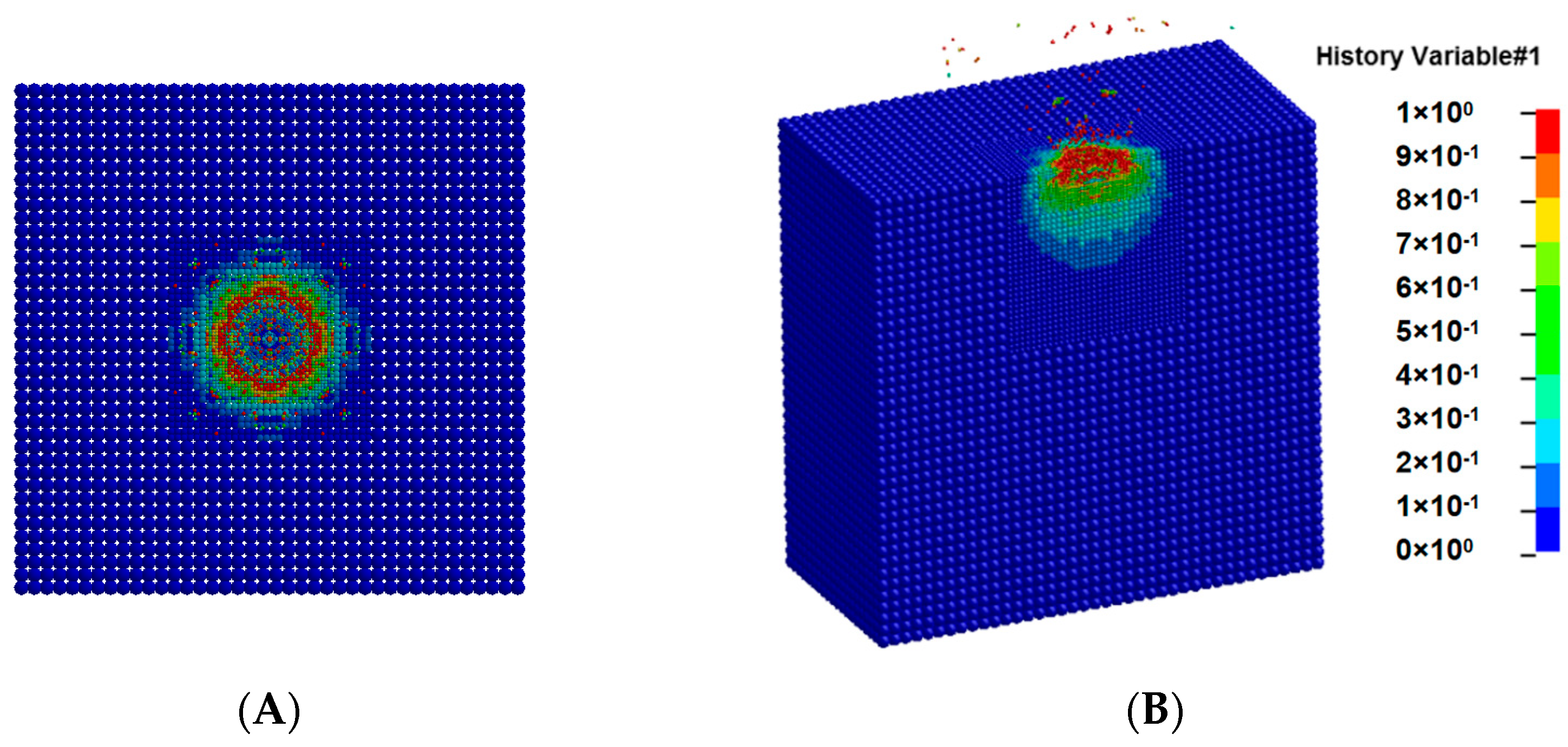
The damage distribution of the target during the impact process is shown in
Figure 4. After the flying disc hits the granite, shock waves appear inside the granite and damage occurs. Due to the small thickness of the flying disc, the backward shock wave inside the flying disc quickly reaches the rear surface of the flying disc after impact, resulting in unloading. After the unloading wave is transmitted to the granite target, the damaged material is ejected backwards. As time goes by, the damage and destruction inside the granite gradually stop, and the anti spray material gradually separates from the granite target. When the impact speed increases, the overall impact process is similar, but the intensity increases. Due to the frontal collision, it can be seen from the top view, as shown in
Figure 4A, that the damage generated by the target is a symmetrical circle. From the cross-sectional view, as shown in
Figure 4B, it can be seen that the damage generated inside the target is approximately semi-spherical.
4.5. Effects of Different Impact Speeds
In order to compare with the actual impact test, simulation analysis was conducted on the working conditions at different impact velocities such as 5 km/s, 7 km/s, 8.1 km/s, 8.9 km/s, 10.6 km/s, and 11.7 km/s. The velocity curve of the granite target is shown in
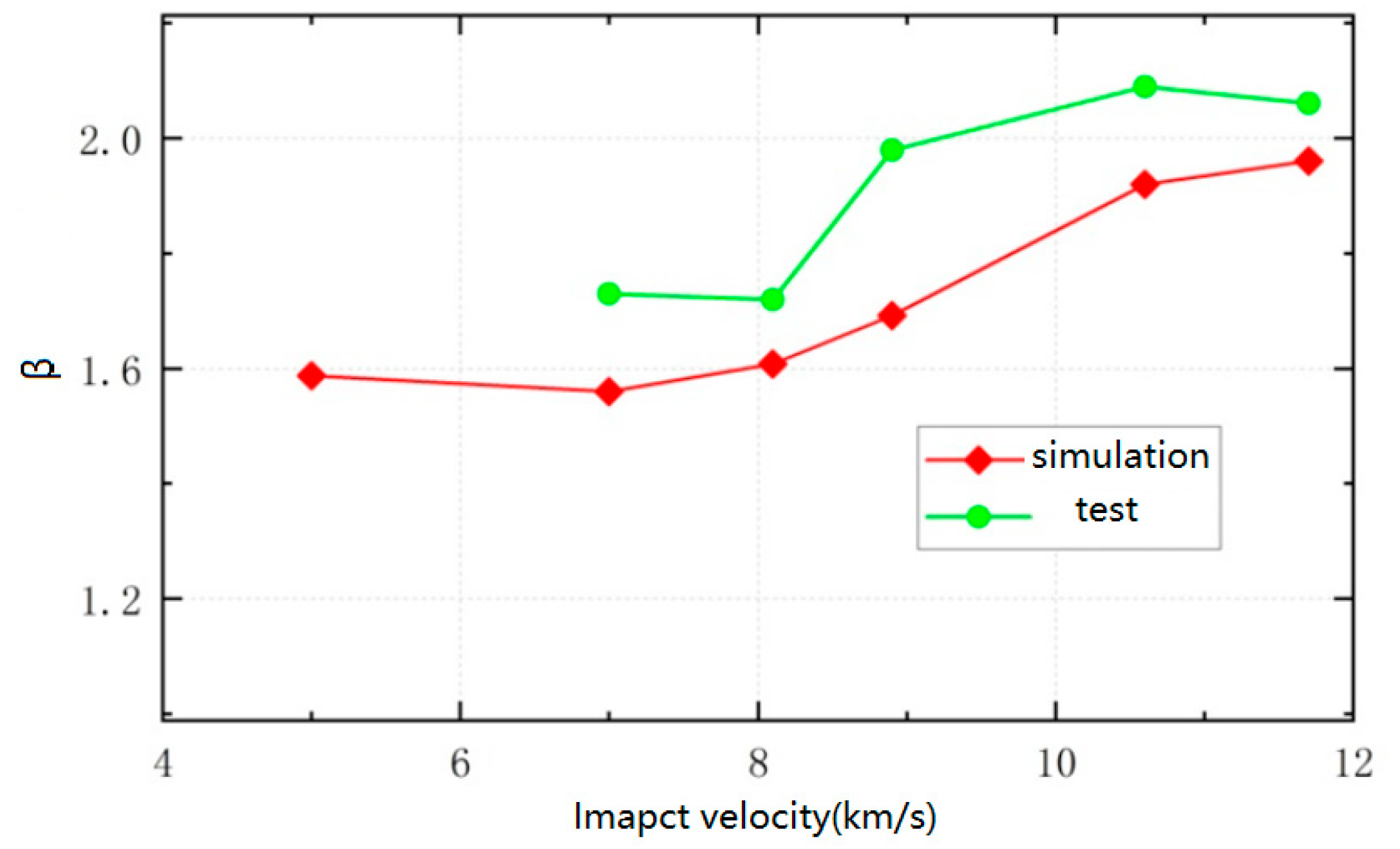
Figure 5. At different impact velocities, the movement trend of the target is basically consistent, reaching its maximum velocity at around 200 μs, followed by slight oscillations. After the impact ends, the elastic wave reflection inside the target gradually dissipates 1 ms later, and the granite target moves at the same velocity as a whole. The final velocity of the target is positively correlated with the impact velocity. When the impact velocity is 5 km/s, the target velocity is 0.117 m/s, and when the impact velocity is 11.7 km/s, the target velocity is 0.338 m/s.
Based on the velocity of the target after impact, the momentum obtained by the target can be calculated, divided by the momentum of the flying disc, to obtain the momentum transfer coefficient during the impact process. The momentum transfer coefficient increases with the increase in impact velocity, from 1.59 at 5 km/s to 1.96 at 11.7 km/s.
6. Conclusions
This article simulates the process of a flying disc impacting a granite target using LS-DYNA. The simulation shows that within a few milliseconds, the flying disc completes contact and destruction with the target, and the flying disc and target fragments are ejected outward. The target obtains momentum from the flying disc and projectile, which is consistent with the theoretical analysis results. The momentum transfer coefficient increases with the increase in impact velocity, from 1.59 at 5 km/s to 1.96 at 11.7 km/s. A ground high-speed impact system with a speed of over 10 km/s has been established, and the actual momentum transfer coefficient has increased from 1.73 at 7 km/s to around 2.06 at 11.7 km/s. The variation trend of the kinetic energy transfer coefficient obtained from experiments and simulations is consistent. Except for an error of 14.5% at 8.9 km/s, the error of other operating conditions is within 10%. The simulation process is effective and can basically reflect the actual impact process. Subsequently, the simulation parameters can be corrected based on the measured material parameters to further reduce simulation errors and provide a reference for the implementation of actual asteroid impact defense missions.
Although this study has achieved certain results in the kinetic energy simulation of asteroids, there is still room for improvement in the asteroid material and simulation condition design. In the future, we will further expand the types of asteroid materials and simulate the impact processes of more kinds of rocky and metallic asteroids to reveal the differences in their responses during impacts. Meanwhile, we will conduct refined simulations for various impact angles to analyze how angle variations affect energy transfer and destruction effects during impacts. Moreover, the optimization of impactor shapes will be a key focus of future research. By simulating different impactor shapes, we will explore their potential to enhance the deflection efficiency and impact effects on asteroids.


