1. Introduction
Typically, when acquiring indoor antenna measurements, spurious parasitically coupled scattered fields are largely attenuated by covering the interior of the chamber and much of the measurement apparatus with RF-absorbing material (RAM). This material is most often formed from open-cell, carbon-impregnated foam. While these types of absorbers are often considered to be broadband in nature, band limitations do exist, with these being largely governed by their electrical and physical size. The physical size is strongly coupled to their economic cost at the lower end of the spectrum and manufacturing precision at the higher end. This material cannot be perfectly matched to illuminating fields incident from all possible directions and polarizations, with the inevitable impedance mismatch resulting in some form of scattering. Furthermore, whilst considerable time, trouble, and ingenuity can be devoted to optimizing the placement of this absorbent material within the test range, it is not possible to install this on every surface, and generally, linear bearings, lights, fire detection and suppression equipment, etc., are often left exposed. This has become more of an issue in recent times with the rapidly increasing deployment of industrial multi-axis robots for test antenna and probe positioning. Here, the task is further complicated since absorber placement can serve to limit the final available range of motion, which is undesirable in a system that may routinely switch between several very different antenna acquisition modes. Thus, recourse to post-processing-based techniques to improve the quality of the antenna and scattering measurements becomes desirable in a wide range of test and measurement applications.
Although many scattering suppression methods have been proposed, with examples including time-gating (both hardware and software), spatial filtering, RF background subtraction, parametric repeat measurements, and waveform correlation, it is only during the past two decades that the use of mode orthogonalization and filtering-based post-processing techniques have become widely deployed in industry and academia to identify and subsequently extract measurement artifacts arising from parasitically coupled spurious scattered fields in antenna pattern and radar cross-section (RCS) measurements [
1,
2,
3,
4,
5,
6]. These have been used very successfully to greatly improve the facility-level uncertainty budget [
7] and have gradually become available for use with all commonly encountered forms of near- and far-field antenna range measurements.
These single-frequency mode-filtering-based approaches have been extended to admit the possibility of processing data that are sampled on irregular grids [
6] and, more recently, have been extended to take advantage of sparse sampling compressive sensing techniques [
8,
9]. Underpinning the success of each of these reflection suppression post-processing strategies and other modes of orthogonalization and filtering strategies is the behavior of the orthogonal vector wave (mode) expansions that are utilized to describe the radiated free fields and, in particular, their behavior under the isometric coordinate translations that are central to the success of the post-processing [
6]. Hitherto, all such translations have been implemented by first obtaining the true or quasi-far-fields. A differential phase change has then been applied to those fields to mathematically translate the test antenna back to the origin of the measurement coordinate system before those fields are re-expanded onto a convenient set of basis functions, i.e., modes, so that the mode filtering can be applied [
6]. Traditionally, the modal basis has been, respectively, either cylindrical or spherical, depending largely upon whether one- or two-dimensional data are being considered. However, the need to transform to the far-field to implement the translation of origins necessarily attenuates any evanescent fields present and, for the spherical near-field case, requires an additional spherical mode expansion and a further additional spherical mode summation that in principle is unnecessary if instead the translation of origins operation were performed
directly upon the spherical mode coefficients (SMC) by instead harnessing a generalized vector addition theorem for the isometric antenna position translation.
Standard spherical near-field theory is based on the transmission equation derived by Jensen and Wacker [
10,
11], where the AUT and the probe are described by spherical mode coefficients that are the complex coefficients of basis functions that are themselves elementary solutions to Maxwell’s equations in a spherical coordinate system. In principle, the transmission equation is valid for any arbitrary test antenna and probe combination at any orientation and separated by a distance between the spherical coordinate system origin and the probe that is larger than the minimum sphere radius,
ρ0, that will completely enclose the majority of the test antenna current sources [
6]. This transmission formula can be inverted using the rotation group orthogonality theorem and then solved for the probe-corrected AUT transmit coefficients using the Kerns transmission formula [
12]. Thus, the electric and/or magnetic fields transmitted by the test antenna in this region of space, which is also assumed to be source-free, linear, isotropic, and homogeneous, can be expressed as the linear superposition, i.e., the complex weighted sum, of spherical waves through the spherical wave summation. And, as with any form of modal expansion that is predicated on Maxwell’s equations, which, in turn, require the modal expansion region of space to be source-free, linear, isotropic, and homogeneous, there are no additional sensitivities here. Thus, so long as the normal precautions of absorber placement used in near-field measurements are followed, the method can be applied. Spherical mode coefficients (SMC) are complex numbers that are functions of frequency—the polarization index is
s, the polar index is
n, and the azimuthal index is
m, such that 0 ≤
n ≤ ∞ and −
n ≤
m ≤
n—which do not vary with any of the spherical scanning coordinates. The summation can, in practice, not be infinite, and instead, the maximum value for the polar summation is generally truncated to a finite positive integer number, which is large enough to enable the field to be represented precisely and accurately. Thus, it is assumed that the antenna under test (AUT) is enclosed within a sphere of radius ρ
0 such that spherical waves of integer order
N >
k0ρ
0, which, when taken together with an additional positive integer safety factor that depends upon the desired accuracy, represent the most complicated field structure that can be generated by the given radiator. Thus, once obtained, this finite, large set of complex coefficients can be used to accurately and very efficiently represent the radiative properties of the AUT. This makes any post-processing that acts rigorously and directly upon this set a very attractive proposition. This is precisely the approach taken by the present work. However, it is not the intent of this paper to revalidate the mode-filtering technique, as there is already a huge body of literature devoted to that cause, including many of the references included within this text and especially [
6]. Instead, this paper concentrates on developing an alternative way of laying out the requisite computation that is more general than that which has come before, and it is shown to reduce to an exact numerical equivalent in the absence of evanescent fields.
The structure of the remainder of this paper is as follows.
Section 2 presents a summary of the computation required by the translation of the spherical wave formula, before
Section 3 presents a verification of the translation through numerical simulation.
Section 4 presents an overview of the simulated experimental setup before
Section 5 presents the results of the new frequency-domain spherical mode-filtering reflection suppression technique. This paper finishes with
Section 6, which presents a discussion of the primary results, and provides a summary of the conclusions and the planned future work.
2. Translation of Spherical Waves
Let us consider two conventional right-handed coordinate systems. We may assume that these are initially coincident and synonymous. We then assume that the first, unprimed system is fixed in space with the primed system being displaced by a distance
A in the direction specified by the conventional right-handed polar spherical angles
,
. It can then be shown that the translation of spherical waves can be expressed, when using the shorthand formulation of [
13], as a linear operation [
14] so that the spherical wave function
can be expressed as a combination of spherical waves defined in the primed system
:
Here,
are a set of spherical vector wave functions inside the primed coordinate system, with
indicating the spherical radial function assuming the usual 1, 2, 3, and 4 numbering system introduced in [
15]. Thus, we use
c = 3 for the spherical vector wave functions before
and then after
in the unprimed coordinate system once the translation operation has been applied, matching the outward traveling wave assumption from [
16]. This is a very general statement, as it can be shown that this is equally valid for inward traveling waves for which (
c) = 4. In this case, we use (
c) = 1, i.e., Bessel functions of the first kind within the calculation of
, so that this translation can be applied to incoming
or outgoing waves.
It is noted here that the above translation expressed by Equation (1) is a generalization of the far-field differential phase change operation described above, which is fundamentally a
different operation from the translation required for spherical near-field measurements, where both far-field phase
and amplitude are affected [
6]. While it is common to see in the open literature, e.g., [
13,
16], both translations being differentiated by explicit limitations in the form
or
, in
Appendix A, for the present work, it will be shown that there are no such limitations here except possibly those imposed by the particular application. This means that Equation (1) is valid for large magnitudes of
A so long as it is understood that the minimum radial extent of the translated antenna also increases with
r +
A, and thus, the translation matrix needs to be extended accordingly to ensure sufficiently higher-order modes are available to properly represent the antenna. Similarly, the limitation of
stems from the requirement to properly decouple the translated modes of a probe from those of the modes of the antenna under test (AUT) in a spherical near-field (SNF) measurement configuration. To better understand the difference between these cases,
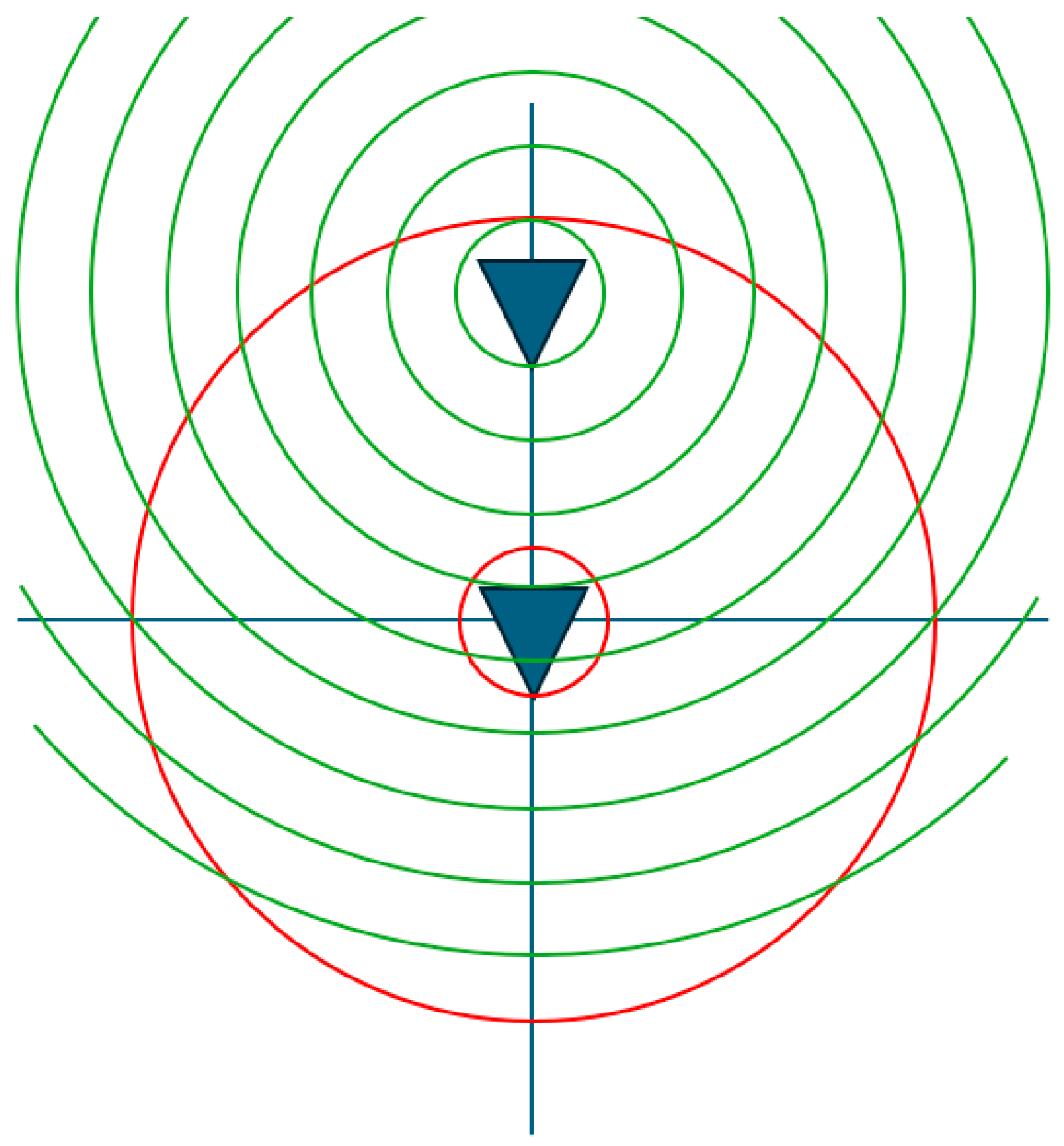
Figure 1 shows the translation presented in this paper where only the corresponding far-field phase distribution of the antenna pattern is affected, which is congruent to a multiplication with
of the far-field pattern. The minimum radial extent of the antenna increases together with its offset, as indicated by the red circles. It is noted here that the translation displaces the origin of the mode spectrum; this means that to move the AUT forward in the
z-direction, one actually has to shift the origin of the spherical wave functions in the negative
z-direction. Conversely, in
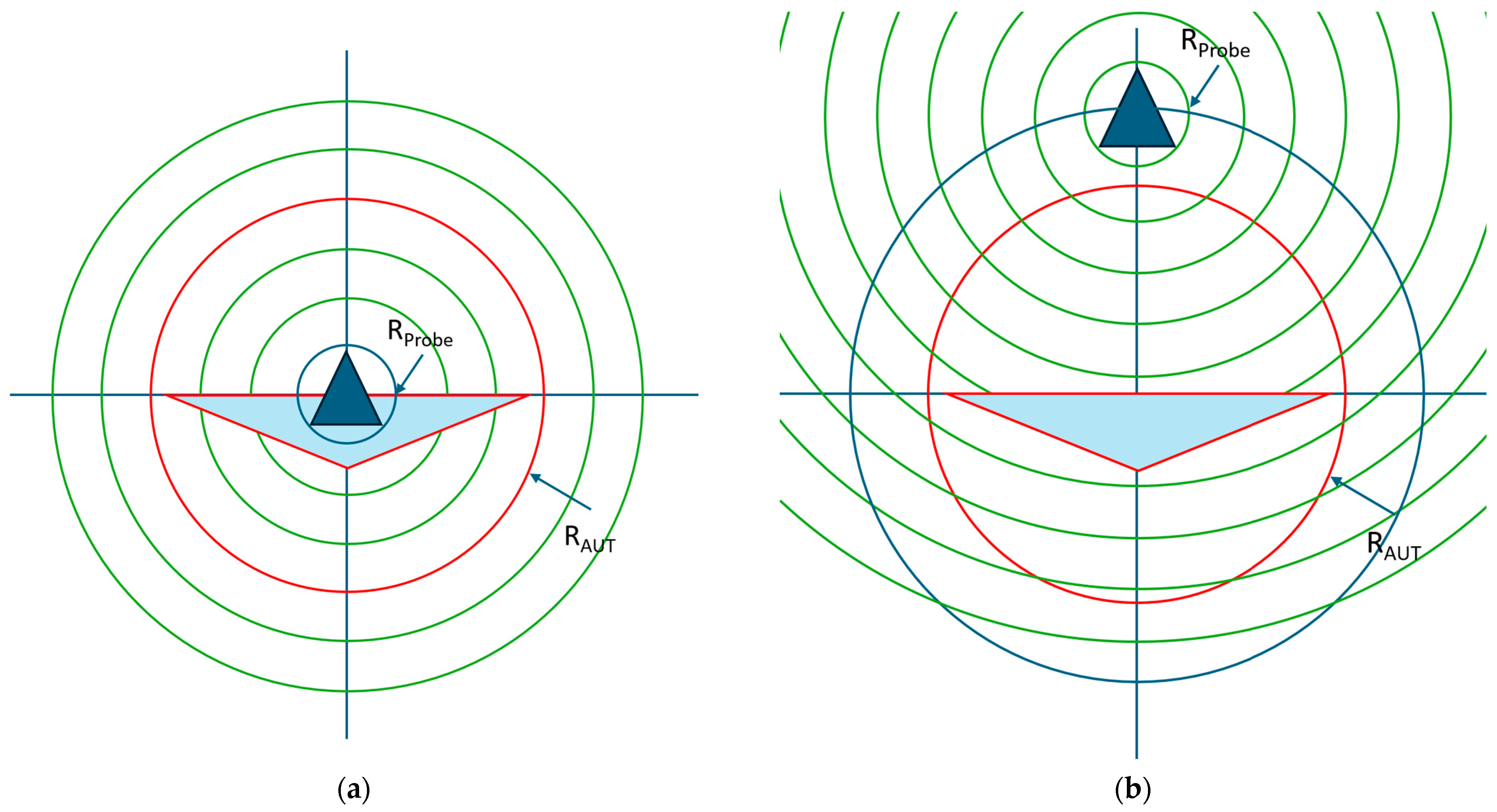
Figure 2, the translation is
outside the minimum radial extent of the antenna, which affects both the corresponding far-field amplitude and phase distributions. Here,
Figure 2 is divided to illustrate both the untranslated and translated cases, showing its application for the special case of spherical near-field antenna measurements, where the AUT
and the AUT radial extent remain located at the origin of the measurement coordinate system, and the probe is translated outside of the AUT radial extent. The corresponding far-field amplitude distribution of the translated antenna with increasing distance gradually narrows down until, in the limit, it becomes a single angular point on the pattern. Thus, in the limit, this corresponds to a plane wave coupling between the two spheres, thereby transitioning from a near-field to a direct far-field measurement, meaning that at certain distances the probe angular pattern essentially becomes negligible, and the compensation procedure essentially reduces to just a polarization correction.
The translation coefficients are defined as [
14] and can further be expressed as
where
is a normalization correction factor, which is dependent upon the chosen normalization of the spherical wave expansion (SWE), and
is the Dirac delta function [
6]. Several conversions between different normalizations are reported within the open literature, with a summary being presented within (A1) of [
15]. For the present work, however, the translation coefficients
and
are based on the spherical wave functions described by Edmonds in A1-11 of [
15], while the SWE utilized to attain the spherical mode coefficients employs the normalization proposed in [
13,
16]. Thus, the requisite correction factor for the normalization employed here can be expressed as
with
and
for which
Here,
’s are the linearization coefficients, which can be expressed in terms of Wigner 3-j symbols [
15], and
is the spherical radial function of order
p and type
. Furthermore,
denotes the associated Legendre function of degree
p and order (
. However, given the number of factorials required, these turn out to be enormously computationally expensive to calculate directly. Fortunately, an alternative strategy may be harnessed involving the computation of these coefficients by means of efficient, stable recurrence relations [
14]. Recurrence relations greatly reduce the computational complexity of calculating the coefficients, with this becoming increasingly important as the number of coefficients increases. This is especially crucial as the highest-order coefficient depends upon the frequency, minimum sphere radius, and the size of the translation. Once the scalar coefficients have been obtained, these can then be used to derive the vector addition coefficients. When taking this approach, the addition coefficients can be written as follows:
and
Here, Equations (7) and (8) refer to the calculation of the scalar translation matrix, which is in the form of
, for which recurrence relations also exist and are developed in [
17]. Here, the starting values for
n = 0,
m = 0, i.e.,
can be easily derived from the scalar wave equation using
Here,
is the spherical radial function of order
n and type
.
where
is the associated Legendre function. This calculation also makes use of the standard relation
[
17]. Then,
may be expanded using the relation
where
and
The recurrence relation for
is derived from the
values, where the starting points are
m =
n so that the requisite recurrence relations are
where
and
Lastly,
is derived from
using
Thus, using Equation (1), a translation can be applied in any direction and in either sense, where the displacement is defined as , and where the magnitude of the displacement |r| can be larger or smaller than the minimum sphere radius.
The memory consumption of the final translation matrix depends on the number of input and output modes considered. If the AUT at the input is displaced, the occupied MRE is expected to be larger than the AUT itself, which, after translation back to the origin, is reduced. The size of the translation matrix can be written as follows, assuming for each point P a double-precision complex number:
with
where
is the MRE, and
is the wavelength.
For the pre-calculation of
, however, a matrix of the following size is required as well, which is about half the size of the translation matrix:
In principle, there is no practical numerical limitation to the maximum number of
N-modes that can be used with the recursive formulations to determine the translation matrix. However, the direct calculation of the Legendre polynomials currently utilized has a higher-order limit of approximately
N = 85, although when required, this can be easily extended using the Symbolic Math Toolbox or by adopting alternative recursion formulae that are available in the open literature [
15].
3. Verification of the Translation of Origin Formula
In order to verify the translation algorithm, a standard gain horn (SGH) pattern has been simulated using its amplitude and phase distributions sampled across a small surface distributed on the
xy-plane at
z = 0, from which, using the Kirchhoff–Huygens formula [
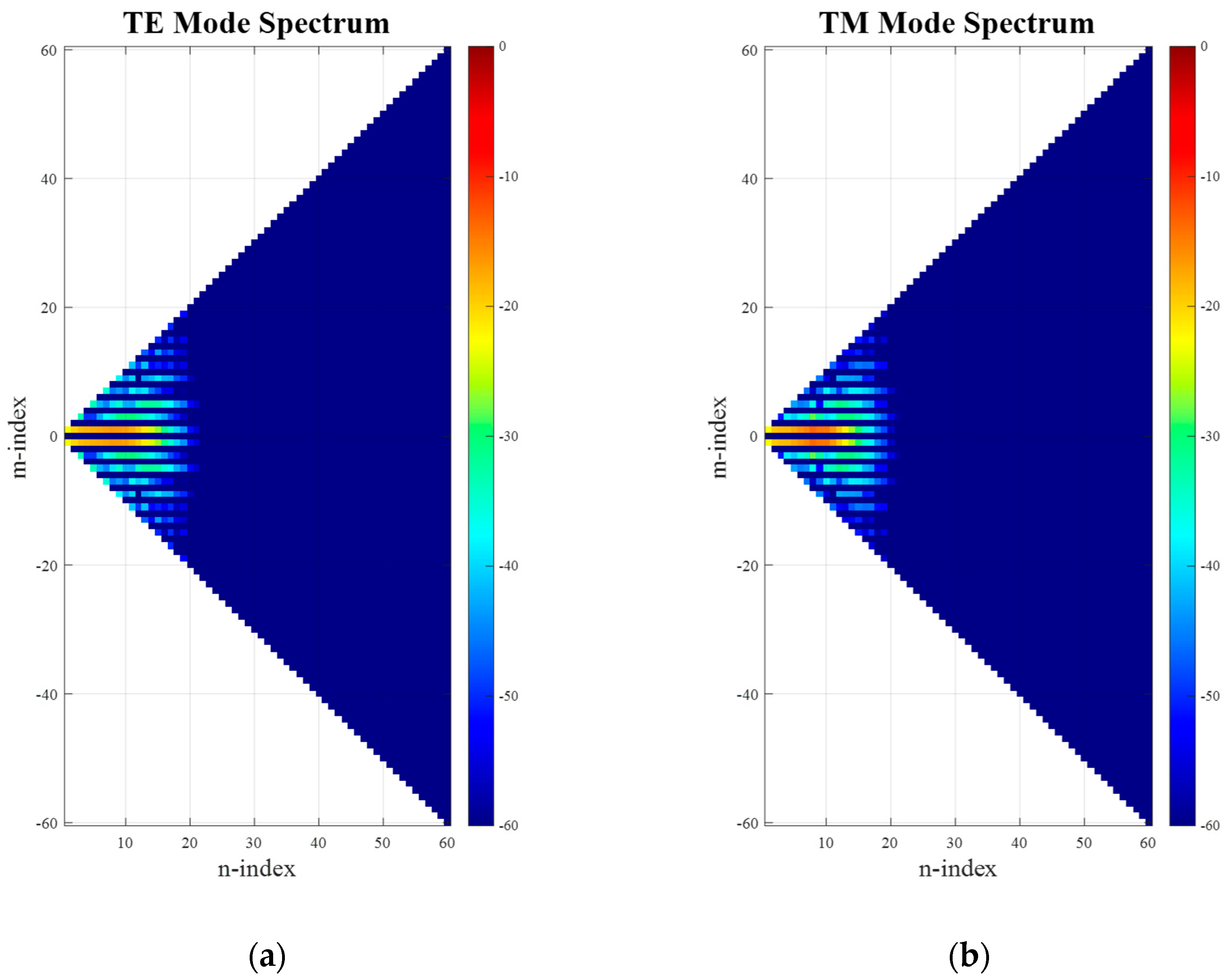
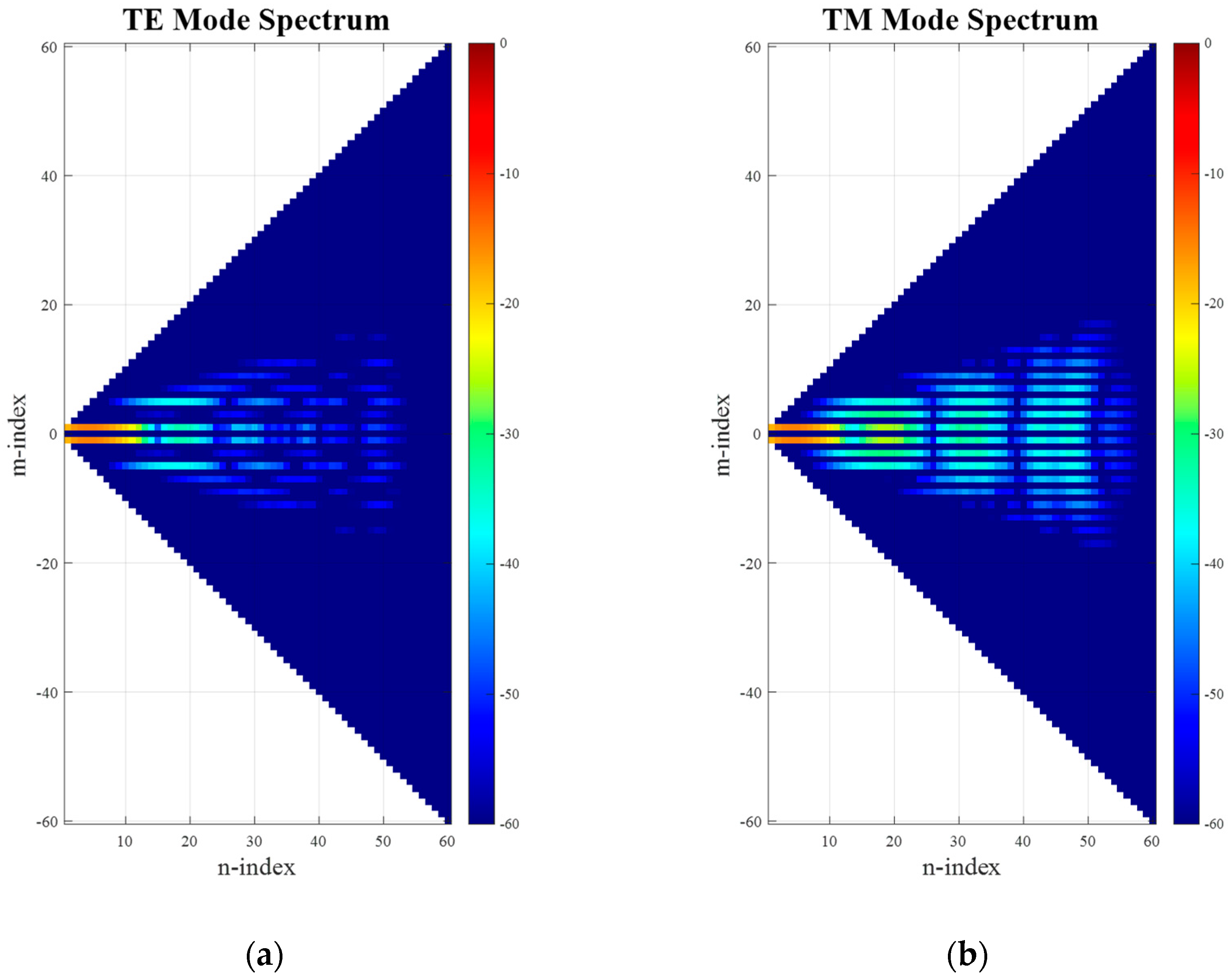
6], the full far-fields may be determined. In so doing, it is understood that the resulting far-field pattern origin is not coincident and synonymous with the antenna pattern phase center. This is not a restriction for the purpose of the following verification. The far electric fields can then be expanded onto a set of spherical modes to yield the spherical mode spectrum shown in
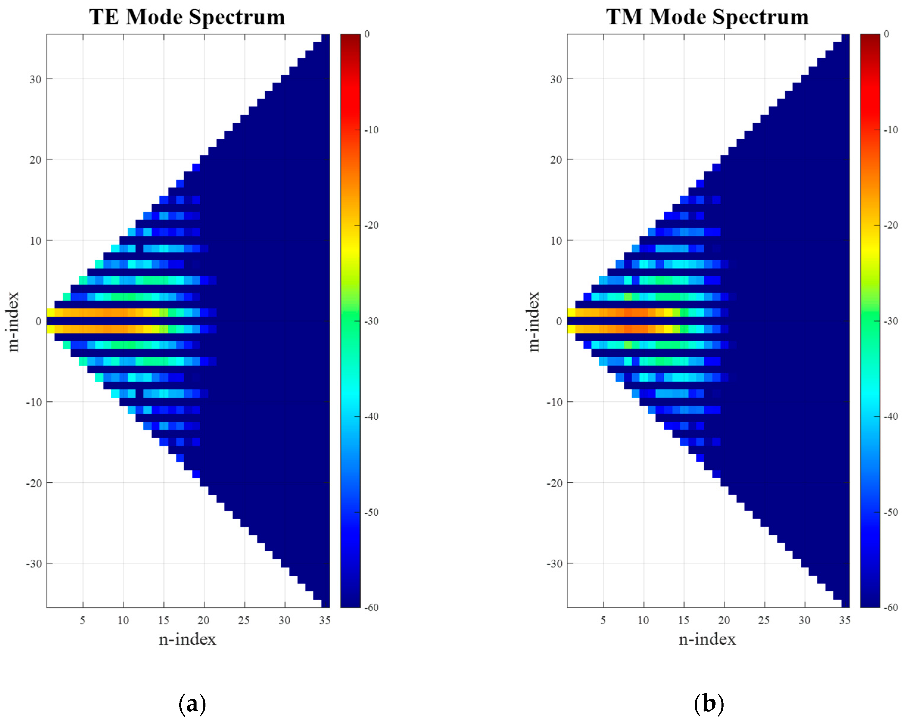
Figure 3. Here, it can be clearly seen that the minimum radial extent is limited such that the lowest
circa 25 modes contain the majority of the power radiated by the antenna and should be sufficient to describe the antenna far-field pattern, as in this case of
nmax =
k0a + 10 = 25, where 10 is a typical empirical factor that is usually added for problems of this electrical size and which depends upon the desired accuracy, cf. [
6,
16], especially [
18]. Next, we apply a translation to the AUT in the z-axis using the conventional approach of adjusting the far-field phase function. Thus, as a second step, on the far-field pattern, a phase-shift is applied, which is a function of the polar pattern angle
, the free-space propagation constant
k0, and the displacement distance
Offset. This phase shift represents the physical movement of the antenna in the
z-direction away from its phase center and measurement origin. This can therefore be expressed as
where
is the far-field measurement of the SGH when at the origin, and
is the representation of the measurement with the offset applied.
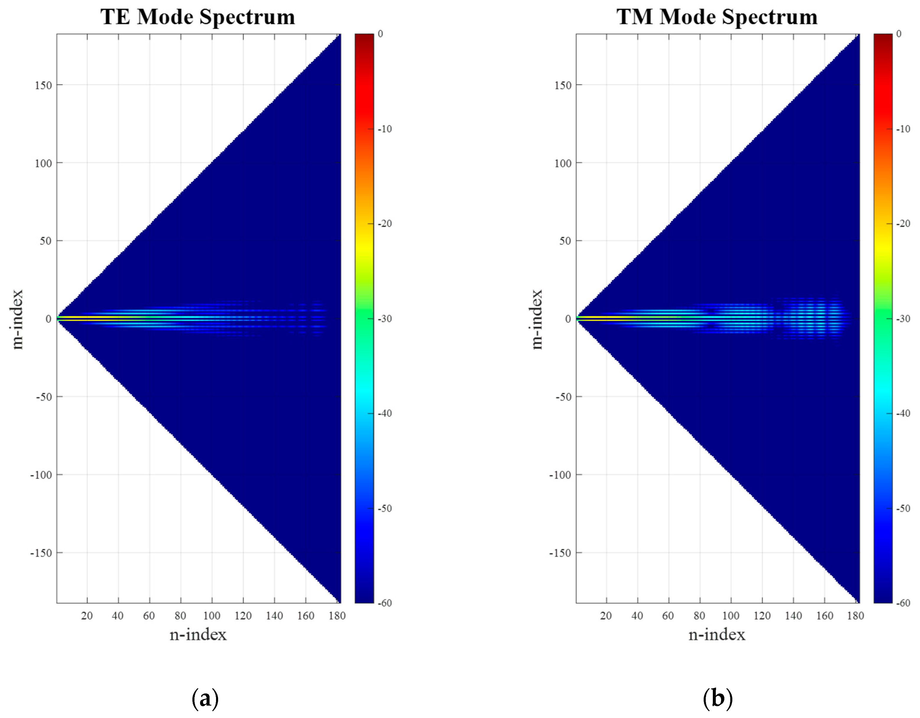
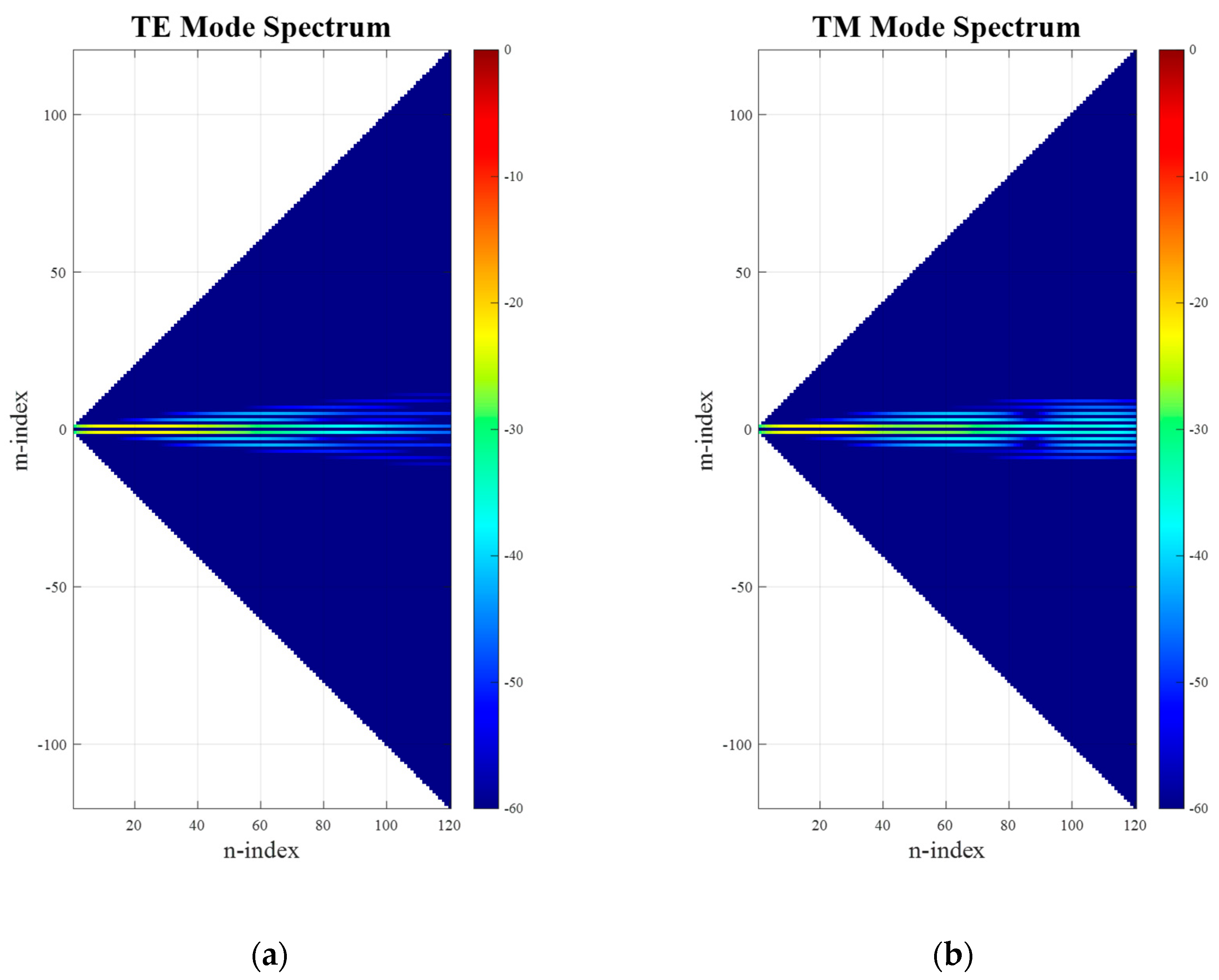
After applying an SWE to the far-field pattern of the translated antenna (including the phase shift), the resulting spherical mode distribution can be seen in
Figure 4. While comparing
Figure 3 and
Figure 4, it is clear that the occupied mode space in
N can be seen to have significantly increased, extending up to the full calculated space of 60 modes. This is expected, as now
nmax =
k0(
a +
Offset) + 10 = 60. However, due to the purely
z-directed translation direction, the pattern symmetry is not broken, and thus the distribution width in
M-direction has been preserved.
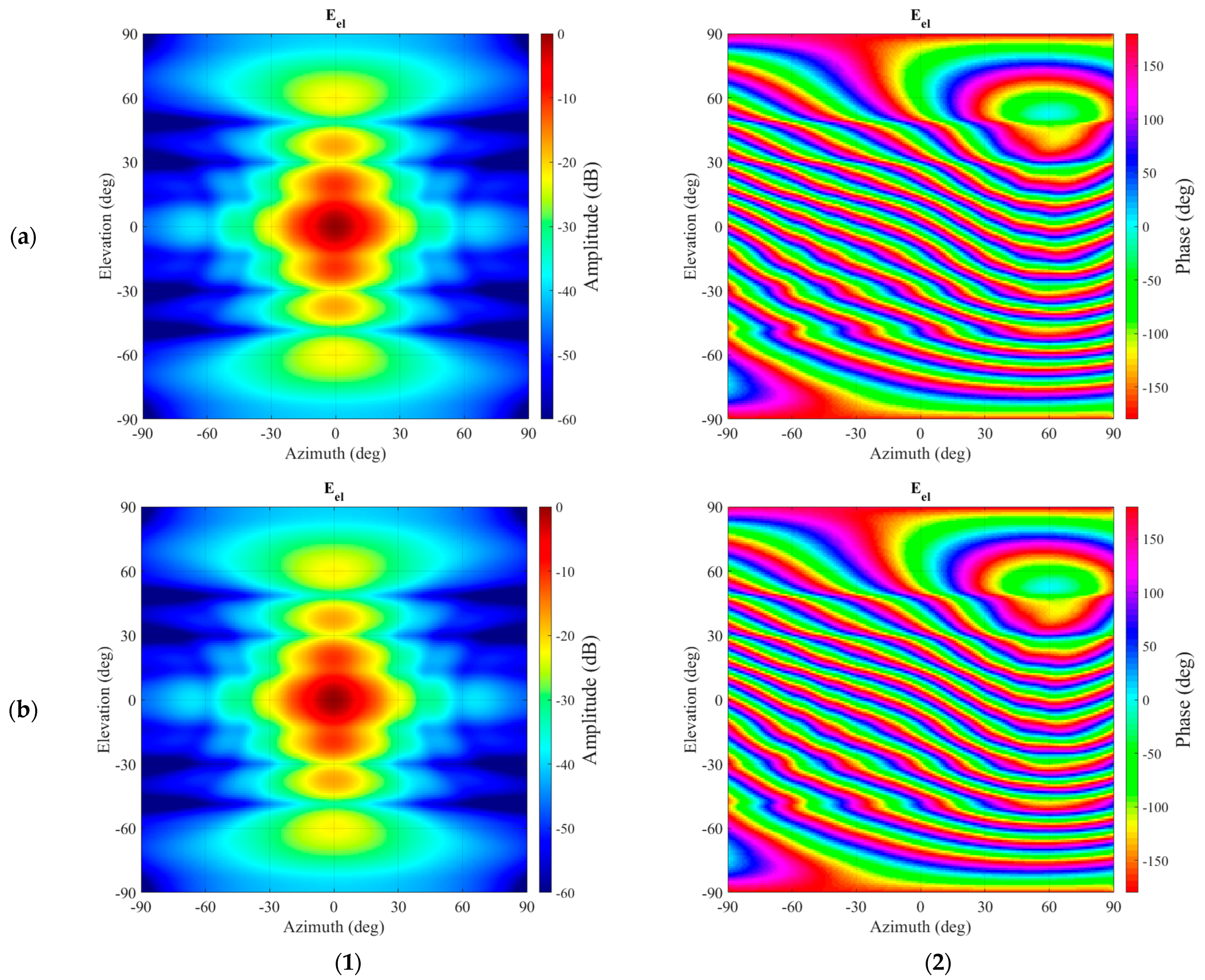
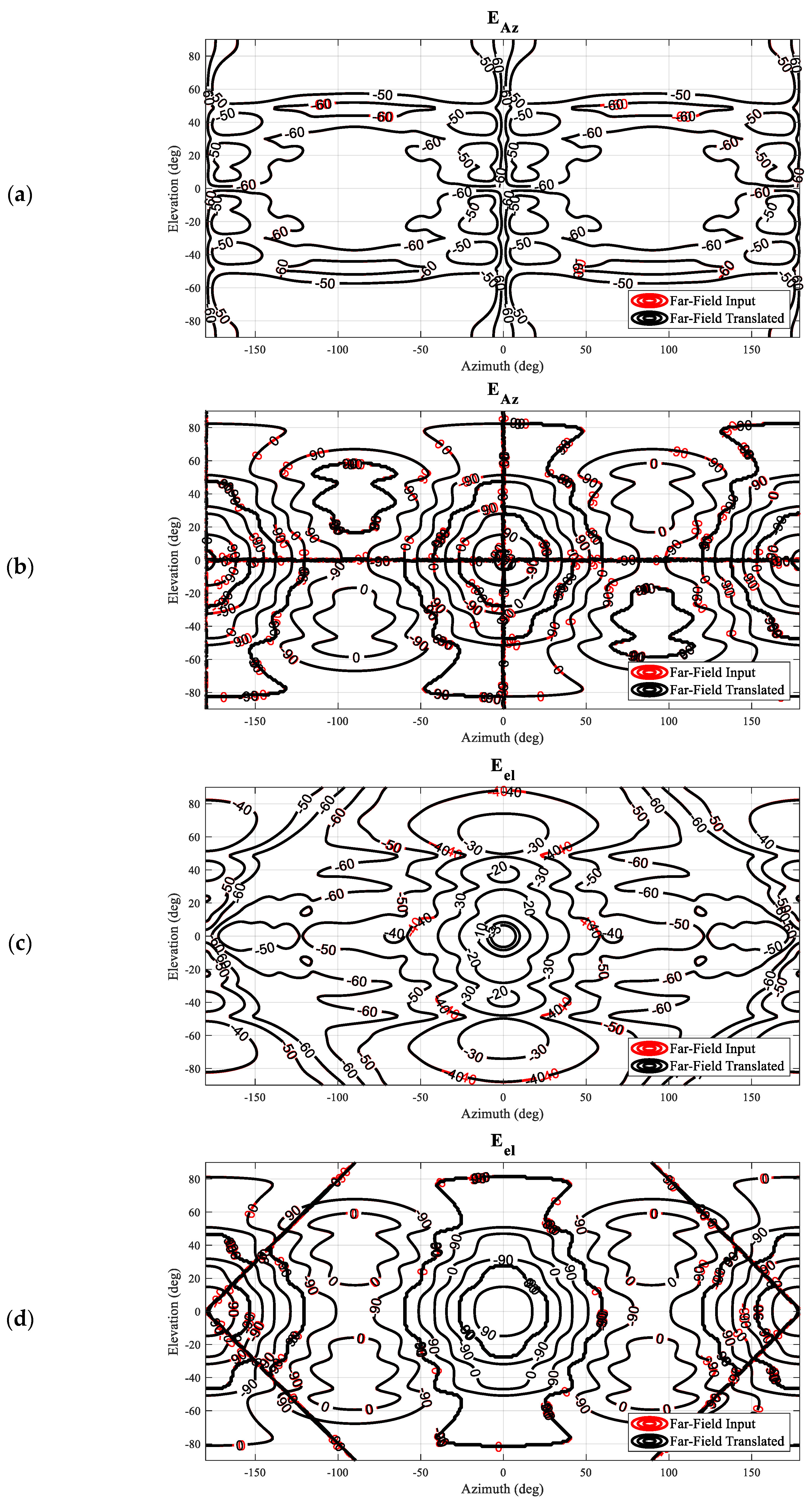
Next, we may translate the antenna back to its original position by utilizing the vector addition theorem presented above to implement an equivalent translation directly upon the SMCs. In the case that the mode translation operation works correctly for this case, the resulting far-field amplitude and phase patterns should agree exactly with the initial starting data. In
Figure 5, comparison contour plots of the simulated antenna (input) and the back-translated patterns are shown tabulated on a regular azimuth-over-elevation grid, denoted by red and black contours, respectively. Here, it can be seen that for both field components, the amplitude patterns (a) and (c) are nearly indistinguishable from one another. The phase distribution of the elevation field component, which represents the co-polar pattern, is found to have an excellent match as well, while the cross-polar azimuth field component shows a little larger difference between the input and the translated data. One has, however, to keep in mind that the respective amplitudes are more than 50 dB below the pattern peak, and most likely the differences are caused by the higher-order mode cut-off of the mode spectrum of the shifted pattern, as well as numerical truncation and rounding, rather than due to the translation operation itself. That being said, the co-polar and cross-polar amplitude and phase patterns are all in such good agreement that each of the contours overlays precisely, with even the positions of the contour labels coinciding, which is a very encouraging result indeed.
Based on the performed comparisons shown in
Figure 5, it can be concluded that the translation of origin described can be used as an alternative to the far-field pattern-based displacement operation, which multiplies the far-field antenna pattern function with a complex exponential,
, and filters out any evanescent fields. And, as has been verified previously, cf. [
19], the mode translation can be applied in any direction and not merely along the
z-axis.
Appendix B below contains a further example of the verification of a general translation that was specifically
not aligned with the
z-axis.
4. Experimental Setup of the Mode Filtering
To further validate the application of the generalized vector addition theorem to the mode-filtering-based reflection suppression, a numerical model has been created using the proprietary full-wave three-dimensional computational electromagnetic solver Altair Feko [
20]. To make the simulation sufficiently realistic, a model of a 48-element planar array antenna was simulated and used as an AUT [
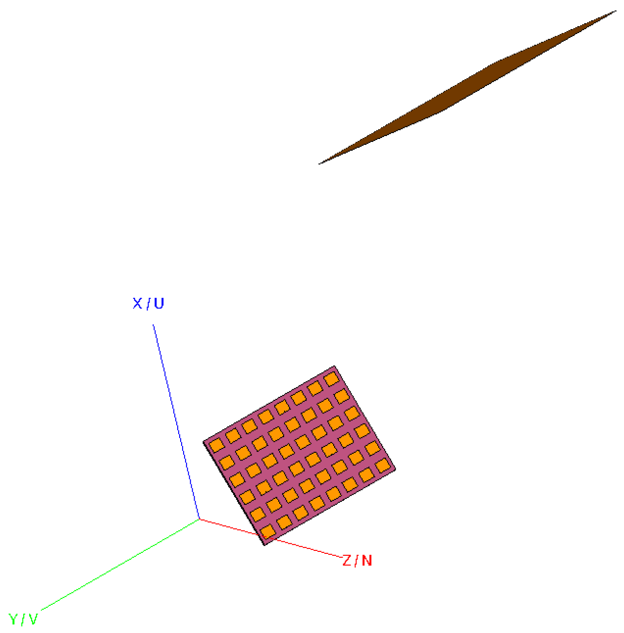
21]. The spherical near-field measured pattern of the AUT was then perturbed with the inclusion of a perfect electric conducting (PEC) square plate, which was included to create the requisite complex environment and provide the parasitically coupled scatterer.
Figure 6 shows the experimental configuration in the modeling software. By stepping the orientations of the model of the AUT through a sequence of rotations, a measurement using a traditional “roll-over-azimuth” positioning system [
6] was simulated.
Figure 6 shows a randomly chosen example where the AUT has been rotated to the virtual measurement angle of
. In this particular simulation, the AUT was located displaced by 360 mm from the origin of the simulated spherical “measurement” setup, in
z-direction of the AUT coordinate system. On the top-right-hand side, a large PEC scatterer can be seen. Here, the center of the reflecting plate is positioned 1000 mm above and right from the global coordinate system origin and oriented at approximately
to the
yz-plane, which results in a maximum effect in disturbing the far-field pattern of the AUT. It is further emphasized that the location and orientation of the plate remain statically located with respect to the global coordinate system, which mirrors the practical case of a scatterer that is located at a fixed position within the test chamber. The amplitude and phase distribution of the AUT was previously described in reference [
21]. While the excitation is not especially important for the present work, the general complex nature of the field distribution makes it far more attractive than a simple analytical field such as that used above to confirm the validity and applicability of the translation algorithm itself.
When constructing a measurement simulation such as that needed here, one has to keep in mind that whilst the simulation software does allow the user to sample the radiated field from some given radiating structure in three-dimensional space quite easily. In the present case, where the AUT has to be rotated through a full range of
orientations of the virtual “model-tower” spherical positioning system [
6], the scatterer has to retain its position and orientation relative to the sampling near-field probing point. Thus, for each unique spherical near-field position, the model must be simulated separately, after which each time a single near- or far-field point of the model can be sampled in the range “boresight” direction at θ = 0°, φ = 0° in the global coordinate system. Thus, when using a 3° angular data point spacing in both θ and φ directions, which is required by the spherical sampling theorem for this size problem and test frequency, this leads to a total of 7320 points to be “measured”, i.e., 7320 individual, full-wave method-of-moment (MoM) simulations. Although there are a great many different computational electromagnetic (CEM) simulation methods that could have been harnessed for the purpose of constructing this simulation, MoM was chosen as it encapsulates all of the complex scattering properties of this problem, which avoids the need to mesh large regions of vacuum, which would have otherwise greatly increased the problem size and made this already large and computationally expensive simulation significantly more challenging.
5. Application of the Generalized Vector Addition Theorem in Mode Filtering
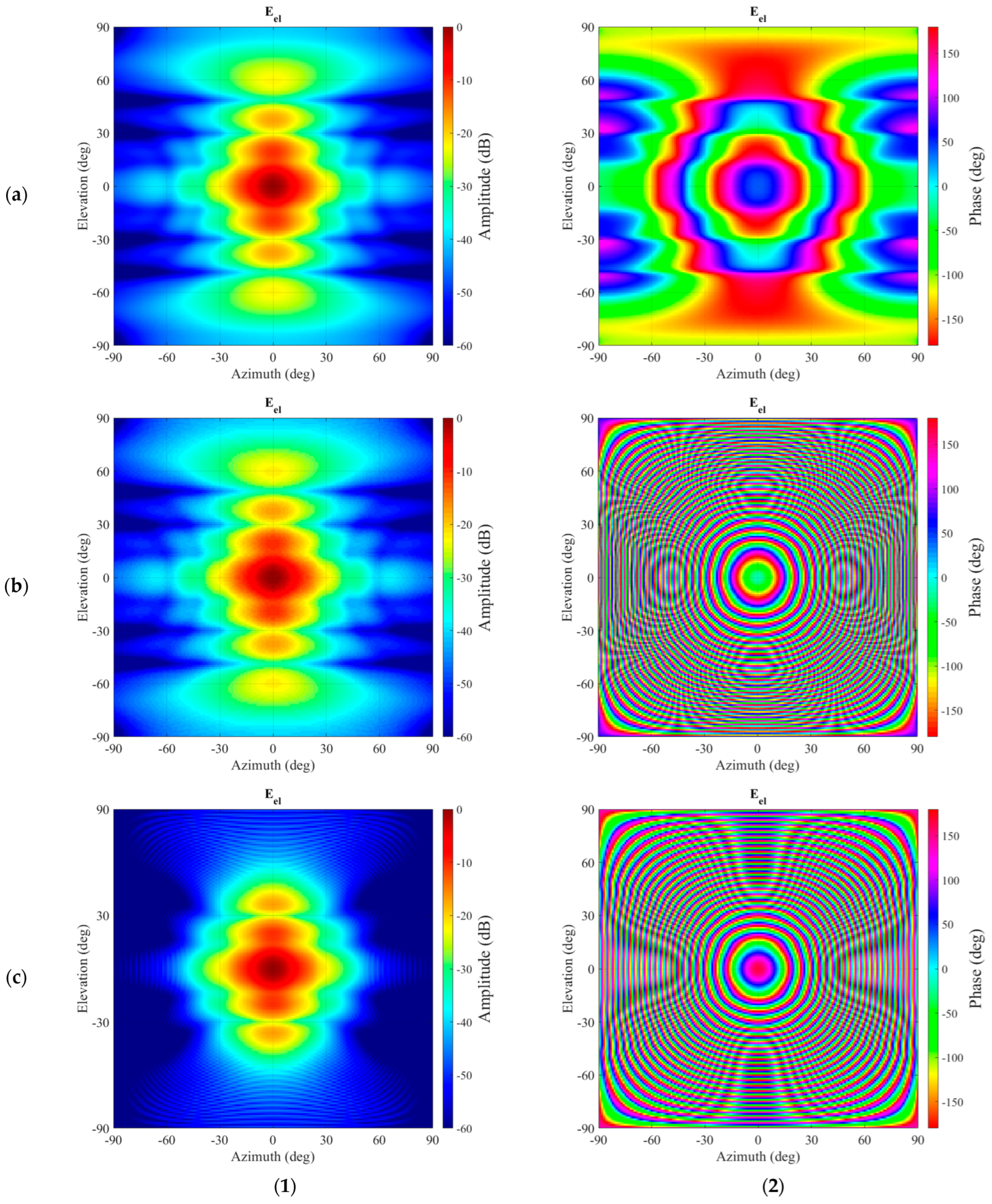
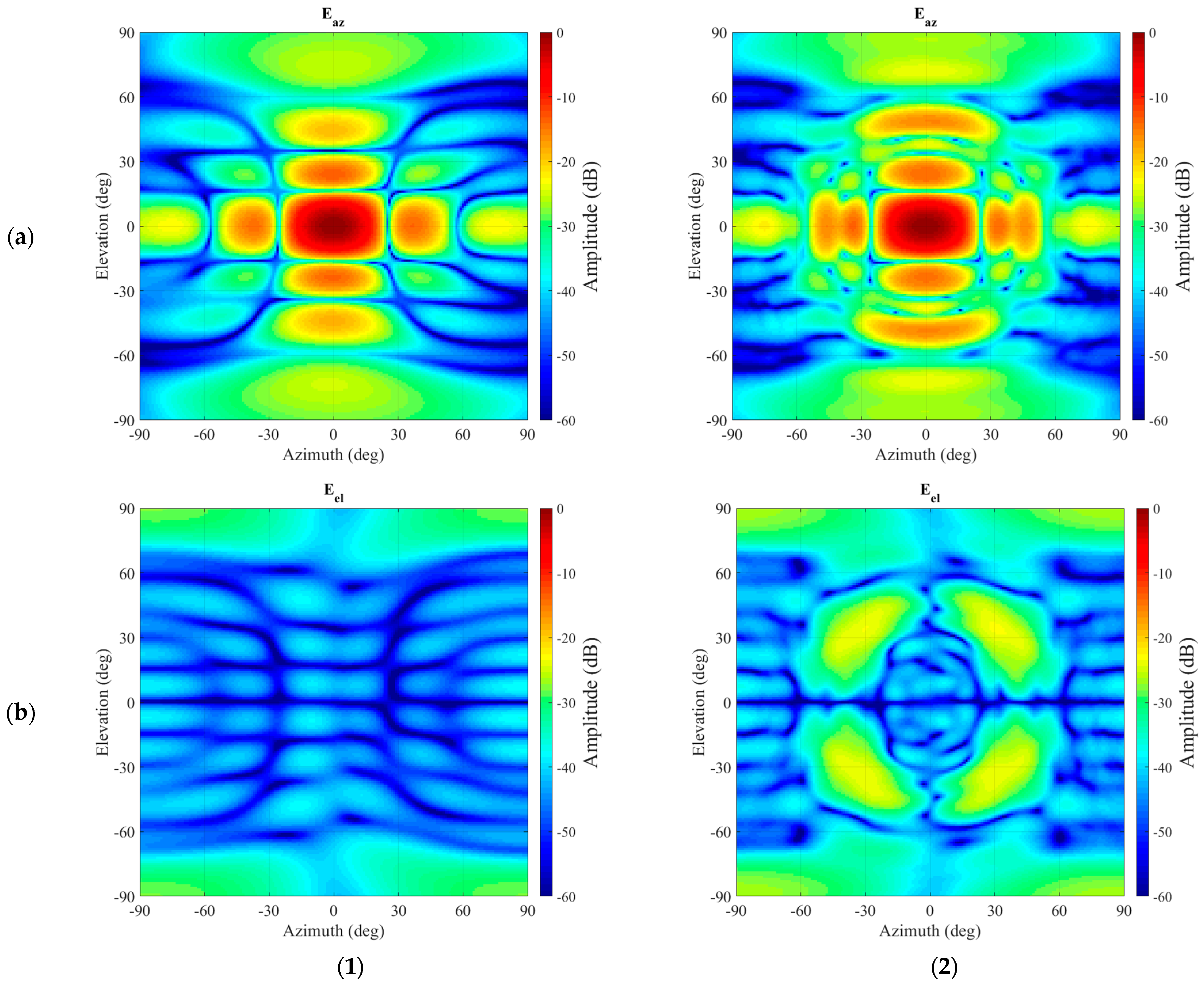
The full-wave CEM simulation described above was then used to provide the data needed to carefully verify the new processing algorithm. Thus, for the present case, a spherical near-field measurement was simulated with a measurement radius of 2.0 m. As a reference, a second set of simulated “measured” spherical near-field data was attained without having the scatterer present. This is a conventional simulation that can be obtained using a simple model of the test antenna in isolation. Both SNF data sets were then processed using a standard spherical near-field to far-field transformation (SNFFFT) [
6]. This allows the effect that the scatter has on the far-field pattern of the particular AUT to be clearly seen. Given the large electrical size of the scatterer, the effect on the pattern is intended to be significant, and this can be clearly seen by examining the contour plots of the far electric fields, which have been tabulated on a regular azimuth-over-elevation projection and resolved into a commensurate Ludwig II azimuth over elevation polarization basis [
6]. These plots can be seen in
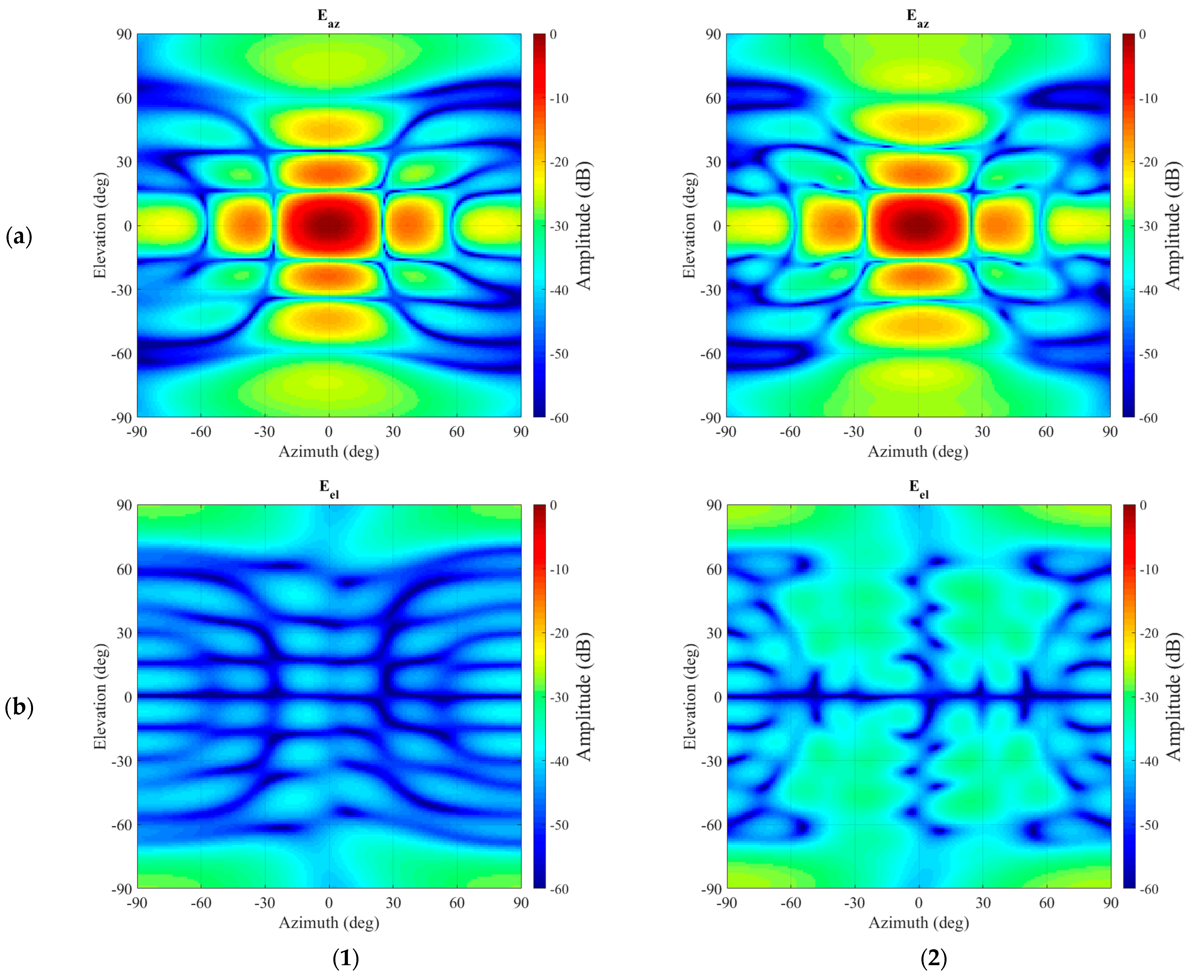
Figure 7. While the boresight peak seems largely unaffected, for azimuth and elevation angles of
circa 30° and greater, the differences in spurious interfering side-lobes from the parasitically coupled scatterer become increasingly evident in both the principal and cross-polarised field components. Here, the azimuth field component contains the co-polarization signal, and the elevation field component contains the cross-polarization signal. While clearly the disturbance is visible in the co-polarization component, it is very pronounced in the cross-polarization.
Utilizing the perturbed dataset that was contaminated with the PEC interference, the novel spherical mode-filtering reflection suppression algorithm was applied. The revised spherical mode-filtering reflection suppression algorithm relies upon the same physical phenomena and theory as prior implementations. However, it consists of fewer, more generally applicable steps when compared with those presented in earlier publications, cf. [
6], for example. The generalized revised approach can be summarized as follows:
The antenna under test is displaced from the origin of the measurement sphere in a known direction and distance, ;
A spherical (near-field) measurement is performed with a sufficiently fine angular sampling resolution to provide the unaliased mode spectrum required to describe the offset antenna pattern function;
A spherical wave expansion is used to compute the spherical mode coefficient of the measurement;
Probe pattern compensation is applied to the computed set of spherical modes (this was not required in this case, as an ideal electric Hertzian dipole probe was used within the SNF CEM simulation);
The spherical mode coefficients are translated to the origin by means of the translation matrix described above;
The translated set of SMCs is filtered to extract the deleterious scattered modes, cf. [
6];
Finally, a spherical wave summation is applied to attain the mode-filtered far-field pattern.
The calculation of the translation matrix used in step 5 for the given problem takes approximately 8 s, which, however, can be precalculated and reused for subsequent antenna measurements having the same offset and frequency. This can be further reduced if the highest-order N-mode in the output spectrum after translation is reduced (which is expected as the AUT moves towards the phase center). In cases of varying antenna sizes, a larger (up to higher-order N-modes) translation matrix can be precalculated, and for smaller antennas, only a subset of the matrix is utilized. Assuming a precalculated translation matrix, step 5 takes only 0.1 s versus 0.2 s for the same general operation of the original algorithm. Note, the degree of orthogonalization attained between antenna and parasitically coupled scattering modes is largely dependent upon the magnitude of the AUT offset and is largely independent of the measurement radius [
5,
6].
Figure 8 presents a comparison between the resulting far-field pattern after the application of the mode-filtering and the unperturbed far-field pattern. It can be seen, especially while comparing
Figure 7 and
Figure 8, that even though some residue of the unwanted, originally very significant interference persists in the far-field pattern, the vast majority of the spurious side-lobes in the azimuth (co-) polarization have been largely attenuated with the resulting pattern being in far closer agreement with the unperturbed reference far-field antenna pattern. The improvements in the cross-polarization are more difficult to assess, considering the relatively low signal levels contained within the reference pattern. However, the large lobes that were initially evident in the intercardinal region at
circa 30° have been very effectively suppressed.
By way of a further examination of the validity and reliability of the revised mode-filtering algorithm, a careful comparison against the traditional approach was undertaken. While the presented method in itself is expected only to attain significant benefits in those cases where the evanescent modes of the antenna in the near-field become more significant or when attempting to extract isolated single element radiating properties from array antenna measurements, which, it is important to note, was one of the primary applications and motivation of the spherical mode-filtering approach [
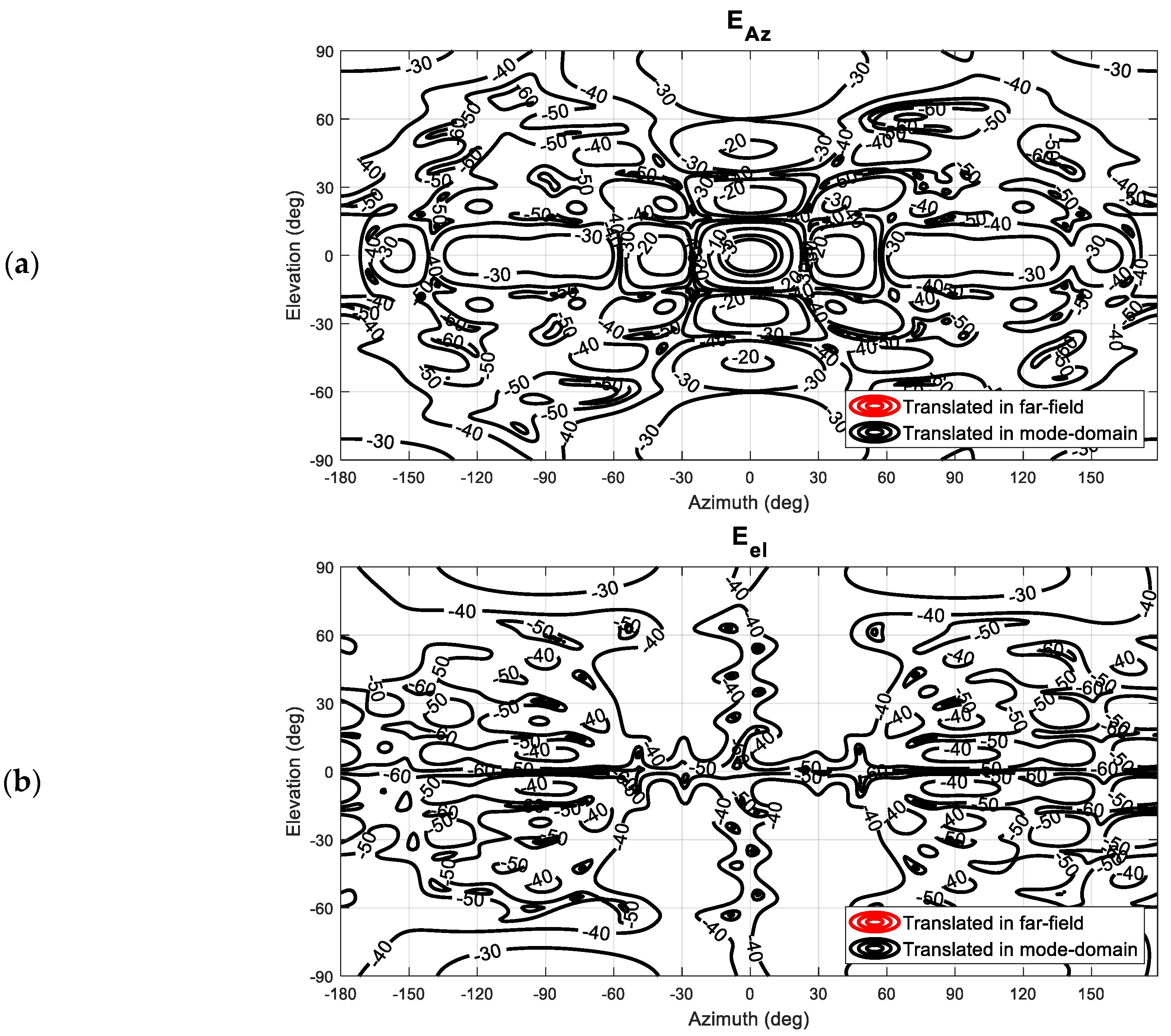
6], it is important to verify equivalence with the existing approach within the region of validity. Thus, although no improvements when compared with the existing far-field-based method are anticipated, it is important to investigate whether equally valid results are obtained. Therefore, the perturbed dataset was also transformed into the true far-field so that the test antenna could be mathematically translated back into the origin using the standard differential phase change approach. These far-fields were then used to compute the equivalent SMC, which were then filtered using the same cut-off as was used when processing with the new translation spherical mode-filtering reflection suppression was applied. This result can be seen compared in
Figure 9. Here, one can observe that both filtering methods provide nearly identical results. By way of a further comparison, the dB difference level [
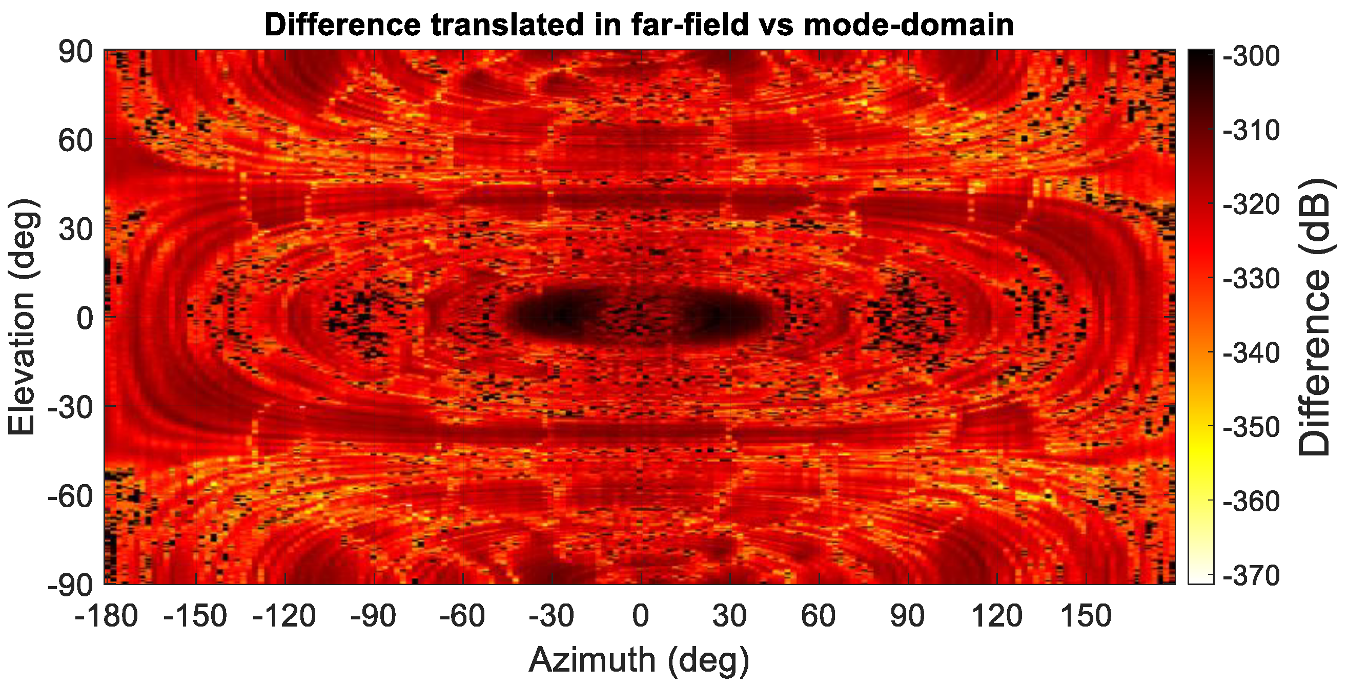
6] of both filtered far-field patterns is compared in
Figure 10, where their degree of agreement is nearing the limit of double-precision arithmetic.
Furthermore,
Figure 10 presents a false color checkerboard plot of the dB difference level between the results of the mode-filtering algorithms, indicating the extremely encouraging agreement attained. Thus, although the mode-filtering results demonstrate that not all of the parasitically coupled spurious scattered field has been extracted from the grossly contaminated simulated SNF measurement, the new algorithm is equally effective as the traditional approach, only with fewer transform operations being required and with the retention of any evanescent components.
Lastly, it is important to note that in this area of application, we are always translating AUT modes back towards the origin and
not reducing the total number of
N-modes. Thus, the mode-truncation effect is equal to the well-known truncation rules for spherical modes [
6] when considering an AUT measured at an offset position. However, for the alternative case where one is translating away from the origin (to a larger distance), then the output
N can increase; however, this too would be determined equivalently to the case where the AUT was measured offset at that position.
