Abstract
The traditional radio wave propagation models exhibit several limitations when they are employed to predict the path loss for vehicular ultra-shortwave wireless communication. To addresses these challenges, an optimized approach for Egli model based on the high-resolution remote sensing satellite image is proposed in this study. The optimization process includes three components. First, a method for calculating the actual equivalent antenna height is introduced, utilizing high-precision remote sensing satellite imagery to obtain communication path profiles. This method accounts for the antenna’s physical length, vehicular height, and local terrain characteristics, thereby providing an accurate representation of the antenna’s effective height within its operational environment. Second, an equivalent substitution method for ground loss is developed, utilizing surface information derived from high-precision remote sensing satellite images. This method integrates ground loss directly into the Egli model’s calculation process, eliminating the need for separate computations and simplifying the model. Third, leveraging the Egli model as a foundation, the least squares method (LSM) is employed to fit the relief height, ensuring the model meets the requirements for ultra-short wave communication distances under line-of-sight (LOS) conditions and enhances suitability for real-world vehicular communication systems. Finally, the validity and accuracy of the optimization model are verified by comparing the measured data with the theoretical calculated values. Compared with the Egli model, the Egli model with additional correction factors, and the measured data, the average error of the optimized model is reduced by 8.98%, 2.09%, and the average error is 0.45%.
1. Introduction
As a crucial component of modern wireless communication technology, vehicular ultra-shortwave communication has found extensive applications in military, public security, emergency rescue, and other critical fields [1,2,3,4,5,6]. Operating within the frequency band of 30 MHz to 300 MHz (very high frequency, VHF), this technology offers several advantages, including low propagation loss, strong diffraction capability, and excellent anti-interference performance, making it particularly suitable for communication in complex terrains and mobile environments. In recent years, with the rapid advancement of special vehicle technologies and intelligent transportation systems, there has been an increasing demand for higher reliability and practical performance in vehicular communication systems [7,8,9,10,11,12,13,14]. A key research focus in this domain has been the accurate prediction of radio wave propagation loss and the optimization of communication link performance, especially within line-of-sight (LOS) communication ranges [15,16,17,18,19,20].
In the context of diverse propagation scenarios, most loss report methodologies focus on fine-tuning propagation loss models. Previous studies have employed various optimization techniques: genetic algorithms for path loss model optimization [21] and particle swarm optimization demonstrating superior performance over genetic algorithms for Hata model tuning [22]. Additionally, the least-square approximation method has been widely adopted for path loss model optimization due to its simplicity and effectiveness in error minimization [23,24,25,26]. However, practical applications reveal that traditional radio wave propagation models (e.g., the Egli model and Okumura–Hata model) show limited accuracy in vehicular communication scenarios [27,28,29,30]. This limitation primarily stems from their inadequate consideration of critical factors such as terrain relief height, vehicle-mounted antenna heights, and surface loss [31,32,33,34]. Notably, while numerous tuning methods have been proposed, the Egli model has received comparatively less attention in the literature. The fundamental objective of all these optimization techniques remains consistent: to minimize prediction errors associated with propagation models. This underscores the significant engineering importance of developing high-precision radio wave propagation models specifically designed for ultra-shortwave vehicular communications [35,36,37,38,39,40]. Current propagation models applied to vehicular systems exhibit several critical limitations:
- (1)
- The operational frequency range of vehicular communication systems fails to align with the frequency specifications of conventional radio wave propagation loss models.
- (2)
- The vehicle-mounted antenna height configuration falls outside the optimal range defined by current radio wave propagation loss models.
- (3)
- The models lack comprehensive consideration of the terrain relief height influences on radio wave propagation loss.
In recent years, the rapid development of remote sensing technology has made the acquisition of remote sensing data more accessible, particularly high-resolution remote sensing images. High resolution remote sensing data enable city modeling for signal propagation analysis [41,42,43,44,45,46,47], with methods like SBL-based REM [42,44,47] offering ray-tracing capabilities. The high-resolution images support detailed urban modeling required for realistic propagation simulation, particularly for capturing urban structure effects like signal attenuation and diffraction losses in radio wave propagation model optimization. The application of high-resolution satellite remote sensing image to model optimization for vehicular communication systems has significant advantages, including improved accuracy and enhanced realism.
To address these limitations in the vehicular communication systems, an optimized approach to the Egli radio wave propagation model based on high-resolution satellite remote sensing imagery is proposed in this paper. The main contributions of this article are as follows:
- (1)
- Taking into account the altitude profile derived from high-precision remote sensing satellite images, along with the height of the vehicle and the physical length of the antenna, a method for calculating the actual equivalent antenna height is proposed. This method ensures a more accurate representation of the antenna’s effective height in relation to its environment.
- (2)
- Based on surface information derived from high-precision remote sensing satellite images and combined with the actual equivalent height of vehicle-mounted antennas an equivalent substitution method for surface loss is introduced. This method allows surface loss to be seamlessly integrated into the Egli model’s calculation process, eliminating the need for separate computations and thereby simplifying the overall model.
- (3)
- Leveraging the Egli model as a foundation, the least squares method (LSM) is employed to fit the terrain relief height. This fitting ensures that the model meets the requirements for ultra-short wave communication distances under LOS conditions.
The remainder of this paper is organized as follows. Section 2 presents the theoretical foundation, including (1) justification for selecting the Egli model and (2) the principles and advantages of applying LSM optimization to the Egli model. Section 3 details the three core optimization components: (1) computation of equivalent antenna height, (2) surface loss equivalent substitution, and (3) terrain relief height fitting. Section 4 validates the optimized model’s accuracy through field tests with vehicular communications and provides performance analysis. Finally, Section 5 concludes with key findings and their practical implications.
2. Model and Theoretical Basis
2.1. Model Selection
The selection of an appropriate propagation model is contingent upon meeting several critical technical specifications and operational requirements:
(1) The selected model must demonstrate effective radio wave propagation capabilities within the very high frequency (VHF) spectrum, particularly operating in the specified frequency range of 30–300 MHz, which corresponds to the ultra-shortwave communication band. Table 1 lists the operating frequency range of the classical radio wave propagation models.

Table 1.
The operating frequency range of the classical radio wave propagation models.
(2) The selected model should meet the requirements for LOS communication over distances of 15–30 km. Table 2 lists the propagation distance range of the classical radio wave propagation models.

Table 2.
The propagation distance range of the classical radio wave propagation models.
(3) The selected model must be compatible with vehicle-mounted antenna height configurations (typically 10–15 m above ground level) to ensure operational suitability in real-world communication scenarios. Table 3 lists the antenna height range of the classic radio wave propagation models.

Table 3.
The antenna height range of the classic radio wave propagation models.
(4) The selected model must account for moderately undulating irregular terrain, including hills, valleys, and urban environments. Table 4 lists the terrain requirements of the classical radio wave propagation models.

Table 4.
The terrain requirements of the classical radio wave propagation models.
The selection of the Egli model for optimization is selected through analysis of vehicular ultra-shortwave communication needs and systematic comparison of existing propagation models.
The Egli model (1957) [49], or “Hill Terrain Propagation Model with 50-Foot Average Slope Height,” is an empirical radio propagation model for irregular terrain. It predicts path loss for Frequency: 40–400 MHz (extendable to 1 GHz) and Distance: 0–64 km.
The Egli model’s radio wave propagation loss is given in Equation (1).
where is the radio wave frequency (MHz); and are the transmitting and receiving antenna heights (m); is the distance between the transmitting and receiving antenna (km); and is the terrain correction factor.
The terrain correction factor varies with radio frequency ranges, as specified in Equations (2)–(4).
where is the terrain relief height (m).
When , ; when , needs to be corrected.
2.2. Least Squares Method
The least squares method (LSM) is a mathematical optimization technique that determines the optimal function fitting a given dataset by minimizing the sum of squared residuals [53]. The exponential least squares model represents a nonlinear regression approach specifically designed to characterize data exhibiting exponential growth or decay patterns with respect to independent variables. Its general form is expressed as [54]:
where is the dependent variable; is the independent variable; and and are the parameters to be evaluated.
Due to the nonlinear nature of the exponential model, direct determination of parameters and using the LSM presents computational challenges. Typically, this problem can be addressed through linearization by applying the following transformation steps.
Let and , then Equation (6) is rewritten as Equation (7).
Following the least squares principle, we obtain the system of equations in Equation (8) by setting the partial derivatives with respect to and equal to zero.
where is the number of data points.
Equations (9)–(11) are obtained by solving Equation (8).
3. Optimization Process
The key process includes three components: (1) vehicle antenna effective height calculation, (2) surface loss equivalent substitution, and (3) terrain relief height fitting optimization. Each component is detailed below.
3.1. Actual Equivalent Antenna Height Calculation
Since vehicle-mounted antennas are significantly lower than base station antennas and vehicle height cannot be neglected, the effective antenna height becomes a critical parameter for model optimization, directly affecting the model’s accuracy. Figure 1 shows the illustration of actual equivalent antenna height.
where is the actual equivalent height of vehicle-mounted antenna (m); is the vehicular height (m); is the physical length of vehicle-mounted antenna (m); is the altitude at which the vehicle is located; and is the average altitude of the actual environment of vehicle communication.
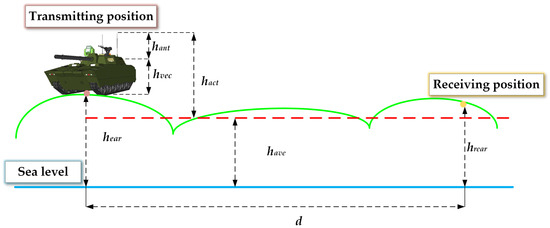
Figure 1.
Illustration of actual equivalent antenna height.
3.2. Surface Loss Equivalent Substitution
In ground communication systems, surface loss is a fundamental component of radio wave propagation model optimization that cannot be ignored. The reasons are as follows:
- (1)
- Energy absorption by the ground: when a vehicle engages in wireless communication on the ground, the ground absorbs a portion of the radio wave energy during propagation, leading to signal attenuation. The extent of energy absorption varies depending on the ground type, such as soil, water, vegetation, or urban structures.
- (2)
- Terrain irregularities: irregular terrain features such as hills, valleys, and urban structures can scatter, reflect, and diffract radio waves, distorting their propagation path and reducing signal strength.
- (3)
- Frequency dependency: the surface loss is related to the working frequency. In the VHF band, the interaction between radio waves and the ground becomes more pronounced, resulting in greater energy loss.
- (4)
- Impact on communication distance: in vehicular communication systems, the proximity of both the transmitter and receiver to the ground leads to significant surface loss, which markedly diminishes signal strength and directly impacts the system’s effective communication distance.
The operational frequency range of vehicular ultra-shortwave communication radios typically spans from 30 MHz to 88 MHz. In this frequency band, as the height of the vehicle antenna decreases, the contribution of ground waves becomes increasingly significant. When the antenna height is reduced to a certain critical value, known as the minimum effective antenna height , surface losses can no longer be neglected. Vehicular communication systems are typically equipped with vertically polarized whip antennas. The minimum effective antenna height of such an antenna can be determined using Equation (13).
where is the ground’s relative permittivity; is the ground’s conductivity (S/m); and is the radio wave length (m).
The equivalent antenna height is obtained from Equation (14). Substituting into the Egli model eliminates separate surface loss calculations. This optimization simplifies the model’s computation while maintaining accuracy.
where is the actual equivalent antenna height (m).
3.3. Terrain Relief Height Fitting
As described in Section 2.1, the Egli model adjusts based on empirical curves derived from extensive measurements [49], establishing the functional relationship between and in Equation (15).
Equation (15) establishes a positive correlation between and . As communication distance increases, approaches an asymptotic limit. When reaches 90% of asymptotic value (Equation (16)), the propagation distance can be derived (Equation (17)).
The maximum LOS communication distance for vehicle VHF radio is 30 km—only one-third of the theoretical value calculated in Equation (17). This significant discrepancy in tactical wireless communication range is addressed by incorporating Section 3.1 and Section 3.2.
When reaches 90% of asymptotic value (Equation (19)), the propagation distance can be calculated using Equation (20).
Equation (20) shows that the propagation distance calculated using the least-squares-fitted Equation (18) satisfies vehicular VHF radio communication distance requirements.
3.4. Optimized Egli Model
By incorporating the actual equivalent antenna height, surface loss, and fitted terrain relief height into the Egli model, an optimized version of the model is obtained as shown in Equation (21). Figure 2 illustrates the vehicle-to-vehicle (VTV) communication scenario.
where and are the physical heights (m) of antennas mounted on Vehicle 1 and Vehicle 2, respectively; and denote the vehicle body heights (m) of Vehicle 1 and Vehicle 2; and and indicate the terrain altitudes (m) at the locations of Vehicle 1 and Vehicle 2.
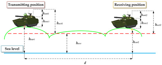
Figure 2.
The vehicle-to-vehicle (VTV) communication scenario.
4. Optimized Model Verification and Analysis
4.1. Communication Path Modeling
The communication experimental subject of this study is a specialized vehicle (Figure 3). Two such vehicles, labeled VEC 1 and VEC 2, are used in the experiments. VEC 1 serves as transmitting ends and VEC 2 acts as the receiving end.
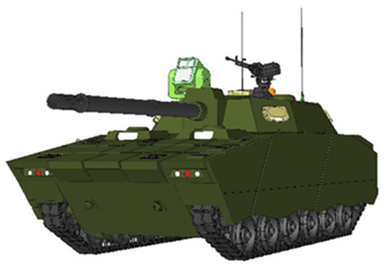
Figure 3.
Vehicle 3D model.
The experimental scene is in a specific urban area of Beijing. Figure 4 shows the satellite remote sensing image of the urban area, with an effective resolution of 5 m after fusion processing. Figure 5 shows the communication path.
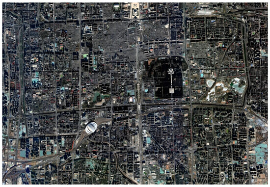
Figure 4.
Satellite remote sensing image of the urban area.
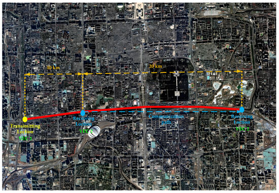
Figure 5.
Communication path.
As shown in Figure 6, the altitude profile along the communication path can be accurately derived from satellite remote sensing imagery. In urban environments, the maximum elevation variation is below 90 m, while the communication distance between the two vehicles ranges from 10 km to 30 km, satisfying the LOS propagation conditions.
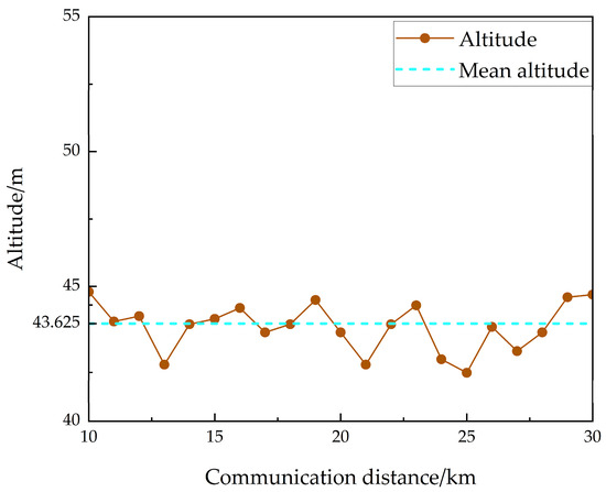
Figure 6.
Altitude profile along the communication path.
This provides essential data for calculating the actual antenna height. Additionally, key propagation parameters along the communication path (the ground’s relative permittivity and conductivity) can be determined, as shown in Table 5. This enables accurate surface loss modeling through equivalent substitution.

Table 5.
Key propagation parameters along the communication path.
4.2. Experimental Validation
VEC 1 is equipped with two antennas measuring 10 m and 15 m in length, respectively, while VEC 2 carries two antennas with lengths of 12 m and 15 m. Table 6 lists the vehicle-mounted radio and antenna parameters of the two vehicles. The working frequency of the radio on VEC 1 is selected at four different points: 40 MHz, 50 MHz, 70 MHz, and 80 MHz. Figure 7, Figure 8, Figure 9 and Figure 10 show the radio wave propagation loss under various conditions.

Table 6.
Vehicle-mounted radio and antenna parameters.
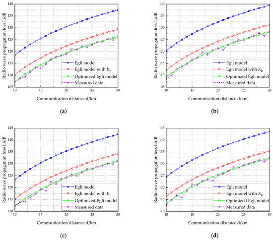
Figure 7.
Radio wave propagation loss (, ). (a) f = 40 MHz, (b) f = 50 MHz, (c) f = 70 MHz, (d) f = 80 MHz.
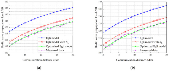
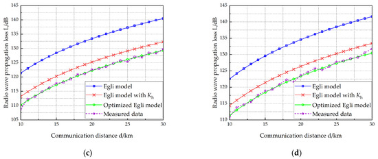
Figure 8.
Radio wave propagation loss (, ). (a) f = 40 MHz, (b) f = 50 MHz, (c) f = 70 MHz, (d) f = 80 MHz.
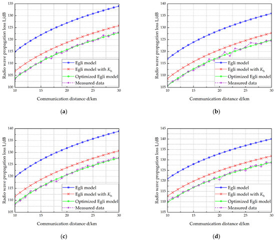
Figure 9.
Radio wave propagation loss (, ). (a) f = 40 MHz, (b) f = 50 MHz, (c) f = 70 MHz, (d) f = 80 MHz.
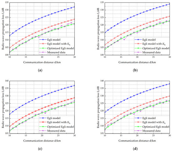
Figure 10.
Radio wave propagation loss (, ). (a) f = 40 MHz, (b) f = 50 MHz, (c) f = 70 MHz, (d) f = 80 MHz.
4.3. Result Analysis
The Mean Relative Error (MRE), defined in Equation (22), quantifies the deviation between calculated and measured values. To evaluate the accuracy of the optimized model, this chapter employs MRE as the key metric for assessing discrepancies between model predictions and field measurements.
where denotes the measured value; represents the theoretically calculated value; and is the total number of samples
Using Equation (22), we compute the MRE for three models: (1) the Egli model, (2) the terrain-corrected Egli model, and (3) the optimized model. Table 7 presents the calculated MRE values for each model, along with the reduction in MRE achieved by the improved model over both the original and terrain-corrected Egli models. Table 7 demonstrates that:

Table 7.
Radio wave propagation loss errors and comparison.
- (1)
- The Egli model exhibits an average relative error of 9.43% compared to measured data.
- (2)
- With terrain correction factors, the modified Egli model reduces average relative error to 2.54%.
- (3)
- The optimized model demonstrates significantly improved accuracy, with an average relative error of only 0.45%.
- (4)
- Compared to the Egli model, the optimized version achieves an 8.98% reduction in average relative error.
- (5)
- Compared to the terrain-corrected Egli model, the optimization yields a further 2.09% improvement in accuracy.
4.4. Model Analysis
Analysis of the results confirms the effectiveness of the optimized Egli model, demonstrating its improved accuracy for radio wave propagation loss prediction in specialized vehicular scenarios. The model is particularly suitable for applications meeting the following conditions:
- (1)
- Frequency range: VHF band (30–88 MHz);
- (2)
- Communication mode: LOS propagation (≤30 km range);
- (3)
- Terrain type: Gently undulating landscapes (relief height ≤ 90 m).
5. Conclusions
An integrated approach to enhance the accuracy and practicality of propagation modeling for vehicular communication systems is proposed in this study. First, we introduce a method to determine the actual equivalent antenna height by combining high-resolution remote sensing satellite data, vehicle height, and antenna dimensions, ensuring precise elevation representation. Second, we develop an equivalent substitution method for surface loss, integrating terrain data derived from remote sensing with the calculated equivalent antenna height. This method directly incorporates surface loss into the Egli model, eliminating standalone computations and simplifying the modeling process. Finally, using the Egli model as a framework, we optimize terrain relief height fitting via the LSM for ultra-shortwave LOS communication. Experimental validation demonstrates a 2.09% improvement in accuracy compared to the terrain-corrected Egli model. Collectively, these contributions advance terrain-aware radio propagation prediction while preserving computational efficiency.
Author Contributions
Conceptualization, H.L., G.Z. and P.C.; methodology, G.Z.; software, G.Z. and F.W.; validation, S.Z. and Y.Q.; data curation, Q.X., T.L. and S.Z.; writing—original draft preparation, G.Z.; writing—review and editing, H.L. All authors have read and agreed to the published version of the manuscript.
Funding
This research was funded by the National Defense Research Project, grant number JZX7X201901JY0048.
Data Availability Statement
The complete dataset is subject to approval, but contour maps, topographic profiles, and some pieces of vehicle information are open source and sufficient to support the reproduction of this paper. Details can be found in “Construction and Analysis of the EMC Evaluation Model for Vehicular Communication Systems Based on Digital Maps” published in Remote Sensing.
Acknowledgments
We are grateful to all the staff of a section of the Northern Vehicle Research Institute for their support in the experiments and measurements.
Conflicts of Interest
The authors declare no conflicts of interest. The funders had no role in the design of the study.
References
- Aiello, O.; Crovetti, P. Characterization of the Susceptibility to EMI of a BMS IC for Electric Vehicles by Direct Power and Bulk Current Injection. IEEE Lett. Electromagn. Compat. Pract. Appl. 2021, 3, 101–107. [Google Scholar] [CrossRef]
- He, C.; Qu, G.; Wei, S. A Vehicular Communication Routing Algorithm Based on Graph Theory. In Proceedings of the 2021 International Wireless Communications and Mobile Computing (IWCMC), Harbin, China, 28 June–2 July 2021; pp. 2176–2181. [Google Scholar]
- Lee, J.; Na, W. A Survey on Vehicular Communication Methods. In Proceedings of the 2022 13th International Conference on Information and Communication Technology Convergence (ICTC), Jeju Island, Republic of Korea, 19–21 October 2022; pp. 2258–2260. [Google Scholar]
- Azman, A.; Yogarayan, S.; Jian, S.L.W.; Razak, S.F.A.; Raman, K.J.; Abdullah, M.F.A.; Ibrahim, S.Z.; Amin, A.H.M.; Muthu, K.S. Comprehensive Study of Wireless Communication Technologies for Vehicular Communication. In Proceedings of the 2018 3rd International Conference on Computer and Communication Systems (ICCCS), Nagoya, Japan, 27–30 April 2018; pp. 314–317. [Google Scholar]
- Ai, Y.; de Figueiredo, F.A.P.; Kong, L.; Cheffena, M.; Chatzinotas, S.; Ottersten, B. Secure Vehicular Communications Through Reconfigurable Intelligent Surfaces. IEEE Trans. Veh. Technol. 2021, 70, 7272–7276. [Google Scholar] [CrossRef]
- Ahmed, R.; Kumbhar, F.H. VC3: A Novel Vehicular Compatibility-Based Cooperative Communication in 5G Networks. IEEE Wirel. Commun. Lett. 2021, 10, 1207–1211. [Google Scholar] [CrossRef]
- Hosseini, M.; Kurt, G.K. A Robust Clustering Scheme for Vehicular Communication Networks. In Proceedings of the 2024 IEEE 100th Vehicular Technology Conference (VTC2024-Fall), Washington, DC, USA, 7–10 October 2024; pp. 1–6. [Google Scholar]
- Zhang, W.; Zhou, Z.; Ge, C.; Wang, P. Data-driven Vehicular Communications in Urban Vehicular Network. In Proceedings of the 2019 IEEE 11th International Conference on Communication Software and Networks (ICCSN), Chongqing, China, 12–15 June 2019; pp. 1–8. [Google Scholar]
- Ali, R.; Hakro, D.N.; Tanweer, M.R.; Kamboh, A.A. Simulation based Vehicle to Vehicle and base station communication. In Proceedings of the 2019 International Conference on Information Science and Communication Technology (ICISCT), Karachi, Pakistan, 9–10 March 2019; pp. 1–6. [Google Scholar]
- Aghaei, F.; Uysal, M.; De Lamare, R.C.; Landau, L.T.N. Vehicular MMW Communication: Channel Characterization Based on Ray Tracing Study. In Proceedings of the 2024 19th International Symposium on Wireless Communication Systems (ISWCS), Rio de Janeiro, Brazil, 14–17 July 2024; pp. 1–6. [Google Scholar]
- Liang, L.; Peng, H.; Li, G.Y.; Shen, X. Vehicular Communications: A Physical Layer Perspective. IEEE Trans. Veh. Technol. 2017, 66, 10647–10659. [Google Scholar] [CrossRef]
- Ai, Y.; Cheffena, M.; Mathur, A.; Lei, H. On Physical Layer Security of Double Rayleigh Fading Channels for Vehicular Communications. IEEE Wirel. Commun. Lett. 2018, 7, 1038–1041. [Google Scholar] [CrossRef]
- Kurebayashi, Y.; Taya, A.; Tobe, Y. Environment-Dependent Throughput Distribution Estimation Based on Bayesian Approach for mmWave Vehicular Communications. In Proceedings of the 2023 IEEE 97th Vehicular Technology Conference (VTC2023-Spring), Florence, Italy, 20–23 June 2023; pp. 1–5. [Google Scholar]
- Gyawali, S.; Xu, S.; Qian, Y.; Hu, R.Q. Challenges and Solutions for Cellular Based V2X Communications. IEEE Commun. Surv. Tutor. 2021, 23, 222–255. [Google Scholar] [CrossRef]
- Körpe, E.; Akkaş, M.A.; Sokullu, R. Investigation of Environmental Effects in Terahertz Band Vehicular Communication. In Proceedings of the 2022 International Symposium on Multidisciplinary Studies and Innovative Technologies (ISMSIT), Ankara, Turkey, 20–22 October 2022; pp. 647–651. [Google Scholar]
- Gupta, S.; Purohit, K.C. Revolutionizing Mobility: A comprehensive Review of Vehicular Communication Networks. In Proceedings of the 2024 International Conference on Intelligent Computing and Sustainable Innovations in Technology (IC-SIT), Bhubaneswar, India, 21–23 November 2024; pp. 1–5. [Google Scholar]
- Thakur, A.; Khan, W.A.; Sagar, P.; Shah, A. An Approach for V2V Wireless Communication using Li-Fi and Wi-Fi Technology. In Proceedings of the 2024 5th International Conference on Smart Electronics and Communication (ICOSEC), Trichy, India, 18–20 September 2024; pp. 686–693. [Google Scholar]
- Körpe, E.; Akkaş, M.A.; Sokullu, R. Path Loss Analysis for Terahertz Band Single-Lane Vehicular Communication. In Proceedings of the 2023 31st Telecommunications Forum (TELFOR), Belgrade, Serbia, 21–22 November 2023; pp. 1–4. [Google Scholar]
- Petrov, V.; Eckhardt, J.M.; Moltchanov, D.; Koucheryavy, Y.; Kurner, T. Measurements of Reflection and Penetration Losses in Low Terahertz Band Vehicular Communications. In Proceedings of the 2020 14th European Conference on Antennas and Propagation (EuCAP), Copenhagen, Denmark, 15–20 March 2020; pp. 1–5. [Google Scholar]
- Zhang, Y.; Xu, W.; Jin, A.-L.; Tang, T.; Li, M.; Ma, P.; Jiang, L.; Gao, S. Enhanced Multidimensional Harmonic Retrieval in MIMO Wireless Channel Sounding. IEEE Internet Things J. 2025, 12, 16243–16255. [Google Scholar] [CrossRef]
- Oudira, H.; Diouane, L.; Garah, M. Empirical Path Loss Models Optimization for Mobile Communication. In Proceedings of the 2018 IEEE 5th International Congress on Information Science and Technology (CiSt), Marrakech, Morocco, 20–24 October 2018; pp. 443–448. [Google Scholar]
- Banimelhem, O.; Al-Zu’bi, M.M.; Al Salameh, M.S. Hata Path Loss Model Tuning for Cellular Networks in Irbid City. In Proceedings of the 2015 IEEE International Conference on Computer and Information Technology; Ubiquitous Computing and Communications; Dependable, Autonomic and Secure Computing; Pervasive Intelligence and Computing, Liverpool, UK, 26–28 October 2015; pp. 1646–1650. [Google Scholar]
- Cota, N.; Serrador, A.; Vieira, P.; Beire, A.R.; Rodrigues, A. On the Use of Okumura–Hata Propagation Model on Railway Communications. Wirel. Pers. Commun. 2017, 93, 725–736. [Google Scholar] [CrossRef]
- Saidi, R.; Saidi, L.; el abidine Regai, Z. Contribution to the performance of mobile radio systems by optimizing the Okumura–Hata model by linear regression: Application to the city of Annaba in Algeria. Int. J. Electr. Eng. Inform. 2017, 9, 677–689. [Google Scholar] [CrossRef]
- Roslee, M.; Kwan, K.F. Optimization of Hata Propagation Prediction Model in Suburban Area in Malaysia. Prog. Electromagn. Res. C 2010, 13, 91–106. [Google Scholar] [CrossRef]
- Faruk, N.; Popoola, S.I.; Surajudeen-Bakinde, N.T.; Oloyede, A.A.; Abdulkarim, A.; Olawoyin, L.A.; Ali, M.; Calafate, C.T.; Atayero, A.A. Path Loss Predictions in the VHF and UHF Bands Within Urban Environments: Experimental Investigation of Empirical, Heuristics and Geospatial Models. IEEE Access 2019, 7, 77293–77307. [Google Scholar] [CrossRef]
- Erdem, M.; Saleem, A.; Gurbuz, O.; Ecemis, C.; Saeed, A. A Simple Analytical Model for THz Band Path Loss. IEEE Commun. Lett. 2023, 27, 996–1000. [Google Scholar] [CrossRef]
- Saravia, L.M.M.; Saravia, A.R.M.; Silva, M.M.; Castellanos, P.V.G. Prediction of Path Loss in Real-World Environments: Comparison of ITU-R P.1411 Models and Deep Learning. In Proceedings of the 2024 IEEE 1st Latin American Conference on Antennas and Propagation (LACAP), Cartagena de Indias, Colombia, 1–4 December 2024; pp. 1–2. [Google Scholar]
- Kumari, C.U.; Kora, P.; Meenakshi, K. Short Term and Long Term Path Loss Estimation in Urban, SubUrban and Rural Areas. In Proceedings of the 2019 3rd International Conference on Computing Methodologies and Communication (ICCMC), Erode, India, 27–29 March 2019; pp. 114–117. [Google Scholar]
- Park, J.; Jeon, H.-B.; Cho, J.; Chae, C.-B. Measurement-Based Close-In Path Loss Modeling With Diffraction for Rural Long-Distance Communications. IEEE Wirel. Commun. Lett. 2023, 12, 1334–1338. [Google Scholar] [CrossRef]
- Sharma, P.K.; Sharma, D.; Sai, T.V. Optimization of propagation path loss model in 4G wireless communication systems. In Proceedings of the 2018 2nd International Conference on Inventive Systems and Control (ICISC), Coimbatore, India, 19–20 January 2018; pp. 1245–1248. [Google Scholar]
- Mahmood, T.; Mohamed, W.Q.; Imran, O.A. Factors Influencing the Shadow Path Loss Model with Different Antenna Gains Over Large-Scale Fading Channel. In Proceedings of the 2021 International Conference on Artificial Intelligence and Mechatronics Systems (AIMS), Bandung, Indonesia, 28–30 April 2021; pp. 1–5. [Google Scholar]
- Jawhly, T.; Tiwari, R.C. The special case of Egli and Hata model optimization using least-square approximation method. SN Appl. Sci. 2020, 2, 1296. [Google Scholar] [CrossRef]
- Surajudeen-Bakinde, N.T.; Faruk, N.; Popoola, S.I.; Salman, M.A.; Oloyede, A.A.; A Olawoyin, L.; Calafate, C.T. Path loss predictions for multi-transmitter radio propagation in VHF bands using Adaptive Neuro-Fuzzy Inference System. Eng. Sci. Technol. Int. J. 2018, 21, 679–691. [Google Scholar] [CrossRef]
- De Piante, M.; Tonello, A.M.; Schiozzi, M.; Rinaldo, R. Indoor Path Loss Statistical Characterization and Modeling for the Broad VHF–UHF Band. IEEE Antennas Wirel. Propag. Lett. 2020, 19, 2315–2319. [Google Scholar] [CrossRef]
- da Silva Duarte, B.; Dias, M.H.C. Critical analysis of ITU-R P.1812 and Egli propagation models for LoRaWAN Networks. In Proceedings of the 2022 Symposium on Internet of Things (SIoT), São Paulo, Brazil, 24–28 October 2022; pp. 1–4. [Google Scholar]
- Delisle, G.Y.; Lefevre, J.-P.; Lecours, M.; Chouinard, J.-Y. Propagation loss prediction: A comparative study with application to the mobile radio channel. IEEE Trans. Veh. Technol. 1985, 34, 86–96. [Google Scholar] [CrossRef]
- Celik, G.; Aitalieva, A.; Celebi, H. Comparison of Empirical and Ray-Traced Based Channel Modeling on VHF Band. In Proceedings of the 2019 27th Signal Processing and Communications Applications Conference (SIU), Sivas, Turkey, 24–26 April 2019; pp. 1–4. [Google Scholar] [CrossRef]
- Fischer, J.; Ulbricht, G.; Koch, R. M2M-SCM: A Spatial Channel Model for Mobile-to-Mobile Communications in the VHF and UHF Band. In Proceedings of the 2022 Tenth International Symposium on Computing and Networking Workshops (CANDARW), Himeji, Japan, 21–22 November 2022; pp. 1–6. [Google Scholar]
- Galkin, B.; Ho, L.; Lyons, K.; Celik, G.; Claussen, H. Experimental Evaluation of Air-to-Ground VHF Band Communication for UAV Relays. In Proceedings of the 2023 IEEE International Conference on Communications Workshops (ICC Workshops), Rome, Italy, 28 May–1 June 2023; pp. 1428–1432. [Google Scholar]
- Wang, Y.; Li, Y.; Zhang, S. Automatic Detection of War-Destroyed Buildings from High-Resolution Remote Sensing Images. Remote Sens. 2025, 17, 509. [Google Scholar] [CrossRef]
- Huang, D.-H.; Wu, S.-H.; Wu, W.-R.; Wang, P.-H. Cooperative radio source positioning and power map reconstruction: A sparse Bayesian learning approach. IEEE Trans. Veh. Technol. 2015, 64, 2318–2332. [Google Scholar] [CrossRef]
- Yuan, B.; Sehra, S.S.; Chiu, B. Multi-Scale and Multi-Network Deep Feature Fusion for Discriminative Scene Classification of High-Resolution Remote Sensing Images. Remote Sens. 2024, 16, 3961. [Google Scholar] [CrossRef]
- Wang, J. Sparse Bayesian learning-based 3D radio environment map construction—Sampling optimization, scenario-dependent dictionary construction, and sparse recovery. IEEE Trans. Cognit. Commun. Netw. 2024, 10, 80–93. [Google Scholar] [CrossRef]
- Tan, Y.; Sun, K.; Wei, J.; Gao, S.; Cui, W.; Duan, Y.; Liu, J.; Zhou, W. STFNet: A Spatiotemporal Fusion Network for Forest Change Detection Using Multi-Source Satellite Images. Remote Sens. 2024, 16, 4736. [Google Scholar] [CrossRef]
- Gu, X.; Yu, S.; Huang, F.; Ren, S.; Fan, C. Consistency Self-Training Semi-Supervised Method for Road Extraction from Remote Sensing Images. Remote Sens. 2024, 16, 3945. [Google Scholar] [CrossRef]
- Wang, J.; Zhu, Q.; Lin, Z.; Chen, J.; Ding, G.; Wu, Q.; Gu, G.; Gao, Q. Sparse Bayesian Learning-Based Hierarchical Construction for 3D Radio Environment Maps Incorporating Channel Shadowing. IEEE Trans. Wirel. Commun. 2024, 23, 14560–14574. [Google Scholar] [CrossRef]
- Friis, H.T. A Note on a Simple Transmission Formula. Proc. IRE 1946, 34, 254–256. [Google Scholar] [CrossRef]
- ITU-R P.1546-5; Method for Point-to-Area Predictions for Terrestrial Services in the Frequency Range 30 MHz to 3000 MHz. International Telecommunication Union: Geneva, Switzerland, 2013.
- Egli, J.J. Radio propagation above 40 mc over irregular terrain. Proc. IRE 1957, 45, 1383–1391. [Google Scholar] [CrossRef]
- Longley, A.G.; Rice, P.L. Prediction of Tropospheric Radio Transmission Loss over Irregular Terrain: A Computer Method; ESSA Technical Report, ERL 79-ITS 67; Institute for Telecommunication Sciences: Boulder, Colorado, 1968.
- Okumura, Y. Field Strength and Its Variability in VHF and UHF Land Mobile Service. Rev. Electr. Commun. Lab. 1968, 19, 825–837. [Google Scholar]
- Hata, M. Empirical Formula for Propagation Loss in Land Mobile Radio Services. IEEE Trans. Veh. Technol. 1980, VT-29, 317–325. [Google Scholar] [CrossRef]
- Björck, Å. Numerical Methods for Least Squares Problems; SIAM: Philadelphia, PA, USA, 1996. [Google Scholar]
Disclaimer/Publisher’s Note: The statements, opinions and data contained in all publications are solely those of the individual author(s) and contributor(s) and not of MDPI and/or the editor(s). MDPI and/or the editor(s) disclaim responsibility for any injury to people or property resulting from any ideas, methods, instructions or products referred to in the content. |
© 2025 by the authors. Licensee MDPI, Basel, Switzerland. This article is an open access article distributed under the terms and conditions of the Creative Commons Attribution (CC BY) license (https://creativecommons.org/licenses/by/4.0/).