1. Introduction
Slot antennas of various shapes are becoming attractive for many modern wireless communications applications that need low-cost and low-profile components that can be seamlessly integrated into microwave frontends. A great effort has been made to improve upon the slot antenna design and to face different challenges posed by their potential use in Internet of Things (IoT) [
1], wireless body area networks (WBANs) [
2], RFID [
3], and sensor network applications [
4]. Slot antennas of a simple shape [
5,
6,
7] can achieve a wide impedance bandwidth, but with very low gain, which is typically less than 5 dBi. Gain enhancement usually requires a complex feed structure [
8], resulting in demanding antenna design, or the use of a slot antenna array which increases the overall antenna size [
4]. The use of two feed ports is very common for slot antennas in order to achieve both right-hand and left-hand circular polarization [
6] or to provide simultaneous use of two operating modes [
2]. Therefore, the isolation between ports must also be considered and optimized to enable desired antenna functionality. Furthermore, slot antennas are usually used in complex communication systems with sensitive receivers; thus the front-to-back (FBR) gain ratio should be considered too.
This paper presents a simple two-port butterfly-shaped slot antenna designed at 2.4 GHz. The antenna is intended for full-duplex in-band applications in Doppler biosensing radars [
9]. In recent years significant advancement in biomedical radar technology has been focused on miniaturization, increased accuracy, and enhanced sensitivity [
10,
11]. The proposed antenna with two mutually isolated ports, which can be used for simultaneous transmit and receive in short-range radars, allows for considerable miniaturization of the radar hardware. Since the radiating slots that form the butterfly arms of the antenna are orthogonally positioned, this antenna is also a double-polarized antenna that exhibits almost identical radiation patterns in the E and H planes. By implementing two types of feed methods, it is possible to simultaneously receive both vertically and horizontally polarized waves at the different antenna ports, as is required for comprehensive polarimetric analysis of physiological Doppler radar signatures [
12,
13]. Although the antenna is designed for the 2.4 GHz band, it can be easily scaled to any other frequency band due to its simplicity.
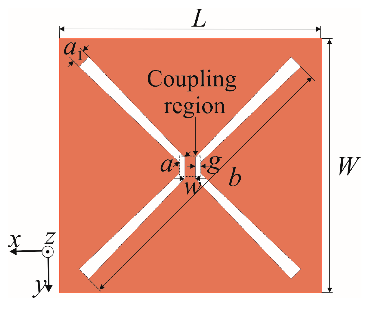
In our previous work on a one-port antenna with butterfly-shaped slots intended for K band applications, the antenna was fed by single coplanar waveguide (CPW) [
14] or microstrip line (MSL) [
15], both positioned along the coupling region. In this novel design of a two-port antenna at 2.4 GHz, the microstrip line is placed perpendicularly both to the coupling region and to the CPW line, to increase isolation between antenna ports. Unlike previously published two-port crossed-slot antennas [
16,
17,
18,
19,
20,
21], this novel design consists of two identical butterfly arms that are coupled through the region defined by the width and gap of the CPW feed line. In addition to the butterfly slot length and width dimensions, the parameters of the coupling region and the extension of the feed lines create more flexibility in the antenna optimization to achieve the same resonant frequency and input impedance at both antenna ports. Therefore, the proposed antenna does not require the complicated feed network and matching circuit that is needed in the other two-port crossed-slot antenna for adjustment of the resonant frequency and impedance at both ports [
16,
17,
18,
19,
20,
21]. The proposed butterfly slot antenna is designed using only one substrate with two conductive layers and fed by very simple CPW and MS lines, avoiding redundant bulky feed networks that introduce attenuation and increase overall antenna size. This is the simplest proposed dual-port, dual-polarization antenna design on a single substrate. Due to the antenna simplicity, a unique dual-port linear array is also proposed featuring eight butterfly slots and two feeding structures implemented on the same substrate, making antenna array modeling and fabrication simple and cost-effective.
After a brief discussion on recent advancements in the design of dual-polarized antennas in
Section 2,
Section 3 presents design and optimization results for a double-port butterfly slot antenna fed by microstrip and CPW lines, with and without extensions for fine adjustment of the antenna resonant frequency and the input impedance. The design and characteristics of a linear array of eight double-port butterfly slot antennas is given in
Section 4. Experimental results for the antenna prototype are presented in
Section 5 to validate the proposed design. A summary conclusion is given in
Section 6.
2. Related Works
The recent growth of wireless communication services requiring an antenna with polarization diversity has generated significant interest in dual-polarized antennas. In addition to the low-profile, high-gain, and broad bandwidth that is required for an antenna in most wireless applications, multipolarized antennas also require high isolation between the ports and low cross-polarization levels.
Dual-polarized antenna can be realized using simple planar configurations such as patch [
21,
22] or slot [
23,
24] antennas, with only one substrate and two conductive layers. The low-profile and compact size of such antennas [
23,
24] are suitable for applications where miniaturization is critical. However, the gain of these antennas is usually below 6 dBi, which is not sufficient in modern wireless communication. Also, their radiation patterns have omnidirectional or bidirectional properties causing a small front-to-back ratio.
Two identical radiating elements crossed at the right angle [
16,
17,
18,
19,
20,
21,
22] are commonly applied to achieve dual polarizations. Moreover, the crossed slots or patch antenna can lead to a dual-polarized radiation pattern with an identical radiation pattern in the E and H planes by implementing the appropriate feeding structure. The dual-polarized antenna presented in [
22] features different radiation patterns in the E and H planes. For the antenna intended for a comprehensive polarimetric study of physiological Doppler radar signatures [
12,
13], where a multipath fading problem can occur, it is important that the antenna can simultaneously receive both vertically and horizontally polarized waves at the different antenna ports from different directions. Therefore, the design of an antenna featuring identical radiation patterns in the E and H planes, especially its feeding structure, can be challenging.
The antennas proposed in [
16,
17,
18,
19,
20] use multilayered structures with more substrates to achieve dual-polarized properties and identical radiation patterns in the E and H planes. Although the radiation elements of the antennas in [
16,
17,
18,
19,
20] have a simple structure of two crossed identical shapes, its feeding structure, usually at both ports, is complex. The antenna presented in [
16] has fork-shaped feeding structures printed on a different substrate than the radiating elements, and it requires parasitic strips to reduce cross-polarization. The balun feeding structure is frequently used in the design of a dual-port dual-polarized antenna [
17]. However, its realization with a pair of split ring lines on two substrates makes the antenna assembly complex and challenging. Moreover, the pair of coupled meander lines has to be carefully modeled to achieve the desired antenna performance [
17]. The antenna from [
18] consists of interdigital structures between the square patch edges and the thin metallic strips loaded with metallic vias. The radiating elements of the antenna presented in [
19] use two substrates to improve antenna radiation characteristics. Moreover an additional substrate is added to realize a power divider necessary for one port excitation and additional isolation from second port interference [
20].
The antenna proposed in [
21] uses only one substrate; however its feeding structure, implemented with two coaxial lines with inner and outer conductors excited out of phase, is complex.
The aim of the presented work is to design a dual-polarized antenna with an identical radiation pattern in the E and H planes for both ports, with a simple feeding method and a good front-to-back ratio. Two identical butterfly slots crossed at the right angle were considered with a reflector that suppresses back radiation. The butterfly slot antenna can be easily integrated into an array employing the CPW series and MSL corporative feeding network. The array can be easily realized by simultaneously printing radiating elements and series feeding on the top side and a corporate feeding network on the bottom side. The array does not need balun as in the array in [
25], vias between the array elements and corporative feeding network as in the array in [
26], or 50 Ω coaxial lines between the antenna elements and dividers as in the array in [
27].
4. Linear Dual-Port Array of the Butterfly Slot Antenna
A high-gain antenna is crucial in some biosensing applications, especially when precision and reliability are important for system functionality. In the case of significant signal attenuation through biological tissue or long-distance directional communication, it is necessary to enhance sensitivity to very weak emitted signals. The antenna array is usually used to achieve the requested high gain. A proposed single-substrate design, without a need for complicated matching circuits, is particularly suitable for a low-cost array design. Unlike rectangular crossed slots where only width and length can be optimized [
28,
29], the coupled butterfly slot antenna can be simply incorporated in a dual-port array thanks to additional opportunities to adjust antenna resonant frequency and impedance at both ports simultaneously.
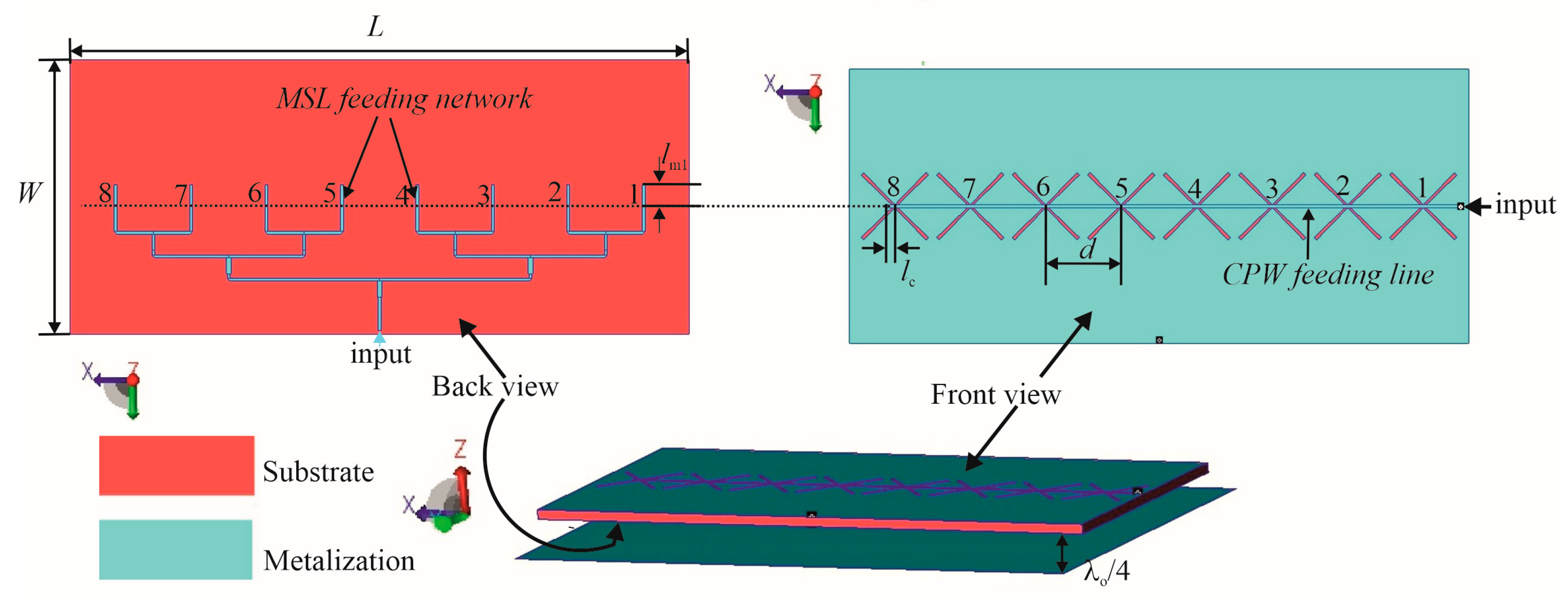
As proof of principle, a linear array of the dual-port butterfly slot antennas has been designed in WIPL-D Pro CAD 2023 software [
30], and its details are shown in
Figure 7.
The array features eight dual-port butterfly slot antennas positioned along the x-axis on the top side of the FR4 substrate. The distance between elements in the array is determined mainly by series feeding, in which the input power to the antenna comes from one end of the array by the CPW line. With this end feeding, the main beam angle will be very sensitive to frequency change due to the progressive phase change of the series-fed elements. To avoid the main beam squint at the central frequency, the distance between radiating elements should be equal to the wavelength of the CPW feeding line d = λgcpw, (λgcpw = 80 mm is the wavelength of CPW feeding line at the center frequency fc), where λgcpw = 0.64λ0 and where λ0 is the free-space wavelength at the frequency fc = 2.4 GHz.
Moreover, the butterfly shape of the antenna requires enough space between neighboring slots to prevent overlapping of their wings. The CPW line is extended over the last slot for the length lc.
On the bottom side of the substrate, there is the corporative microstrip network consisting of impedance transformers, widely used in antenna design [
31,
32], and also enabling uniform distribution for the array’s elements. Its eight microstrip lines extending over the slot center for
lm1 are positioned orthogonally on the CPW line from the substrate top side. The CPW and MS lines have the characteristic impedance
Zc, featuring the dimensions specified in the
Section 3.
As proof of concept, an analysis of mutual coupling between two identical butterfly slot antennas positioned at the distance
dis (center to center) was conducted and is depicted in
Figure 8a. The CPW ports are labeled as c while the MSL ports are labeled as m. The minimum distance in the graph in
Figure 8 is determined by the length of the butterfly wings preventing their overlap. Also,
Figure 8a shows that the influence between MSL ports is greater than the influence between CPW ports or between MSL and CPW ports.
Further analysis studies the mutual coupling between two identical butterfly slot antennas but with one intermediate slot element (
Figure 8b). The distance
dis between antennas is uniform. However, the influence between CPW ports is dominant here.
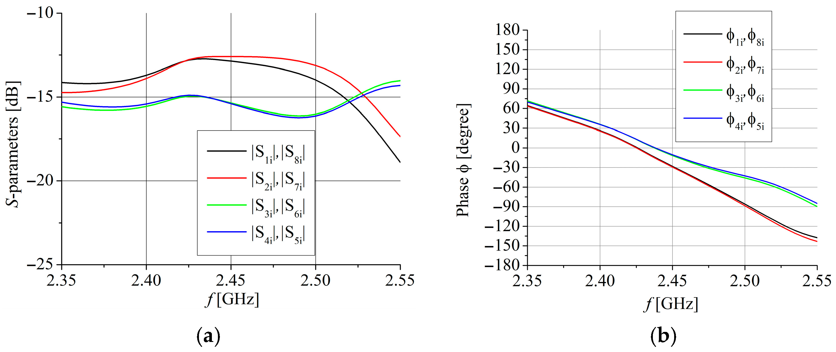
Figure 9 presents magnitude and phase distribution at the output ports of the MSL corporative feeding network in
Figure 7.
Figure 10 presents magnitude and phase distribution for the elements in the array obtained by CPW series feeding where, for clarity, only results for the elements of the array with odd ordinal numbers are given. Numerical labels for magnitude and phase distribution match numerical labels of the array’s elements from
Figure 7.
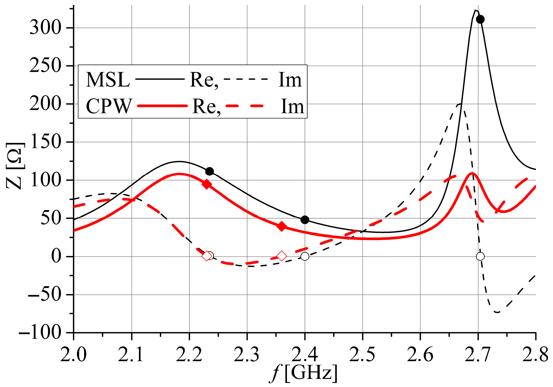
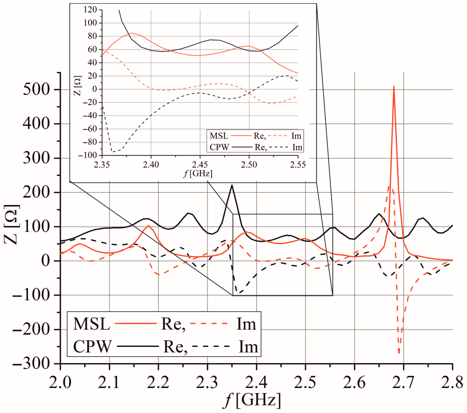
Figure 11 shows the optimized input impedance of the array at each port separately. The impedance at both ports has a few resonances in the considered frequency range, but the dimensions of the radiating slots are adjusted to exhibit the impedance
Zc at frequencies between 2.4 GHz and 2.55 GHz.
Figure 12 confirms the results from
Figure 11, showing that the simulated
S11 parameter is less than −10 dB for the frequency range 2.4 GHz to 2.54 GHz and the
S22 parameter is less than −10 dB for the frequency range 2.385 GHz to 2.54 GHz.
Figure 12 also shows that the simulated
S21 parameter is around −20 dB in the range between 2.4 GHz and 2.54 GHz.
Figure 13 and
Figure 14 depict simulated radiation patterns in the
xz-plane (
φ = 0°) and in the
yz-plane (
φ = 90°) at the frequency of 2.4 GHz with feeding by the CPW and by microstrip port, respectively. The array fed from a CPW port has maximum gain 14.6 dBi and the SLS (side lobe suppression) of 11.9 dB in the E plane. As an opposite to the single dual-port slot antenna, the antenna array fed from an MSL port has a greater maximum gain of 16.7 dBi and the SLS of 12.3 dB in the E plane. It is mainly caused by the fact that the MSL port feeds the array through a corporative feeding network while CPW is the series feeding type. Although the CPW series feeding offers a simpler feeding network, it requires that the input signal passes through all antenna elements sequentially, which increases overall transmission losses and signal uncertainties.
The most important radiation characteristics of the linear dual-port array are given in
Table 1. Keeping in mind all presented results, the linear dual-port array can be considered as a good choice for many full-duplex biosensing applications requesting a dual-port antenna as a sink node that is required to feature high performances, such as high gain [
33].
5. Experimental Results of a Single Antenna
The proposed two dual-port butterfly slot antennas shown in
Figure 2 are simulated and optimized using WIPL-D Pro CAD software [
30] to obtain the antenna’s input impedance equal to the characteristic impedance of the feeding lines
Zc. However, the reflector plate, which has the same dimensions as the substrate, does not achieve an adequate front-to-back ratio. As a result, the size of the reflector plate is optimized to enhance the antenna’s front-to-back ratio.
The magnitudes of the simulated
S11 and
S22 parameters, corresponding to feeding by the CPW port and microstrip port, respectively, are displayed in
Figure 15.
The simulated
S11 is less than −10 dB for frequency range 2.34 GHz to 2.525 GHz for Antenna 1 and 2.23 GHz to 2.415 GHz for Antenna 2. Similarly, the
S22 is less than −10 dB for frequency range 2.34 GHz to 2.51 GHz for Antenna 1 and 2.275 GHz to 2.475 GHz for Antenna 2. It can be seen that all results in
Figure 15 correspond very well with the simulated results for the input impedance shown in
Figure 3 and
Figure 4. Since both antennas have very similar simulated
S21 parameters, as shown in
Figure 16, only Antenna 1 is fabricated and measured.
Photographs of the fabricated antenna prototype are depicted in
Figure 17. Measurements of the antenna prototype, conducted in a wide frequency range, demonstrate a strong correlation with the simulation results. The magnitudes of the measured
S11 and
S22 parameters are depicted in
Figure 15. The measured impedance bandwidth (
S11,
S22 < −10 dB) is from 2.35 GHz to 2.55 GHz, which is 8.33% of the center frequency
fc. The measured isolation between ports (magnitude of
S21 parameter) is greater than 25 dB for the frequency range between 2 GHz and 2.47 GHz (
Figure 16). In general, S-parameters obtained by antenna measurement show very good agreement with simulations shown in
Figure 15 and
Figure 16. A small frequency shift between simulation and measurement of about 25 MHz for
S11, 40 MHz for
S22, and 10 MHz for the
S21 parameters is likely due to printing tolerances and cable and connector effects during the measurements.
The measured peak gains
G and efficiency for the CPW and MS ports are presented in
Figure 18 and
Figure 19, respectively. The measured peak gains
G is obtained using the measured
S-parameters of two identical fabricated antennas (
G =
G1 =
G2) at the distance
r = 1.76 m by the formula:
The value of peak gain at the CPW feeding port varies between 7 dBi and 8.5 dBi within the impedance bandwidth. However, peak gain is a bit lower when the microstrip port feeds the antenna, and it fluctuates between 6.5 dBi and 7.75 dBi in the same bandwidth. The greater peak gain, when the CPW port is employed, is also obtained by simulation (
Figure 18 and
Figure 19). Therefore, it can be concluded that the obtained measured peak gains are in close agreement with the simulated values. Also, for both ports, CPW and MSL, measured efficiency is greater than 80% in the whole operating band, with a value of 90% for the CPW port and 83% for the MS port at
fc.
The measured radiation patterns in the
xz-plane (
φ = 0°) and in the
yz-plane (
φ = 90°) with feeding by the CPW port and microstrip port for the frequencies 2.3 GHz, 2.4 GHz, and 2.5 GHz are depicted in
Figure 20 and
Figure 21, respectively. Although there are slight differences in the backside radiation that can come from the measuring system and environment, which is generally at a low level, the simulated and measured patterns show good agreement for both feeding ports used. Moreover, the radiation patterns in examined planes, the
xz-plane (
φ = 0°) and
yz-plane (
φ = 90°) for the CPW port, are almost the same as the
yz-plane and
xz-plane radiation patterns for the microstrip port. Therefore, the E and H planes’ radiation patterns for the CPW port are almost the same as the radiation patterns in the H and E planes for the microstrip port. Also, both port excitations feature similar radiation patterns in the E and H planes. In summary, it is observed that the proposed antenna can simultaneously receive both vertical and horizontal polarization at different antenna ports.
Table 2 gives the review of the most important measured characteristics of the proposed antenna. It can be noticed that measured port isolation is around 25 dB and the measured efficiency is above 80% in the whole impedance bandwidth. Also, the gain fluctuates between 6.5 dBi and 8.5 dBi in the concerned frequency range. But, the front-to-back ratio is mostly between 15 dB and 20 dB, except for a few measurements at 2.3 GHz. These measured results are important if the antenna is intended for application in the systems sensitive to unwanted electromagnetic radiation. Also, if the antenna is included in WBAN wireless system, it will have less effect on the body, due to its reduced back-feeding radiation. Further, cross-polarization level is lower for the CPW port, and it ranges from −23 dB to −13.5 dB. If the antenna is fed from the microstrip port, the cross-polarization level is between −20 dB and −10 dB.
Moreover, the antenna rotated for ±45 degrees can be used for precise polarimetric Doppler radar respiratory measurements [
9] to enhance the signal to noise ratio (SNR) of the systems.
Figure 22 shows V-polar and H-polar radiation patterns for the antenna rotated for 45 degrees.
It can be perceived that signals with both polarizations appear equally at both antenna ports, which differ mutually in broadside direction.
Table 3 compares the proposed antenna and six previously published dual-port antennas mostly designed at the similar frequency range. All considered antennas are chosen to meet the specific requirements set by full-duplex in-band applications in Doppler biosensing radars: dual-polarized dual port, with reflector to suppress back radiation, and with identical radiation patterns in the E and H planes, i.e., identical corresponding radiation patterns at both ports. The antennas with demanding feeding structure design require two or more substrates and more conductive layers [
16,
17,
18,
19,
20], which results in complex assembly and increases modeling and manufacturing time and overall antenna cost. The antenna presented in [
21] is realized on one substrate with two conductive layers but with large overall dimensions. Additionally, it is fed by two coax lines whose outer conductor is joined to one antenna point while the inner conductor is connected to another antenna point, demanding short pins to enable a 180-phase difference between the inner and outer conductors’ excitations. In contrast, the proposed antenna with only one substrate and two conductive layers uses an extremely simple, in-plane feeding structure consisting of a very short microstrip and CPW line and achieves a comparable performance. Unlike some antennas from
Table 3 that are designed to feature broadband characteristics, the proposed antenna has a narrow bandwidth because it was designed for applications at a 2.4 GHz ISM band. However, the antenna is easily scalable for other frequency bands [
14,
15]. The array of proposed antennas fed by the microstrip line enabling tapered distribution was presented in [
34] and the array with a CPW corporative feeding network with uniform distribution was shown [
35], both intended for a frequency range from 24 GHz to 27 GHz.
The use of a single substrate with two conductive layers makes this design easy to fabricate. There is no need for additional design and mounting of a supplementary feeding network and components like balun [
17], interdigital structures [
18], power divider [
20], etc., which introduce attenuation, increase antenna size, and make the fabrication more expensive.
