
Design and Demonstration of a Hybrid FES-BCI-Based Robotic Neurorehabilitation System for Lower Limbs

 ,
,  , and
, and
Abstract
1. Introduction
2. Materials and Methods
2.1. System Design
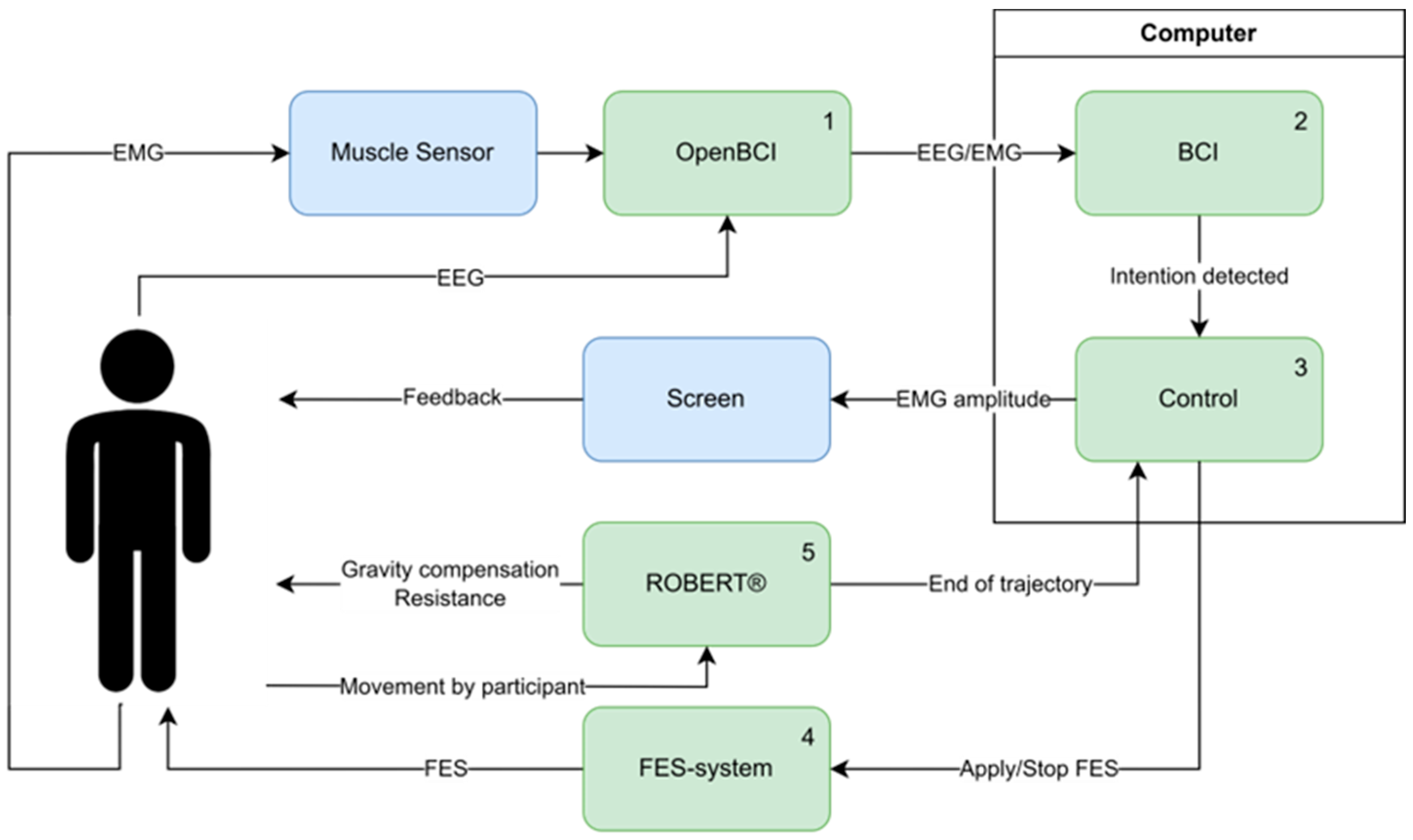
2.1.1. Hardware
2.1.2. Brain–Computer Interface
2.2. Experimental Procedure
2.2.1. Participants
2.2.2. Participant Preparation
2.2.3. BCI Calibration and Data Acquisition
2.2.4. BCI-Triggered Exercise
2.3. Data Acquisition
- You felt comfortable with the exercise.
- You did not experience pain during the exercise.
- You got tired during the exercise.
- You enjoyed the exercise.
2.4. Data Analysis
3. Results
3.1. System Performance
3.2. System Feasibility
3.2.1. Time Spent Using the System
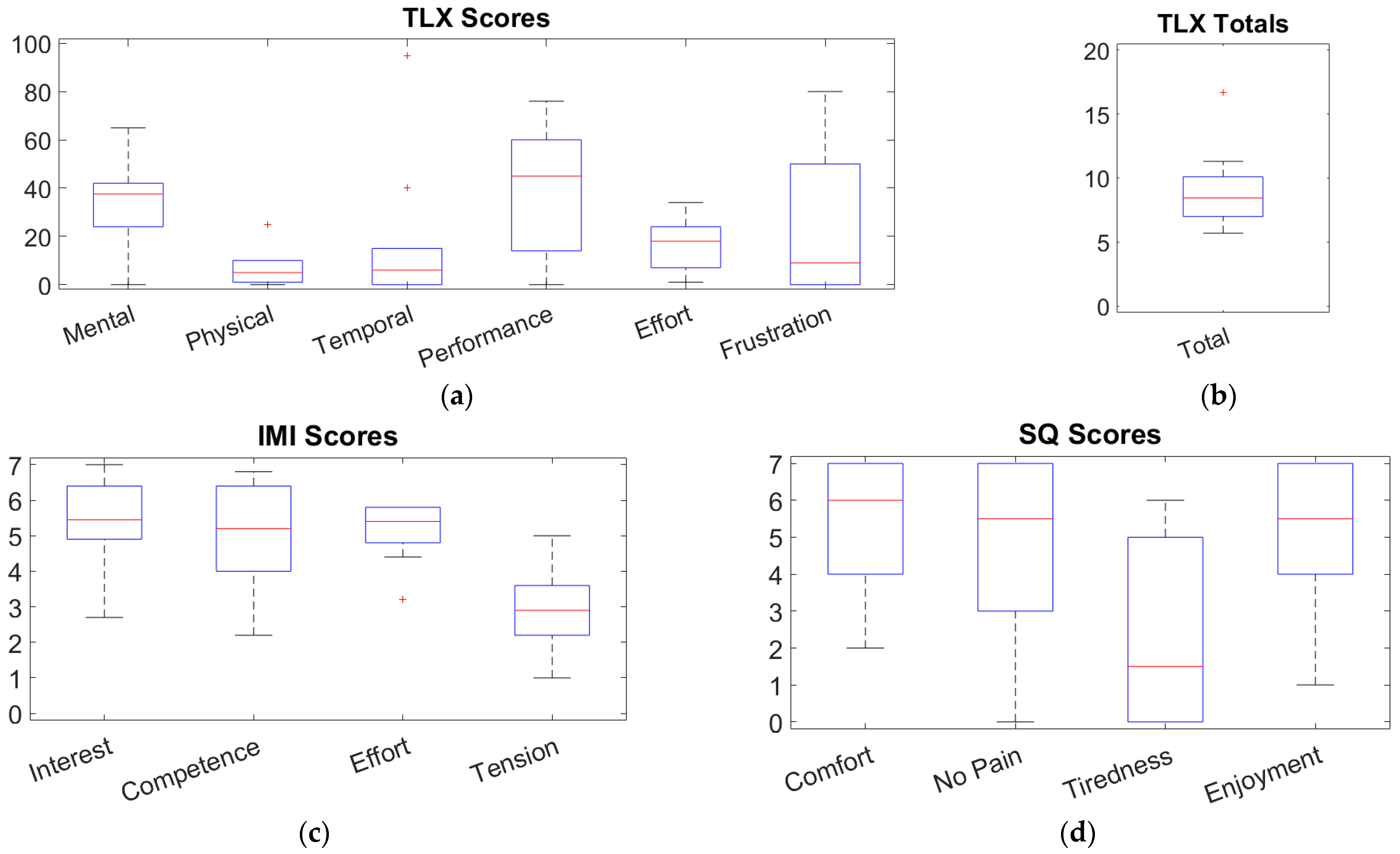
3.2.2. Questionnaires
4. Discussion
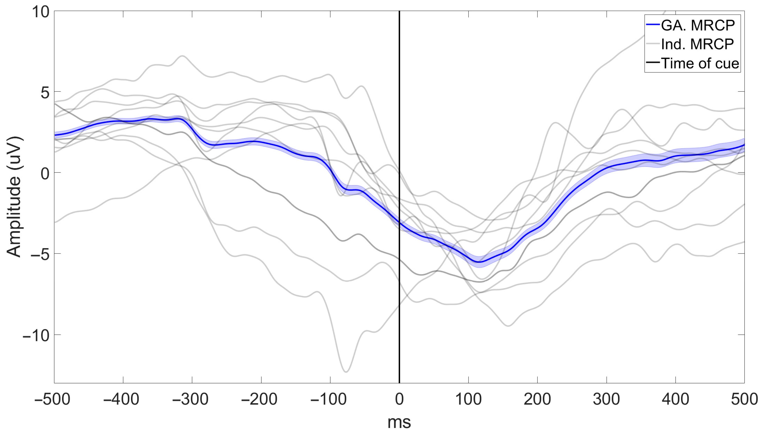
4.1. BCI Performance
4.2. Feasibility of the System
4.3. Feasibility of Inducing Neuroplasticity
4.4. Limitations
4.5. Future Studies
5. Conclusions
Author Contributions
Funding
Institutional Review Board Statement
Informed Consent Statement
Data Availability Statement
Acknowledgments
Conflicts of Interest
References
- Coleman, E.R.; Moudgal, R.; Lang, K.; Hyacinth, H.I.; Awosika, O.O.; Kissela, B.M.; Feng, W. Early Rehabilitation After Stroke: A Narrative Review. Curr. Atheroscler. Rep. 2017, 19, 59. [Google Scholar] [CrossRef] [PubMed]
- Bernhardt, J.; Hayward, K.S.; Kwakkel, G.; Ward, N.S.; Wolf, S.L.; Borschmann, K.; Krakauer, J.W.; Boyd, L.A.; Carmichael, S.T.; Corbett, D.; et al. Agreed Definitions and a Shared Vision for New Standards in Stroke Recovery Research: The Stroke Recovery and Rehabilitation Roundtable Taskforce. Int. J. Stroke 2017, 12, 444–450. [Google Scholar] [CrossRef] [PubMed]
- Dietz, V. Neuronal Plasticity after a Human Spinal Cord Injury: Positive and Negative Effects. Exp. Neurol. 2012, 235, 110–115. [Google Scholar] [CrossRef] [PubMed]
- Rethnam, V.; Langhorne, P.; Churilov, L.; Hayward, K.S.; Herisson, F.; Poletto, S.R.; Tong, Y.; Bernhardt, J. Early Mobilisation Post-Stroke: A Systematic Review and Meta-Analysis of Individual Participant Data. Disabil. Rehabil. 2022, 44, 1156–1163. [Google Scholar] [CrossRef] [PubMed]
- Pittaccio, S.; Garavaglia, L.; Molteni, E.; Guanziroli, E.; Zappasodi, F.; Beretta, E.; Strazzer, S.; Molteni, F.; Villa, E.; Passaretti, F. Can Passive Mobilization Provide Clinically-Relevant Brain Stimulation? A Pilot Eeg and Nirs Study on Healthy Subjects. In Proceedings of the 2013 35th Annual International Conference of the IEEE Engineering in Medicine and Biology Society (EMBC), Osaka, Japan, 3–7 July 2013; IEEE: Piscataway, NJ, USA, 2013; pp. 3547–3550. [Google Scholar]
- Scivoletto, G.; Morganti, B.; Molinari, M. Early versus Delayed Inpatient Spinal Cord Injury Rehabilitation: An Italian Study. Arch. Phys. Med. Rehabil. 2005, 86, 512–516. [Google Scholar] [CrossRef] [PubMed]
- Langhorne, P.; Collier, J.M.; Bate, P.J.; Thuy, M.N.T.; Bernhardt, J. Very Early versus Delayed Mobilisation after Stroke. Cochrane Database Syst. Rev. 2018, 10, CD006187. [Google Scholar] [CrossRef] [PubMed]
- Gracies, J. Pathophysiology of Spastic Paresis. I: Paresis and Soft Tissue Changes. Muscle Nerve Off. J. Am. Assoc. Electrodiagn. Med. 2005, 31, 535–551. [Google Scholar] [CrossRef] [PubMed]
- Huie, J.R.; Morioka, K.; Haefeli, J.; Ferguson, A.R. What Is Being Trained? How Divergent Forms of Plasticity Compete To Shape Locomotor Recovery after Spinal Cord Injury. J. Neurotrauma 2017, 34, 1831–1840. [Google Scholar] [CrossRef] [PubMed]
- Alingh, J.F.; Fleerkotte, B.M.; Groen, B.E.; Rietman, J.S.; Weerdesteyn, V.; van Asseldonk, E.H.F.; Geurts, A.C.H.; Buurke, J.H. Effect of Assist-as-Needed Robotic Gait Training on the Gait Pattern Post Stroke: A Randomized Controlled Trial. J. Neuroeng. Rehabil. 2021, 18, 26. [Google Scholar] [CrossRef] [PubMed]
- de Miguel-Fernández, J.; Lobo-Prat, J.; Prinsen, E.; Font-Llagunes, J.M.; Marchal-Crespo, L. Control Strategies Used in Lower Limb Exoskeletons for Gait Rehabilitation after Brain Injury: A Systematic Review and Analysis of Clinical Effectiveness. J. Neuroeng. Rehabil. 2023, 20, 23. [Google Scholar] [CrossRef] [PubMed]
- Louie, D.R.; Eng, J.J. Powered Robotic Exoskeletons in Post-Stroke Rehabilitation of Gait: A Scoping Review. J. Neuroeng. Rehabil. 2016, 13, 53. [Google Scholar] [CrossRef] [PubMed]
- Ayad, S.; Ayad, M.; Megueni, A.; Spaich, E.G.; Struijk, L.N.S.A. Toward Standardizing the Classification of Robotic Gait Rehabilitation Systems. IEEE Rev. Biomed. Eng. 2019, 12, 138–153. [Google Scholar] [CrossRef] [PubMed]
- Yildirim, M.A.; Öneş, K.; Gökşenoğlu, G. Early Term Effects of Robotic Assisted Gait Training on Ambulation and Functional Capacity in Patients with Spinal Cord Injury. Turk. J. Med. Sci. 2019, 49, 838–843. [Google Scholar] [CrossRef] [PubMed]
- Grasmücke, D.; Zieriacks, A.; Jansen, O.; Fisahn, C.; Sczesny-Kaiser, M.; Wessling, M.; Meindl, R.C.; Schildhauer, T.A.; Aach, M. Against the Odds: What to Expect in Rehabilitation of Chronic Spinal Cord Injury with a Neurologically Controlled Hybrid Assistive Limb Exoskeleton. A Subgroup Analysis of 55 Patients According to Age and Lesion Level. Neurosurg. Focus. 2017, 42, E15. [Google Scholar] [CrossRef] [PubMed]
- Ramanujam, A.; Cirnigliaro, C.M.; Garbarini, E.; Asselin, P.; Pilkar, R.; Forrest, G.F. Neuromechanical Adaptations during a Robotic Powered Exoskeleton Assisted Walking Session. J. Spinal Cord. Med. 2018, 41, 518–528. [Google Scholar] [CrossRef] [PubMed]
- Monaco, V.; Galardi, G.; Coscia, M.; Martelli, D.; Micera, S. Design and Evaluation of NEUROBike: A Neurorehabilitative Platform for Bedridden Post-Stroke Patients. IEEE Trans. Neural Syst. Rehabil. Eng. 2012, 20, 845–852. [Google Scholar] [CrossRef] [PubMed]
- Young, W. Electrical Stimulation and Motor Recovery. Cell Transplant. 2015, 24, 429–446. [Google Scholar] [CrossRef] [PubMed]
- Milosevic, M.; Marquez-Chin, C.; Masani, K.; Hirata, M.; Nomura, T.; Popovic, M.R.; Nakazawa, K. Why Brain-Controlled Neuroprosthetics Matter: Mechanisms Underlying Electrical Stimulation of Muscles and Nerves in Rehabilitation. Biomed. Eng. Online 2020, 19, 81. [Google Scholar] [CrossRef] [PubMed]
- Doucet, B.M.; Lam, A.; Griffin, L. Neuromuscular Electrical Stimulation for Skeletal Muscle Function. Yale J. Biol. Med. 2012, 85, 201–215. [Google Scholar] [PubMed]
- Hunt, K.J.; Fang, J.; Saengsuwan, J.; Grob, M.; Laubacher, M. On the Efficiency of FES Cycling: A Framework and Systematic Review. Technol. Health Care 2012, 20, 395–422. [Google Scholar] [CrossRef] [PubMed]
- Chou, L.-W.; Binder-Macleod, S.A. The Effects of Stimulation Frequency and Fatigue on the Force–Intensity Relationship for Human Skeletal Muscle. Clin. Neurophysiol. 2007, 118, 1387–1396. [Google Scholar] [CrossRef] [PubMed]
- del-Ama, A.J.; Gil-Agudo, Á.; Bravo-Esteban, E.; Pérez-Nombela, S.; Pons, J.L.; Moreno, J.C. Hybrid Therapy of Walking with Kinesis Overground Robot for Persons with Incomplete Spinal Cord Injury: A Feasibility Study. Rob. Auton. Syst. 2015, 73, 44–58. [Google Scholar] [CrossRef]
- Kirsch, N.; Alibeji, N.; Fisher, L.; Gregory, C.; Sharma, N. A Semi-Active Hybrid Neuroprosthesis for Restoring Lower Limb Function in Paraplegics. In Proceedings of the 2014 36th Annual International Conference of the IEEE Engineering in Medicine and Biology Society, Chicago, IL, USA, 26–30 August 2014; IEEE: Piscataway, NJ, USA, 2014; pp. 2557–2560. [Google Scholar]
- Gorgey, A.S. Robotic Exoskeletons: The Current Pros and Cons. World J. Orthop. 2018, 9, 112–119. [Google Scholar] [CrossRef] [PubMed]
- Anaya, F.; Thangavel, P.; Yu, H. Hybrid FES–Robotic Gait Rehabilitation Technologies: A Review on Mechanical Design, Actuation, and Control Strategies. Int. J. Intell. Robot. Appl. 2018, 2, 1–28. [Google Scholar] [CrossRef]
- Laursen, C.B.; Nielsen, J.F.; Andersen, O.K.; Spaich, E.G. Feasibility of Using Lokomat Combined with Functional Electrical Stimulation for the Rehabilitation of Foot Drop. Eur. J. Transl. Myol. 2016, 26, 268–273. [Google Scholar] [CrossRef] [PubMed]
- Mazzoleni, S.; Battini, E.; Rustici, A.; Stampacchia, G. An Integrated Gait Rehabilitation Training Based on Functional Electrical Stimulation Cycling and Overground Robotic Exoskeleton in Complete Spinal Cord Injury Patients: Preliminary Results. In Proceedings of the 2017 International Conference on Rehabilitation Robotics (ICORR), London, UK, 17–20 July 2017; IEEE: Piscataway, NJ, USA, 2017; pp. 289–293. [Google Scholar]
- Petersen, I.L.; Nowakowska, W.; Ulrich, C.; Struijk, L.N.S.A. A Novel SEMG Triggered FES-Hybrid Robotic Lower Limb Rehabilitation System for Stroke Patients. IEEE Trans. Med. Robot. Bionics 2020, 2, 631–638. [Google Scholar] [CrossRef]
- Dietz, V. Clinical Aspects for the Application of Robotics in Locomotor Neurorehabilitation. In Neurorehabilitation Technology; Springer International Publishing: Cham, Switzerland, 2016; pp. 209–222. [Google Scholar]
- Mrachacz-Kersting, N.; Jiang, N.; Stevenson, A.J.T.; Niazi, I.K.; Kostic, V.; Pavlovic, A.; Radovanovic, S.; Djuric-Jovicic, M.; Agosta, F.; Dremstrup, K.; et al. Efficient Neuroplasticity Induction in Chronic Stroke Patients by an Associative Brain-Computer Interface. J. Neurophysiol. 2016, 115, 1410–1421. [Google Scholar] [CrossRef] [PubMed]
- López-Larraz, E.; Trincado-Alonso, F.; Rajasekaran, V.; Pérez-Nombela, S.; del-Ama, A.J.; Aranda, J.; Minguez, J.; Gil-Agudo, A.; Montesano, L. Control of an Ambulatory Exoskeleton with a Brain–Machine Interface for Spinal Cord Injury Gait Rehabilitation. Front. Neurosci. 2016, 10, 359. [Google Scholar] [CrossRef] [PubMed]
- Chung, E.; Kim, J.-H.; Park, D.-S.; Lee, B.-H. Effects of Brain-Computer Interface-Based Functional Electrical Stimulation on Brain Activation in Stroke Patients: A Pilot Randomized Controlled Trial. J. Phys. Ther. Sci. 2015, 27, 559–562. [Google Scholar] [CrossRef] [PubMed]
- McGie, S.C.; Zariffa, J.; Popovic, M.R.; Nagai, M.K. Short-Term Neuroplastic Effects of Brain-Controlled and Muscle-Controlled Electrical Stimulation. Neuromodul. Technol. Neural Interface 2015, 18, 233–240. [Google Scholar] [CrossRef] [PubMed]
- Kuka LBR Med: Lightweight Cobot for Medical Applications. Available online: https://www.kuka.com/en-de/industries/robots-used-in-medicine/kuka-solutions-for-medical-robots/lbr-med-medical-robot (accessed on 2 July 2025).
- Leerskov, K.S.; Rikhof, C.J.H.; Spaich, E.G.; Dosen, S.; Prange-Lasonder, G.B.; Prinsen, E.C.; Rietman, J.S.; Struijk, L.N.S.A. A Robot-Based Hybrid Lower Limb System for Assist-As-Needed Rehabilitation of Stroke Patients: Technical Evaluation and Clinical Feasibility. Comput. Biol. Med. 2024, 179, 108839. [Google Scholar] [CrossRef] [PubMed]
- Maier, M.; Ballester, B.R.; Verschure, P.F.M.J. Principles of Neurorehabilitation After Stroke Based on Motor Learning and Brain Plasticity Mechanisms. Front. Syst. Neurosci. 2019, 13, 74. [Google Scholar] [CrossRef] [PubMed]
- Niazi, I.K.; Mrachacz-Kersting, N.; Jiang, N.; Dremstrup, K.; Farina, D. Peripheral Electrical Stimulation Triggered by Self-Paced Detection of Motor Intention Enhances Motor Evoked Potentials. IEEE Trans. Neural Syst. Rehabil. Eng. 2012, 20, 595–604. [Google Scholar] [CrossRef] [PubMed]
- Niazi, I.K.; Jiang, N.; Tiberghien, O.; Nielsen, J.F.; Dremstrup, K.; Farina, D. Detection of Movement Intention from Single-Trial Movement-Related Cortical Potentials. J. Neural Eng. 2011, 8, 066009. [Google Scholar] [CrossRef] [PubMed]
- Shakeel, A.; Navid, M.S.; Anwar, M.N.; Mazhar, S.; Jochumsen, M.; Niazi, I.K. A Review of Techniques for Detection of Movement Intention Using Movement-Related Cortical Potentials. Comput. Math. Methods Med. 2015, 2015, 346217. [Google Scholar] [CrossRef] [PubMed]
- SENIAM Recommendations for Sensor Locations in Hip or Upper Leg Muscles—Quadriceps Femoris (Rectus Femoris). Available online: http://seniam.org/quadricepsfemorisrectusfemoris.html (accessed on 22 May 2025).
- Botter, A.; Oprandi, G.; Lanfranco, F.; Allasia, S.; Maffiuletti, N.A.; Minetto, M.A. Atlas of the Muscle Motor Points for the Lower Limb: Implications for Electrical Stimulation Procedures and Electrode Positioning. Eur. J. Appl. Physiol. 2011, 111, 2461–2471. [Google Scholar] [CrossRef] [PubMed]
- Leerskov, K.S.; Dosen, S.; Spaich, E.G.; Lotte N.S., A.S. Increase and Decrease in Velocity and Force During Exercise with a Hybrid Robotic-FES Rehabilitation System. In Proceedings of the 2022 International Conference on Rehabilitation Robotics (ICORR), Rotterdam, The Netherlands, 25–29 July 2022; IEEE: Piscataway, NJ, USA, 2022; pp. 1–6. [Google Scholar]
- NASA TLX Paper and Pencil Version. Available online: http://humansystems.arc.nasa.gov/groups/tlx/downloads/TLXScale.pdf (accessed on 22 May 2025).
- Intrinsic Motivation Inventory (IMI). Available online: https://selfdeterminationtheory.org/intrinsic-motivation-inventory/ (accessed on 22 May 2025).
- Wang, Q.; Timmermans, A.; Chen, W.; Jia, J.; Ding, L.; Xiong, L.; Rong, J.; Markopoulos, P. Stroke Patients’ Acceptance of a Smart Garment for Supporting Upper Extremity Rehabilitation. IEEE J. Transl. Eng. Health Med. 2018, 6, 2101009. [Google Scholar] [CrossRef] [PubMed]
- Mazzoleni, S.; Turchetti, G.; Palla, I.; Posteraro, F.; Dario, P. Acceptability of Robotic Technology in Neuro-Rehabilitation: Preliminary Results on Chronic Stroke Patients. Comput. Methods Programs Biomed. 2014, 116, 116–122. [Google Scholar] [CrossRef] [PubMed]
- Xu, R.; Jiang, N.; Mrachacz-Kersting, N.; Lin, C.; Asin Prieto, G.; Moreno, J.C.; Pons, J.L.; Dremstrup, K.; Farina, D. A Closed-Loop Brain–Computer Interface Triggering an Active Ankle–Foot Orthosis for Inducing Cortical Neural Plasticity. IEEE Trans. Biomed. Eng. 2014, 61, 2092–2101. [Google Scholar] [CrossRef] [PubMed]
- Do, A.H.; Wang, P.T.; King, C.E.; Chun, S.N.; Nenadic, Z. Brain-Computer Interface Controlled Robotic Gait Orthosis. J. Neuroeng. Rehabil. 2013, 10, 111. [Google Scholar] [CrossRef] [PubMed]
- Liu, T.; Huang, G.; Jiang, N.; Yao, L.; Zhang, Z. Reduce Brain Computer Interface Inefficiency by Combining Sensory Motor Rhythm and Movement-Related Cortical Potential Features. J. Neural Eng. 2020, 17, 035003. [Google Scholar] [CrossRef] [PubMed]
- Jochumsen, M.; Knoche, H.; Kidmose, P.; Kjær, T.W.; Dinesen, B.I. Evaluation of EEG Headset Mounting for Brain-Computer Interface-Based Stroke Rehabilitation by Patients, Therapists, and Relatives. Front. Hum. Neurosci. 2020, 14, 13. [Google Scholar] [CrossRef] [PubMed]
- McCrimmon, C.M.; Fu, J.L.; Wang, M.; Lopes, L.S.; Wang, P.T.; Karimi-Bidhendi, A.; Liu, C.Y.; Heydari, P.; Nenadic, Z.; Do, A.H. Performance Assessment of a Custom, Portable, and Low-Cost Brain-Computer Interface Platform. IEEE Trans. Biomed. Eng. 2017, 64, 2313–2320. [Google Scholar] [CrossRef] [PubMed]
- English, K.L.; Paddon-Jones, D. Protecting Muscle Mass and Function in Older Adults during Bed Rest. Curr. Opin. Clin. Nutr. Metab. Care 2010, 13, 34–39. [Google Scholar] [CrossRef] [PubMed]
- Reidy, P.T.; McKenzie, A.I.; Brunker, P.; Nelson, D.S.; Barrows, K.M.; Supiano, M.; LaStayo, P.C.; Drummond, M.J. Neuromuscular Electrical Stimulation Combined with Protein Ingestion Preserves Thigh Muscle Mass But Not Muscle Function in Healthy Older Adults During 5 Days of Bed Rest. Rejuvenation Res. 2017, 20, 449–461. [Google Scholar] [CrossRef] [PubMed]
- Vasconcelos, B.; Fiedler, P.; Machts, R.; Haueisen, J.; Fonseca, C. The Arch Electrode: A Novel Dry Electrode Concept for Improved Wearing Comfort. Front. Neurosci. 2021, 15, 748100. [Google Scholar] [CrossRef] [PubMed]
- dos Santos, E.M.; San-Martin, R.; Fraga, F.J. Comparison of Subject-Independent and Subject-Specific EEG-Based BCI Using LDA and SVM Classifiers. Med. Biol. Eng. Comput. 2023, 61, 835–845. [Google Scholar] [CrossRef] [PubMed]
- von Groll, V.G.; Leeuwis, N.; Rimbert, S.; Roc, A.; Pillette, L.; Lotte, F.; Alimardani, M. Large Scale Investigation of the Effect of Gender on Mu Rhythm Suppression in Motor Imagery Brain-Computer Interfaces. Brain-Comput. Interfaces 2024, 11, 87–97. [Google Scholar] [CrossRef] [PubMed]
- van Hedel, H.J.A.; Dietz, V. Rehabilitation of Locomotion after Spinal Cord Injury. Restor. Neurol. Neurosci. 2010, 28, 123–134. [Google Scholar] [CrossRef] [PubMed]
- Leerskov, K.K.; Struijk, L.N.S.A.; Spaich, E.G. Assessment of Plastic Changes Following Bio-Robotic Rehabilitation of Spinal Cord Injured Individuals—A Protocol Proposal. In Converging Clinical and Engineering Research on Neurorehabilitation III; Springer: Berlin/Heidelberg, Germany, 2019; pp. 866–870. [Google Scholar]
- Mrachacz-Kersting, N.; Kristensen, S.R.; Niazi, I.K.; Farina, D. Precise Temporal Association between Cortical Potentials Evoked by Motor Imagination and Afference Induces Cortical Plasticity. J. Physiol. 2012, 590, 1669–1682. [Google Scholar] [CrossRef] [PubMed]
- Yao, L.; Chen, M.L.; Sheng, X.; Mrachacz-Kersting, N.; Zhu, X.; Farina, D.; Jiang, N. Common Spatial Pattern with Polarity Check for Reducing Delay Latency in Detection of MRCP Based BCI System. In Proceedings of the 2017 8th International IEEE/EMBS Conference on Neural Engineering (NER), Shanghai, China, 25–28 May 2017; IEEE: Piscataway, NJ, USA, 2017; pp. 544–547. [Google Scholar]
- Xu, R.; Jiang, N.; Lin, C.; Mrachacz-Kersting, N.; Dremstrup, K.; Farina, D. Enhanced Low-Latency Detection of Motor Intention From EEG for Closed-Loop Brain-Computer Interface Applications. IEEE Trans. Biomed. Eng. 2014, 61, 288–296. [Google Scholar] [CrossRef] [PubMed]
- Donati, A.R.C.; Shokur, S.; Morya, E.; Campos, D.S.F.; Moioli, R.C.; Gitti, C.M.; Augusto, P.B.; Tripodi, S.; Pires, C.G.; Pereira, G.A.; et al. Long-Term Training with a Brain-Machine Interface-Based Gait Protocol Induces Partial Neurological Recovery in Paraplegic Patients. Sci. Rep. 2016, 6, 30383. [Google Scholar] [CrossRef] [PubMed]
- Ang, K.K.; Guan, C.; Chua, K.S.G.; Ang, B.T.; Kuah, C.W.K.; Wang, C.; Phua, K.S.; Chin, Z.Y.; Zhang, H. A Large Clinical Study on the Ability of Stroke Patients to Use an EEG-Based Motor Imagery Brain-Computer Interface. Clin. EEG Neurosci. 2011, 42, 253–258. [Google Scholar] [CrossRef] [PubMed]
- Xu, R.; Jiang, N.; Vuckovic, A.; Hasan, M.; Mrachacz-Kersting, N.; Allan, D.; Fraser, M.; Nasseroleslami, B.; Conway, B.; Dremstrup, K.; et al. Movement-Related Cortical Potentials in Paraplegic Patients: Abnormal Patterns and Considerations for BCI-Rehabilitation. Front. Neuroeng. 2014, 7, 35. [Google Scholar] [CrossRef] [PubMed]
- Sun, Q.; Zhou, Y.; Gong, P.; Zhang, D. Attention Detection Using EEG Signals and Machine Learning: A Review. Mach. Intell. Res. 2025, 22, 219–238. [Google Scholar] [CrossRef]
- Rehman, A.U.; Shi, X.; Ullah, F.; Wang, Z.; Ma, C. Measuring Student Attention Based on EEG Brain Signals Using Deep Reinforcement Learning. Expert Syst. Appl. 2025, 269, 126426. [Google Scholar] [CrossRef]
- Kaushik, P.; Moye, A.; van Vugt, M.; Roy, P.P. Decoding the Cognitive States of Attention and Distraction in a Real-Life Setting Using EEG. Sci. Rep. 2022, 12, 20649. [Google Scholar] [CrossRef] [PubMed]


| Participant | BCI TPR (%) | BCI Latency (ms) |
|---|---|---|
| 1 | 75.0 | −737 ± 690 |
| 2 | 41.0 | −751 ± 727 |
| 3 | 85.7 | −554 ± 533 |
| 4 | 64.9 | −511 ± 579 |
| 5 | 67.7 | −489 ± 563 |
| 6 | 66.7 | −547 ± 773 |
| 7 | 57.8 | −439 ± 325 |
| 8 | 68.3 | −470 ± 648 |
| 9 | 59.4 | −786 ± 672 |
| 10 | 66.3 | −670 ± 542 |
| Average | 62.6 ± 9.2 | −595 ± 129 |
| Participant | Mounting Time (min) | Calibration Time (min) | Total Setup Time (min) | Exercise Time (min) | Total Time (min) | Per Repetition (s) |
|---|---|---|---|---|---|---|
| 1 | 13.1 | 17.3 | 30.4 | 44.2 | 74.6 | 97 |
| 2 | 9.5 | 18.1 | 27.6 | 60.4 | 88.0 | 53 |
| 3 | 13.6 | 24.7 | 38.3 | 52.7 | 91.0 | 46 |
| 4 | 11.2 | 24.8 | 36.0 | 58.8 | 94.8 | 47 |
| 5 | 9.5 | 22.2 | 31.7 | 55.5 | 87.2 | 40 |
| 6 | 12.3 | 20.0 | 32.3 | 59.3 | 91.6 | 39 |
| 7 | 9.3 | 21.9 | 31.2 | 54.4 | 85.6 | 51 |
| 8 | 9.0 | 20.4 | 29.4 | 56.8 | 86.2 | 37 |
| 9 | 10.0 | 21.7 | 31.7 | 58.5 | 90.2 | 45 |
| 10 | 8.5 | 18.3 | 26.8 | 55.3 | 82.1 | 41 |
| Average | 10.6 ± 1.7 | 20.9 ± 2.5 | 31.5 ± 3.3 | 55.6 ± 4.4 | 87.1 ± 5.4 | 44 ± 5 |
| Questionnaire | Subscale | Pearson Corr. (p-Value) |
|---|---|---|
| TLX | Mental | −0.351 (0.320) |
| Physical | 0.194 (0.591) | |
| Temporal | −0.022 (0.952) | |
| Performance | 0.065 (0.858) | |
| Effort | −0.521 (0.122) | |
| Frustration | 0.012 (0.975) | |
| Total | −0.217 (0.547) | |
| IMI | Interest | 0.330 (0.351) |
| Perceived Competence | 0.384 (0.274) | |
| Effort | −0.195 (0.589) | |
| Tension | 0.023 (0.951) | |
| SQ | Comfort | −0.111 (0.760) |
| No Pain | −0.189 (0.602) | |
| Tiredness | −0.214 (0.552) | |
| Enjoyment | 0.442 (0.201) |
Disclaimer/Publisher’s Note: The statements, opinions and data contained in all publications are solely those of the individual author(s) and contributor(s) and not of MDPI and/or the editor(s). MDPI and/or the editor(s) disclaim responsibility for any injury to people or property resulting from any ideas, methods, instructions or products referred to in the content. |
© 2025 by the authors. Licensee MDPI, Basel, Switzerland. This article is an open access article distributed under the terms and conditions of the Creative Commons Attribution (CC BY) license (https://creativecommons.org/licenses/by/4.0/).
Share and Cite
Leerskov, K.S.; Spaich, E.G.; Jochumsen, M.R.; Andreasen Struijk, L.N.S. Design and Demonstration of a Hybrid FES-BCI-Based Robotic Neurorehabilitation System for Lower Limbs. Sensors 2025, 25, 4571. https://doi.org/10.3390/s25154571
Leerskov KS, Spaich EG, Jochumsen MR, Andreasen Struijk LNS. Design and Demonstration of a Hybrid FES-BCI-Based Robotic Neurorehabilitation System for Lower Limbs. Sensors. 2025; 25(15):4571. https://doi.org/10.3390/s25154571
Chicago/Turabian StyleLeerskov, Kasper S., Erika G. Spaich, Mads R. Jochumsen, and Lotte N. S. Andreasen Struijk. 2025. "Design and Demonstration of a Hybrid FES-BCI-Based Robotic Neurorehabilitation System for Lower Limbs" Sensors 25, no. 15: 4571. https://doi.org/10.3390/s25154571
APA StyleLeerskov, K. S., Spaich, E. G., Jochumsen, M. R., & Andreasen Struijk, L. N. S. (2025). Design and Demonstration of a Hybrid FES-BCI-Based Robotic Neurorehabilitation System for Lower Limbs. Sensors, 25(15), 4571. https://doi.org/10.3390/s25154571