
Current Sensor with Optimized Linearity for Lightning Impulse Current Measurement

Abstract
1. Introduction
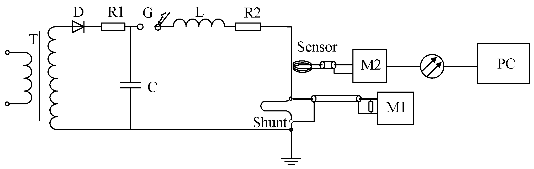
2. Lightning Impulse Current Measurement Sensor
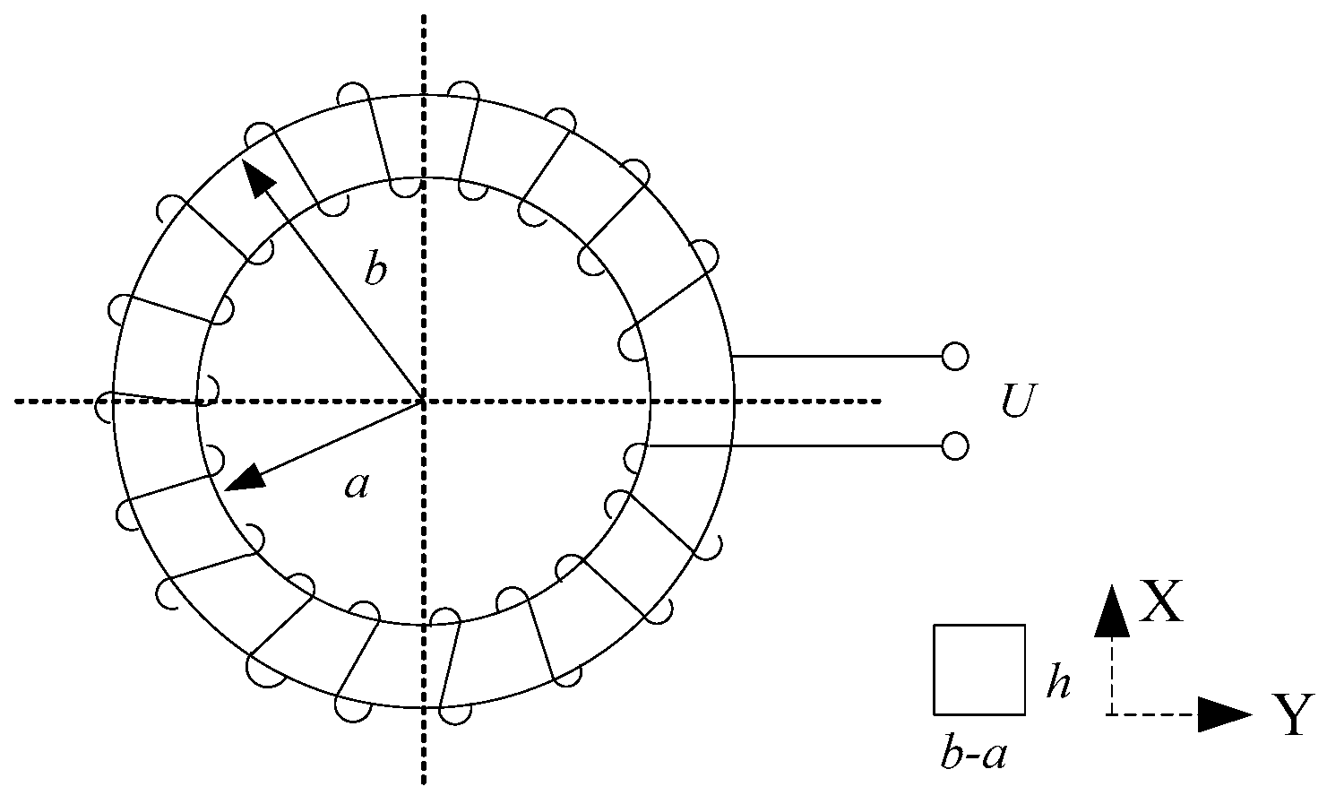
2.1. Rogowski Coil
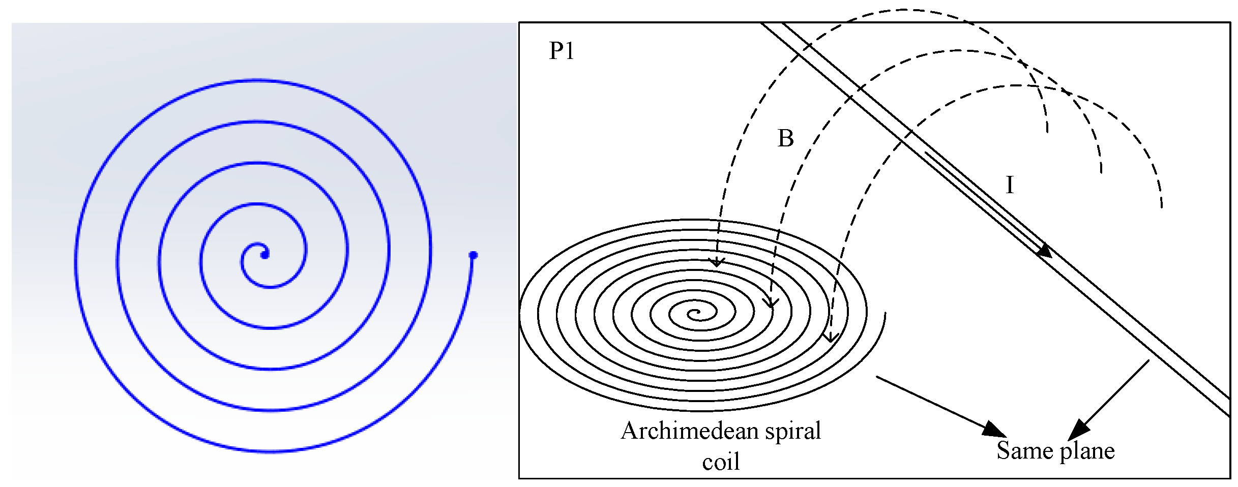
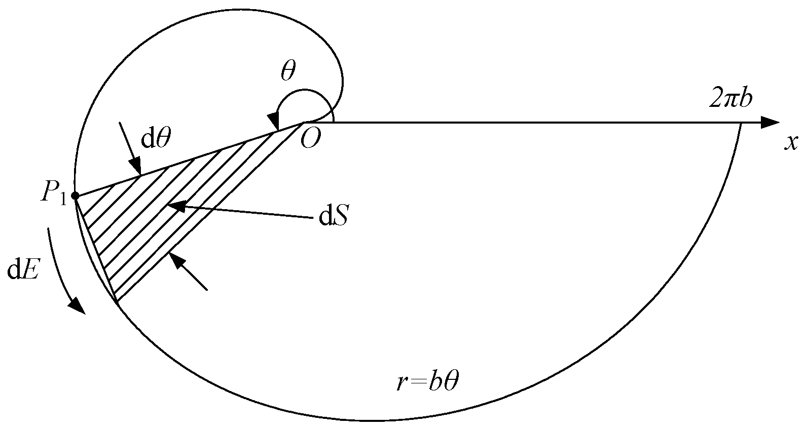
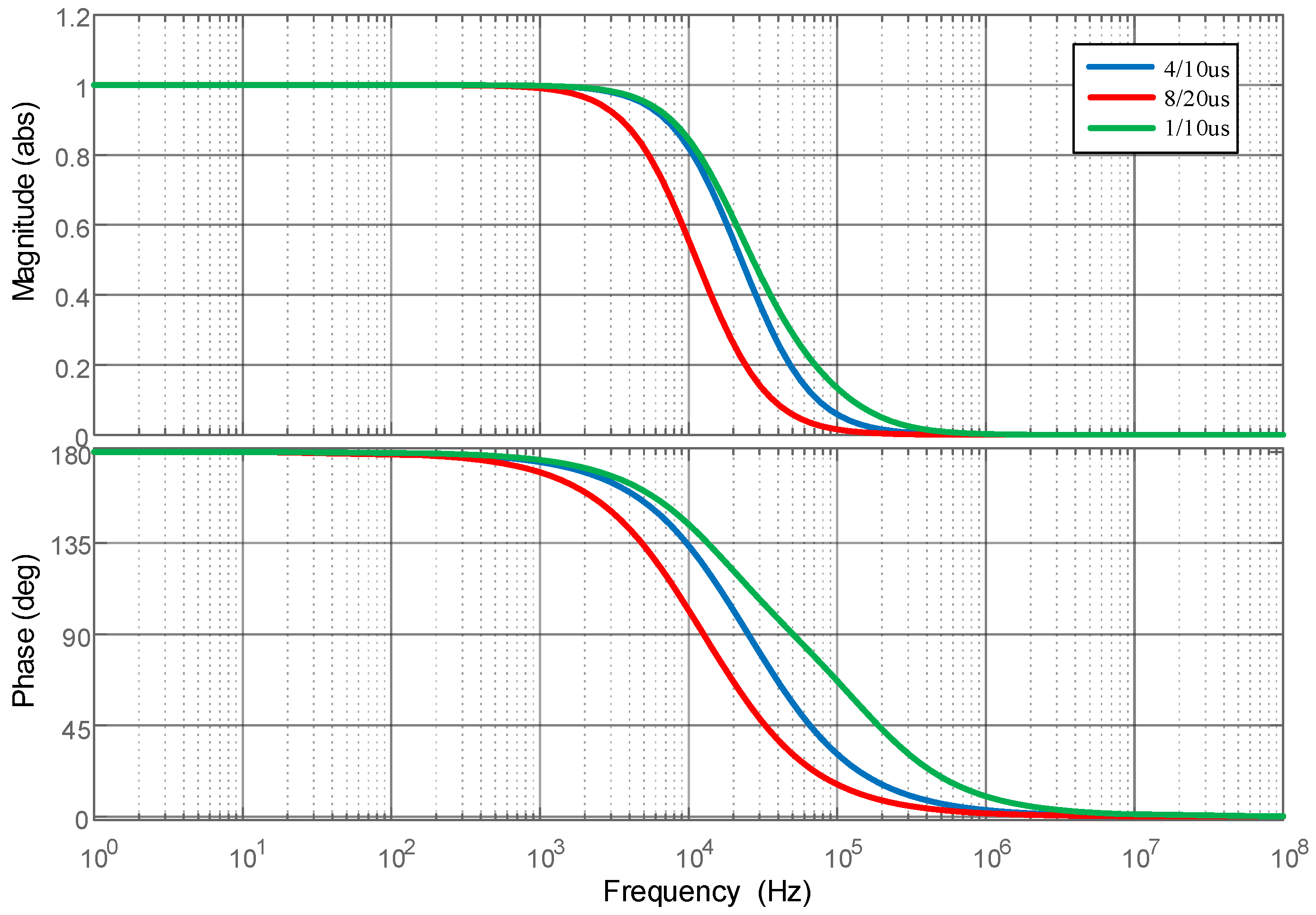
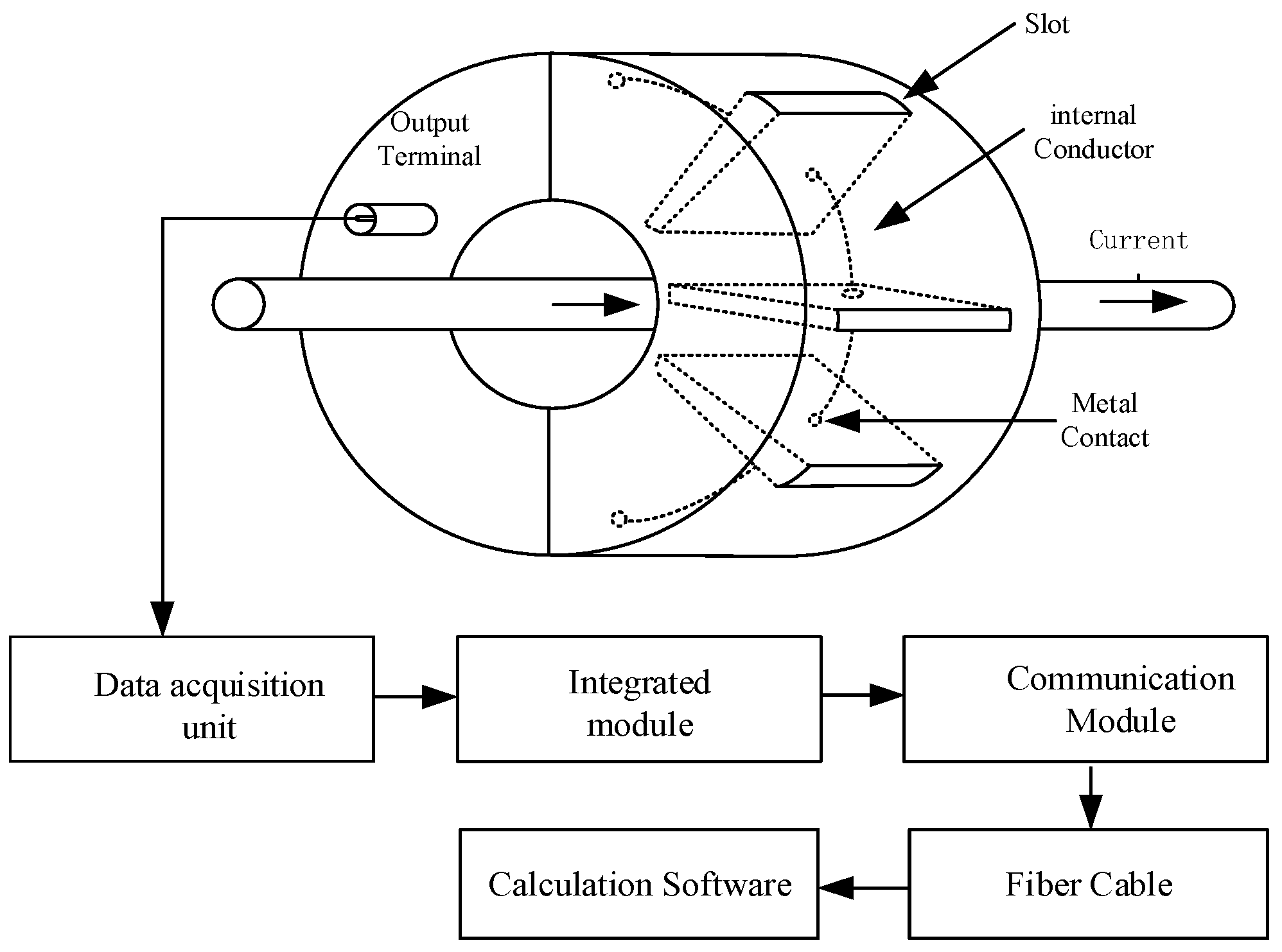
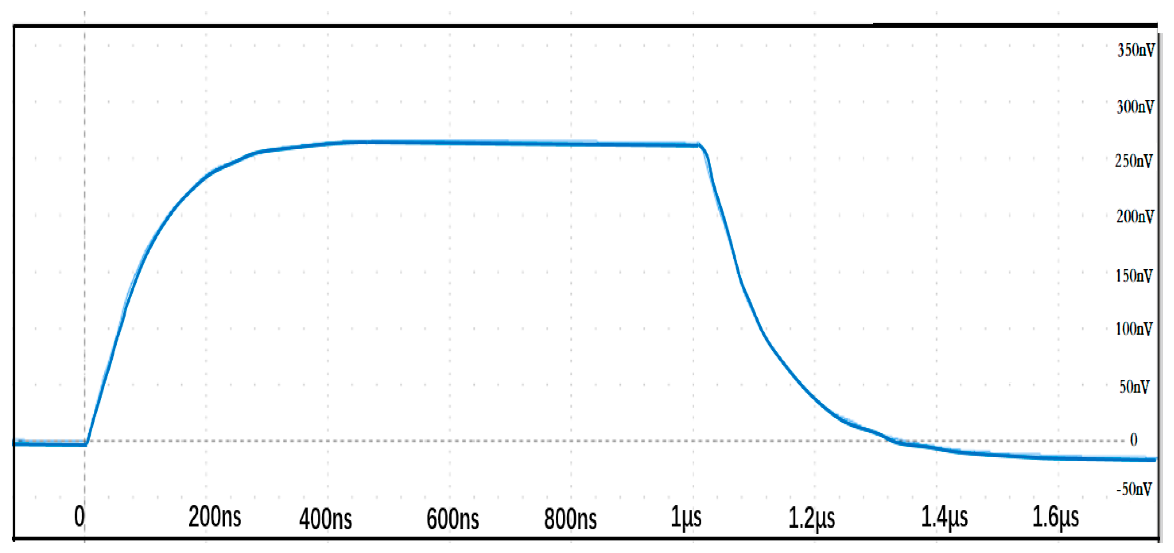
2.2. Magnetic Field Sensor
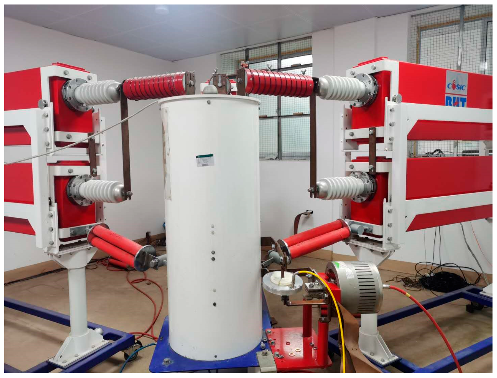
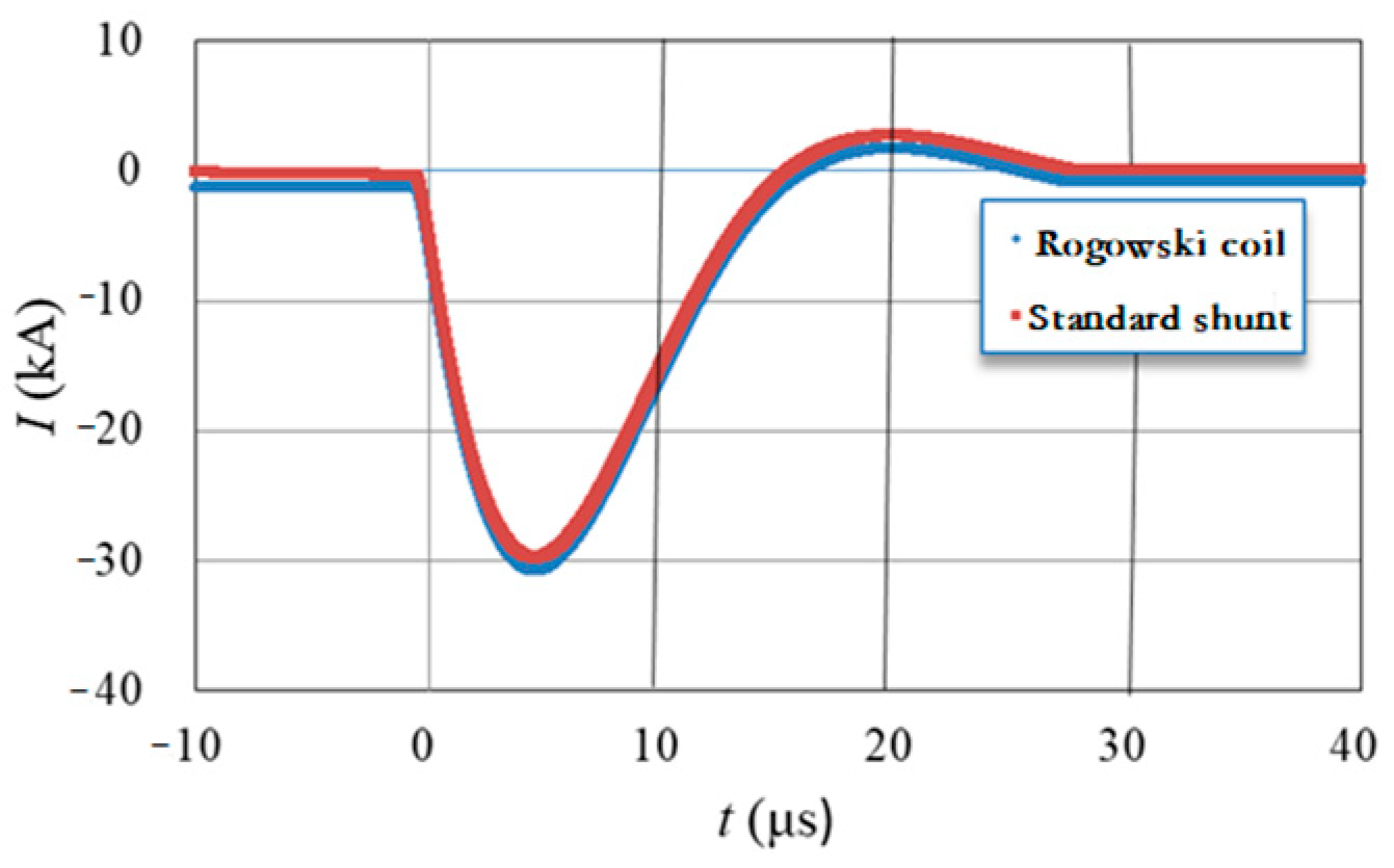
3. 100 kA Lightning Impulse Current Test
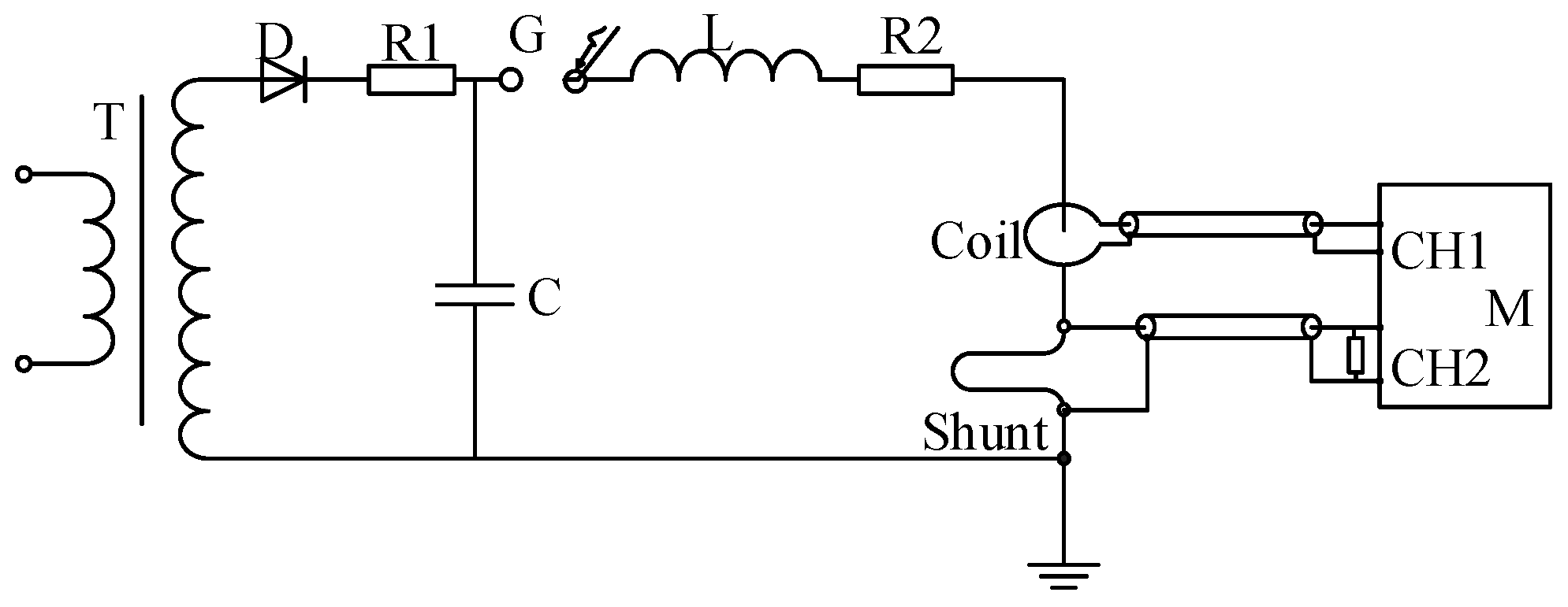
3.1. Test of Rigid Rogowski Coil
3.2. Test of Magnetic Field Sensor
4. Conclusions
Author Contributions
Funding
Institutional Review Board Statement
Informed Consent Statement
Data Availability Statement
Conflicts of Interest
References
- Destefan, D.E. Calibration and testing facility for resistance welding current monitors. IEEE Trans. Instrum. Meas. 1996, 45, 453–456. [Google Scholar] [CrossRef]
- Ziegler, S.; Woodward, R.C.; Iu, H.H.; Borle, L.J. Current Sensing Techniques: A Review. IEEE Sens. J. 2009, 9, 354–376. [Google Scholar] [CrossRef]
- Yao, X.; Chen, J.; Sun, W. Experimental study on measuring error in impulse current system. High Volt. Eng. 2006, 32, 12–15. [Google Scholar]
- Yuan, Y.; Ren, W.; Wang, A.; Jiang, N.; Li, H. Study on calibration of impulse current measuring system. High Volt. Appar. 2015, 51, 102–106. [Google Scholar]
- Zou, J.; Duan, X.; Zhang, T. The simulating calculation and experimental research of Rogowski coil for current measurement. Trans. China Electrotech. Soc. 2001, 16, 81–84. [Google Scholar]
- Liu, J.; Xu, Q.; Li, S.; Yin, Y.; Feng, J.; Zhou, X. Fold Band Shunt Used in measuring the ns-grade pulse current. High Volt. Eng. 2006, 32, 57–59. [Google Scholar]
- Yu, C.; Yu, D.; He, J. Analysis of step response of plate-shunt. J. Xi’an Jiao Tong Univ. 1991, 25, 65–72. [Google Scholar]
- Fang, H. Low-inductance shunt for high impulse current measurement. High Volt. Appratus 1982, 18, 18–24. [Google Scholar]
- Gerasimov, A. Wide-range inductive sensors of currents with nanosecond rise times for measuring parameters of high-current pulses (Review). Instrum. Exp. Tech. 2002, 45, 147–161. [Google Scholar] [CrossRef]
- Jun, Y.; Liu, H.; Yang, G.; Ling, G. Design of a Flexible Rogowski Coil with Active integrator Applied in Lightning Current Collection. In Proceedings of the 2016 33rd International Conference on Lightning Protection (ICLP), Estoril, Portugal, 25–30 September 2016. [Google Scholar]
- Metwally, I.A. Self-Integrating Rogowski coil for high-impulse current measurement. IEEE Trans. Instrum. Meas. 2010, 59, 353–360. [Google Scholar] [CrossRef]
- IEC Standard 62475; High-Current Test Techniques—Definitions and Requirements for Test Currents and Measuring Systems. IEC: Geneva, Switzerland, 2010.
- Istrate, D.; Blanc, I.; Fortuné, D. Development of a Measurement Setup for High Impulse Currents. IEEE Trans. Instrum. Meas. 2013, 62, 1473–1478. [Google Scholar] [CrossRef]
- Chiampi, M.; Crotti, G.; Morando, A. Evaluation of flexible Rogowski Coil performances in power frequency applications. IEEE Trans. Instrum. Meas. 2011, 60, 854–862. [Google Scholar] [CrossRef]
- Nurmansah, A.P.; Hidayat, S. Design and testing PCB Rogowski-coil current sensor for high current application. In Proceedings of the 2017 International Conference on High Voltage Engineering and Power Systems (ICHVEPS), Bali, Indonesia, 2–5 October 2017. [Google Scholar]
- IEEE PSRC Special Report. Practical Aspects of Rogowski Coil Applications to Relaying. September 2010, pp. 1–72. Available online: https://www.pes-psrc.org/kb/report/034.pdf (accessed on 11 June 2025).
- Chekurov, Y.; Hällström, J. Influence of busbar geometry on AC current measurement using Rogowski coil. In Proceedings of the 2008 Conference on Precision Electromagnetic Measurements Digest, Broomfield, CO, USA, 8–13 June 2008; pp. 541–543. [Google Scholar]
- Sarwade, A.N.; Katti, P.K.; Ghodekar, J.G. Use of accurate measurement of Secondary Current contaminated with CT saturation in Distance Protection Scheme. In Proceedings of the 2016 IEEE 6th International Conference on Power Systems (ICPS), New Delhi, India, 4–6 March 2016. [Google Scholar]
- Texas Instrument Design. Active Integrator for Rogowski Coil Reference Design with Improved Accuracy for Relays and Breakers” TIDUBY4A–April 2016–Revised September 2016. Available online: https://www.ti.com/tool/TIDA-00777 (accessed on 11 June 2025).
- Sanchez, J.; Ramirez, D.; Ravelo, S.I.; Lopes, A.; Cardoso, S.; Ferreira, R.; Freitas, P.P. Electrical Characterization of a Magnetic Tunnel Junction Current Sensor for Industrial Applications. IEEE Trans. Magn. 2012, 48, 2823–2826. [Google Scholar] [CrossRef]
- Marcellis, A.D.; Cubells-Beltran, M.D.; Reig, C.; Madrenas, J.; Zadov, B.; Paperno, E.; Cardoso, S.; Freitas, P.P. Quasi-digital front-ends for current measurement in integrated circuits with giant magnetoresistance technology. IET Circuits Devices Syst. 2014, 8, 291–300. [Google Scholar] [CrossRef]
- Poon, T.Y.; Tse, N.C.F.; Lau, R.W.H. Extending the GMR Current Measurement Range with a Counteracting Magnetic Field. Sensors 2013, 13, 8042–8059. [Google Scholar] [CrossRef] [PubMed]
- Li, Z.; Zhang, S.; Wu, Z.; Abu-Siada, A.; Tao, Y. Study of Current Measurement Method Based on Circular Magnetic Field Sensing Array. Sensors 2018, 18, 1439. [Google Scholar] [CrossRef] [PubMed]
- Ripka, P.; Kejik, P.; Kaspar, P.; Draxler, K. Precise DC current sensors. In Proceedings of the IEEE Instrumentation and Measurement Technology Conference and IMEKO Tec, Brussels, Belgium, 1 February 1996; pp. 1479–1483. [Google Scholar]
- Karvan, K.; Bhargab, D. Polymer transduction cavity based optical fiber Fabry—Perot interferometer for VOC sensing. Results Opt. 2023, 12, 100479. [Google Scholar]
- Gong, Z.; Xiang, Z.; OuYang, X.; Zhang, J.; Lau, N.; Zhou, J.; Chan, C.C. Wearable Fiber Optic Technology Based on Smart Textile: A Review. Materials 2019, 12, 3311. [Google Scholar] [CrossRef] [PubMed]
- Yerin, C.V.; Vivchar, V.I. Ellipsometry of magnetic fluid in a magnetic field. J. Magn. Magn. Mater. 2020, 49, 166144. [Google Scholar] [CrossRef]
- Draxler, K.; Styblikova, R. Magnetic shielding of Rogowski coils. IEEE Trans. Instrum. Meas. 2018, 67, 1207–1213. [Google Scholar] [CrossRef]
- Kyriazis, G.A. The effectiveness of current-comparator magnetic shields against leakage fields at power frequencies. In Proceedings of the Conference Digest Conference on Precision Electromagnetic Measurements, Ottawa, ON, Canada, 16–21 June 2002; pp. 34–35. [Google Scholar]


| Coil Parameters | Value | Coil Parameters | Value |
|---|---|---|---|
| Self-inductance | 3.04 μH | Distributed capacitance | 2.32 (nF) |
| Low-frequency cutoff Frequency | 80 Hz | High-frequency cutoff Frequency | 1.8 (MHz) |
| Sensitivity | 1.253 (V/kA) | Rise time | 120 (ns) |
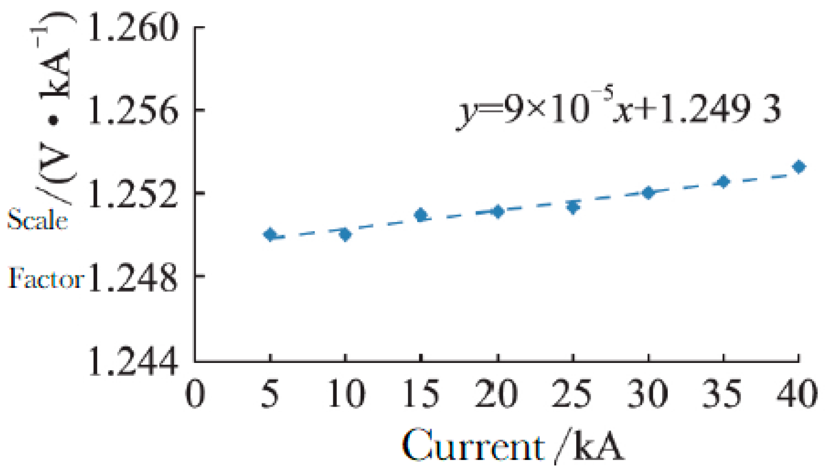
| Standard Current (kA) | Measured Current (kA) | Calibrated Scale Factor k1 (V/A) | Scale Factor of Fitting Curve k2 (V/A) | Relative Deviation (%) |
|---|---|---|---|---|
| 49,624.1 | 49,632.0 | 1.2532 | 1.2529 | −0.02 |
| 59,809.3 | 59,852.3 | 1.2539 | 1.2538 | 0.02 |
| 69,742.3 | 69,825.8 | 1.2545 | 1.2547 | 0.02 |
| 79,856.3 | 80,034.7 | 1.2558 | 1.2556 | −0.02 |
| 89,769.2 | 89,998.5 | 1.2562 | 1.2565 | −0.02 |
| 95,280.3 | 95,576.9 | 1.2569 | 1.2574 | −0.02 |
| 49,624.1 | 49,818.2 | 1.2579 | 1.2583 | −0.04 |
| Measurement Uncertainty Components | Parameter | Measurement Uncertainty Components | Parameter |
|---|---|---|---|
| Introduced by measurement repeatability uA | 0.0002 | Introduced by the short-term stability uB3 | 0.00063 |
| Introduced by the standard measuring device uB1 | 0.002 | Introduced by long-term stability uB4 | 0.001 |
| Introduced by the linearity of the Rogowski coil’s scale factor uB2 | 0.001 | / | / |
| Combined standard measurement uncertainty | 2.53 × 10⁻³ | Expanded measurement uncertainty (k = 2) | Urel = 0.52% |
Disclaimer/Publisher’s Note: The statements, opinions and data contained in all publications are solely those of the individual author(s) and contributor(s) and not of MDPI and/or the editor(s). MDPI and/or the editor(s) disclaim responsibility for any injury to people or property resulting from any ideas, methods, instructions or products referred to in the content. |
© 2025 by the authors. Licensee MDPI, Basel, Switzerland. This article is an open access article distributed under the terms and conditions of the Creative Commons Attribution (CC BY) license (https://creativecommons.org/licenses/by/4.0/).
Share and Cite
Li, W.; Diao, Y.; Zhou, F.; Long, Z.; Xie, S.; Fan, J.; Hu, K.; Wang, Z. Current Sensor with Optimized Linearity for Lightning Impulse Current Measurement. Sensors 2025, 25, 4516. https://doi.org/10.3390/s25144516
Li W, Diao Y, Zhou F, Long Z, Xie S, Fan J, Hu K, Wang Z. Current Sensor with Optimized Linearity for Lightning Impulse Current Measurement. Sensors. 2025; 25(14):4516. https://doi.org/10.3390/s25144516
Chicago/Turabian StyleLi, Wenting, Yinglong Diao, Feng Zhou, Zhaozhi Long, Shijun Xie, Jiawei Fan, Kangmin Hu, and Zhehao Wang. 2025. "Current Sensor with Optimized Linearity for Lightning Impulse Current Measurement" Sensors 25, no. 14: 4516. https://doi.org/10.3390/s25144516
APA StyleLi, W., Diao, Y., Zhou, F., Long, Z., Xie, S., Fan, J., Hu, K., & Wang, Z. (2025). Current Sensor with Optimized Linearity for Lightning Impulse Current Measurement. Sensors, 25(14), 4516. https://doi.org/10.3390/s25144516