
A Review on UAS Trajectory Estimation Using Decentralized Multi-Sensor Systems Based on Robotic Total Stations

 , , and
Abstract
1. Introduction

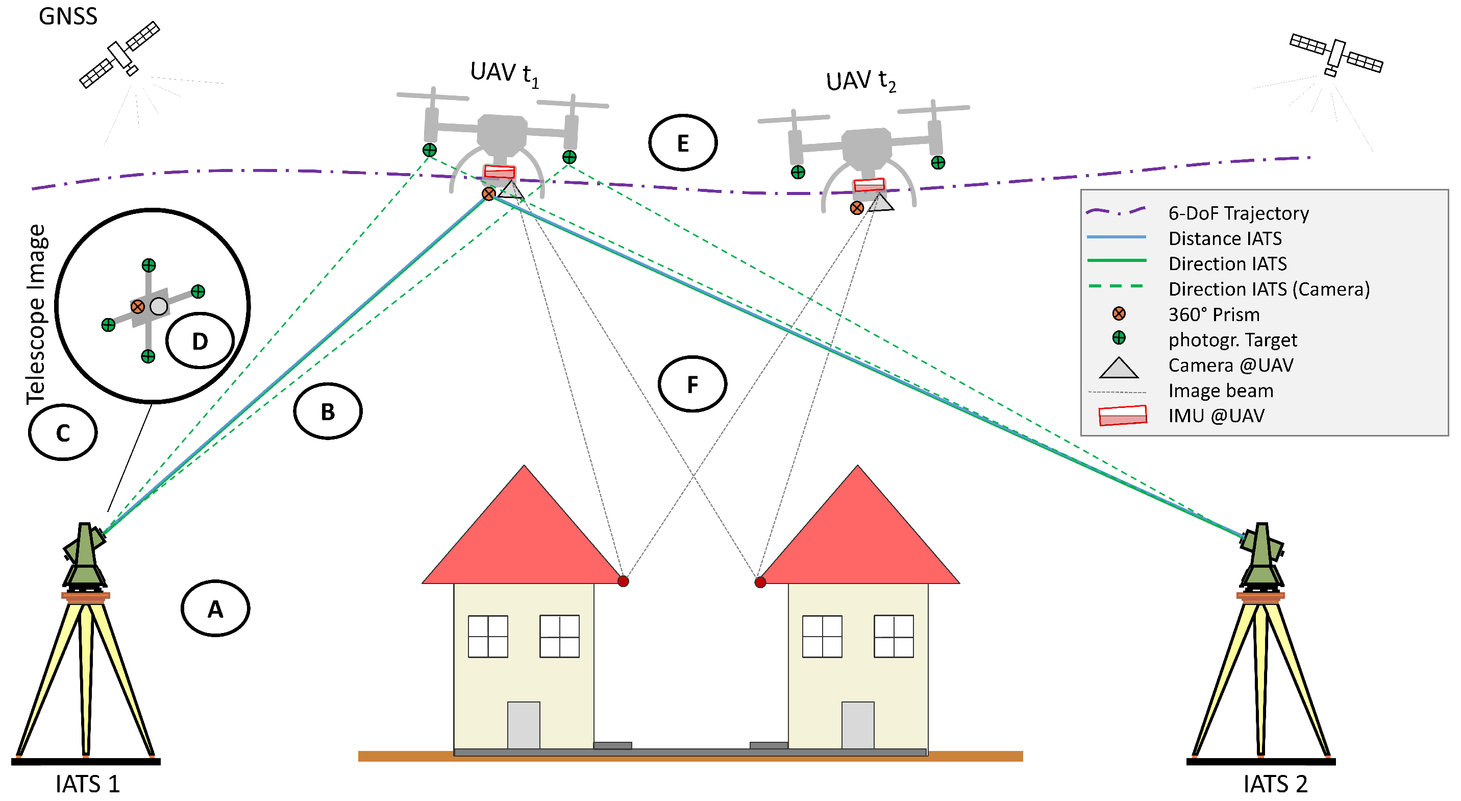
| Group | Publications | Main Contribution to a Decentralized Multi-Sensor System |
|---|---|---|
| A | Thalmann and Neuner [5], Kälin et al. [6], Grimm and Hornung [7], Stempfhuber and Sukale [8] | Time synchronization and latency estimation of RTS and uncertainty assessment of RTS for kinematic measurement scenarios |
| B | Brocks [9], Kukuvec [10], Hirt et al. [11] | Investigation of uncertainties introduced by atmospheric refraction on RTS measurements |
| C | Hauth et al. [12], Ehrhart [13], Wagner et al. [14] | Investigation of the capabilities of IATS and image evaluation in combination with RTS measurements |
| D | Niemeyer et al. [15] | Functional model and simulation regarding the orientation estimation of a UAS based on image observations from IATS |
| E | Thalmann and Neuner [16] | Robust Kalman Filter for fusion of RTS and IMU data |
| F | Skaloud and Lichti [2], Brun et al. [17], Pöppl et al. [18] | Holistic trajectory estimation framework that uses correspondences derived from mapping sensors, e.g., laser scanning, to optimize the trajectory |
2. Measurement Process of RTS
2.1. Atmospheric Effects
2.2. Systematic Deviations of 360° Prisms
2.3. Kinematic Measurements of UAS with RTS
2.4. Current State of the RTS Measurement Process in the Context of UAS Trajectory Estimation
3. Time Synchronization of RTS
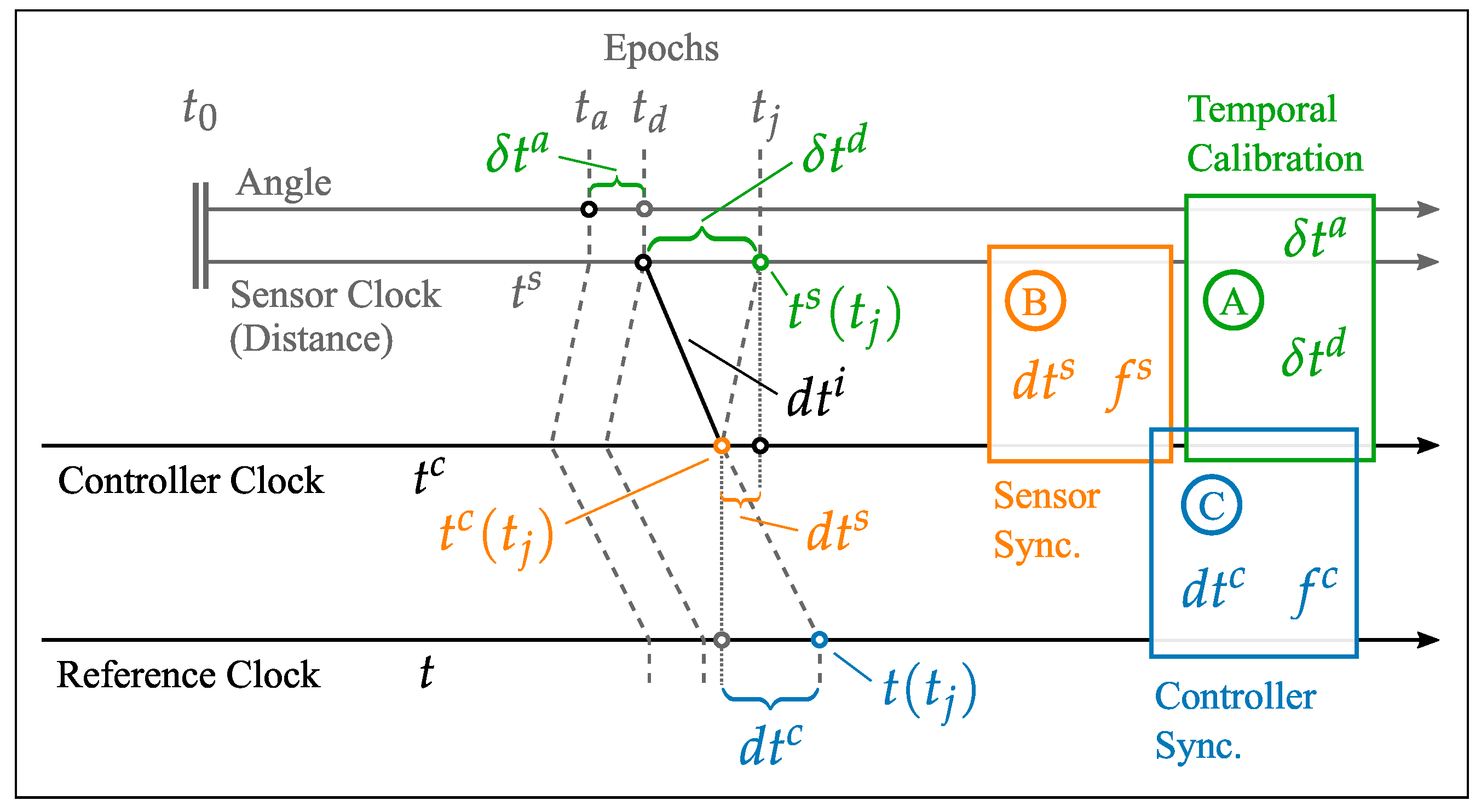
3.1. Temporal Calibration of RTS
- Controller Synchronization: Estimation of the temporal offset and the frequency error between the external controller and a time reference.
- Sensor Synchronization: Estimation of the temporal offset and frequency error between the time-referenced controller and the sensor board of the RTS, which combines the measurement data of the individual submodules.
- Temporal Calibration: The final step focuses on estimating the intrinsic and extrinsic latency (which includes the interface latency ) of the RTS, using the reference sensor (robotic arm).
- The effect of controller synchronization using NTP contributes about 40 μs to the overall uncertainty.
- The uncertainty associated with sensor board synchronization is approximately 70 μs.
- The uncertainty of extrinsic latency, denoted as , adds around 80 μs to the total uncertainty.
3.2. Recent Work on Time Synchronization of RTS in the Context of Kinematic Measurements
3.3. Current State of Time Synchronization for RTS
4. Image-Based Total Station Measurements
5. Integrated Trajectory Estimation
6. Conclusions and Outlook
Author Contributions
Funding
Acknowledgments
Conflicts of Interest
References
- Dreier, A.; Janßen, J.; Kuhlmann, H.; Klingbeil, L. Quality Analysis of Direct Georeferencing in Aspects of Absolute Accuracy and Precision for a UAV-Based Laser Scanning System. Remote Sens. 2021, 13, 3564. [Google Scholar] [CrossRef]
- Skaloud, J.; Lichti, D. Rigorous approach to bore-sight self-calibration in airborne laser scanning. ISPRS J. Photogramm. Remote Sens. 2006, 61, 47–59. [Google Scholar] [CrossRef]
- Pöppl, F.; Neuner, H.; Mandlburger, G.; Pfeifer, N. Integrated trajectory estimation for 3D kinematic mapping with GNSS, INS and imaging sensors: A framework and review. ISPRS J. Photogramm. Remote Sens. 2023, 196, 287–305. [Google Scholar] [CrossRef]
- Subirana, J.S.; Zornoza, J.J.; Hernández-Pajares, M. Time References in GNSS. 2011. Available online: https://gssc.esa.int/navipedia/index.php/Time_References_in_GNSS (accessed on 15 May 2025).
- Thalmann, T.; Neuner, H. Temporal calibration and synchronization of robotic total stations for kinematic multi-sensor-systems. J. Appl. Geod. 2021, 15, 13–30. [Google Scholar] [CrossRef]
- Kälin, U.; Staffa, L.; Grimm, D.E.; Wendt, A. Highly Accurate Pose Estimation as a Reference for Autonomous Vehicles in Near-Range Scenarios. Remote Sens. 2022, 14, 90. [Google Scholar] [CrossRef]
- Grimm, D.; Hornung, U. Leica ATRplus–Leistungssteigerung der automatischen Messung und Verfolgung von Prismen. In AVN—Allgemeine Vermessungsnachrichten; VDE VERLAG GmbH: Berlin, Germany, 2015; pp. 269–276. [Google Scholar]
- Stempfhuber, W.; Sukale, J. Kinematische Leistungsfähigkeit der Multistation Leica MS60. Geomatik Schweiz. 2017. Available online: https://geomatik.ch/ (accessed on 13 May 2025).
- Brocks, K. The curvature of rays of light near the earth’s surface: Tabellen des Refraktionskoeffizienten, I. Teil (Bereich des Präzisionsnivellements). Dtsch. Hydrogr. Z. 1950, 3, 241–248. [Google Scholar] [CrossRef]
- Kukuvec, A. Vertikaler Refraktionseffekt—Messung und Effekt. Master’s Thesis, TU Graz, Graz, Austria, 2010. [Google Scholar]
- Hirt, C.; Guillaume, S.; Wisbar, A.; Bürki, B.; Sternberg, H. Monitoring of the refraction coefficient in the lower atmosphere using a controlled setup of simultaneous reciprocal vertical angle measurements. J. Geophy. Res. Atmos. 2010, 115. [Google Scholar] [CrossRef]
- Hauth, S.; Schlüter, M.; Thiery, F. Schneller und ausdauernder als das menschliche Auge: Modulare Okularkameras am Motortachymeter. Allg. Vermess. 2013, 6/2013, 210–216. [Google Scholar]
- Ehrhart, M. Applications of Image-Assisted Total Stations: Concepts, Experiments, Results and Calibration; Shaker Verlag: Düren, Germany, 2017. [Google Scholar]
- Wagner, A.; Wasmeier, P.; Reith, C.; Wunderlich, T. Bridge monitoring by means of video-tacheometer–A case study. Allg. Vermess. 2013, 120, 283–292. [Google Scholar]
- Niemeyer, F.; Bill, R.; Grenzdörffer, G. Konzeption und Genauigkeitsabschätzungen für eine Bestimmung der äußeren Orientierung eines Unmanned Aerial Vehicles (UAV). Photogramm. Fernerkund. Geoinform. 2012, 2012, 141–157. [Google Scholar] [CrossRef]
- Thalmann, T.; Neuner, H. Sensor fusion of robotic total station and inertial navigation system for 6DoF tracking applications. Appl. Geomat. 2024, 16, 933–949. [Google Scholar] [CrossRef]
- Brun, A.; Cucci, D.A.; Skaloud, J. Lidar point–to–point correspondences for rigorous registration of kinematic scanning in dynamic networks. ISPRS J. Photogramm. Remote Sens. 2022, 189, 185–200. [Google Scholar] [CrossRef]
- Pöppl, F.; Ullrich, A.; Mandlburger, G.; Pfeifer, N. A flexible trajectory estimation methodology for kinematic laser scanning. ISPRS J. Photogramm. Remote Sens. 2024, 215, 62–79. [Google Scholar] [CrossRef]
- Ehrhart, M.; Lienhart, W. Accurate Measurements with Image-Assisted Total Stations and Their Prerequisites. J. Surv. Eng. 2017, 143, 1–12. [Google Scholar] [CrossRef]
- Glira, P.; Pfeifer, N.; Mandlburger, G. Hybrid orientation of airborne LIDAR point clouds and aerial images. ISPRS Ann. Photogramm. Remote Sens. Spat. Inform. Sci. 2019, IV-2/W5, 567–574. [Google Scholar] [CrossRef]
- Grimm, D.; Kleemaier, G.; Zogg, H.M. ATRplus White Paper; Leica Geosystems AG: Heerbrugg, Switzerland, 2015. [Google Scholar]
- Graesser, C.; Nordenfelt, M.; Jorawsky, C. White Paper: Trimble SX12 Tracking and Target Separation. 2021. Available online: https://geospatial.trimble.com/en/resources/whitepaper/trimble-sx12-tracking-and-target-separation (accessed on 8 May 2025).
- Brunner, F. Overview of geodetic refraction studies. In Geodetic Refraction: Effects of Electromagnetic Wave Propagation Through the Atmosphere; Springer: Berlin/Heidelberg, Germany, 1984; pp. 1–6. [Google Scholar]
- Möser, M.; Hoffmeister, H.; Müller, G.; Staiger, R.; Wanninger, L. Handbuch Ingenieurgeodaesie: Grundlagen, 4th ed.; Wichmann: Berlin, Germany, 2012. [Google Scholar]
- Bomford, G. Geodesy, 4th ed.; Clarendon: Oxford, UK, 1980. [Google Scholar]
- Wunderlich, T. Die Voraussetzungsfreie Bestimmung von Refraktionswinkeln; Technische Universität Wien: Vienna, Austria, 1985; Volume 26. [Google Scholar]
- Zhou, J.; Shi, B.; Liu, G.; Ju, S. Accuracy analysis of dam deformation monitoring and correction of refraction with robotic total station. PLoS ONE 2021, 16, e0251281. [Google Scholar] [CrossRef] [PubMed]
- Hennes, M. Zum Refraktionseinfluss auf terrestrische geodätische Messungen im Kontext der Messtechnik und der Instrumentenentwicklung. FuB-Flächenmanag. Bodenordn. 2002, 64, 73–86. [Google Scholar] [CrossRef]
- Eschelbach, C. Refraktionskorrekturbestimmung durch Modellierung des Impuls- und Wärmeflusses in der Rauhigkeitsschicht. PhD Thesis, Karlsruher Institut für Technologie, Karlsruhe, Germany, 2009. [Google Scholar] [CrossRef]
- Reiterer, A. Modeling Atmospheric Refraction Influences by Optical Turbulences Using an Image-Assisted Total Station. 2012. Available online: https://geodaesie.info/images/zfv/137-jahrgang-2012/downloads/zfv_2012_3_Reiterer.pdf (accessed on 4 May 2025).
- Favre, C.; Hennes, M. Zum Einfluss der geometrischen Ausrichtung von 360°-Reflektoren bei Messungen mit automatischer Zielerfassung. Mensurat. Photogramm. Genie Rural 2000, 98, 72–78. [Google Scholar]
- Lackner, S.; Lienhart, W. Impact of prism type and prism orientation on the accuracy of automated total station measurements. In Proceedings of the 3rd Joint International Symposium on Deformation Monitoring, Vienna, Austria, 30 March–1 April 2016. [Google Scholar]
- Stempfhuber, W. Ein Integritätswahrendes Messsystem für Kinematische Anwendungen. Ph.D. Thesis, Technische Universität München, München, Germany, 2004. [Google Scholar]
- Keller, F.; Kagerah, S.; Sternberg, H. Automatisierung eines Low-Cost-360° Reflektors für die genaue Positionierung einer 3D-Trajektorie. In AVN—Allgemeine Vermessungsnachrichten; VDE VERLAG GmbH: Berlin, Germany, 2015; pp. 259–268. [Google Scholar]
- Leica Geosystems AG. Leica MS60/TS60 User Manual. 2016. Available online: https://naic.nrao.edu/arecibo/phil/hardware/theodolites/ms60_ts60_usersManual_leica.pdf (accessed on 16 May 2025).
- Kälin, U.; Hürzeler, M.; Grimm, D. Calibration of Kinematic Measuring Systems. Ingenieurvermessung 23. Beiträge zum 20. Internationalen Ingenieurvermessungskurs Zürich, 2023; Wichmann: Berlin, Germany, 2023; pp. 195–207. [Google Scholar]
- Kerekes, G.; Schwieger, V. Possibilities and Limitations in the extrinsic Synchronization of Observations from Networks of Robotic Total Stations. In Proceedings of the FIG Working Week 2024, Accra, Ghana, 19–24 May 2024. [Google Scholar]
- Stempfhuber, W. Verification of the Trimble universal total station (UTS) performance for kinematic applications. Optical 3-D Measurement Techniques: Applications in GIS, Mobile Mapping, Manufacturing, Quality Control, Robotics, Navigation, Cultural Heritage, Natural and Manmade Hazards Monitoring, Medical Imaging, VR Generation and Animation. In Proceedings of the Conference on Optical 3-D Measurement Techniques 2009, Vienna, Austria, 1–3 July 2009; pp. 1–211. [Google Scholar]
- Vogel, S.; van der Linde, M.; Hake, F. Development and Validation of an External GPS Time Synchronization for Robotic Total Station Control. In Ingenieurvermessung 23. Beiträge zum 20. Internationalen Ingenieurvermessungskurs Zürich; Wichmann: Berlin, Germany, 2023; pp. 181–194. [Google Scholar]
- Brandstätter, M.; Mikschi, M.; Gabela, J.; Linzer, F.; Neuner, H. Uncertainty Assessment of Poses Derived from Automatic Point Cloud Registration in the Context of Stop-and-Go Multi Sensor Robotic Systems. In Proceedings of the 2024 IEEE International Conference on Multisensor Fusion and Integration for Intelligent Systems (MFI), Pilsen, Czechia, 4–6 September 2024; pp. 1–7. [Google Scholar]
- Hesse, C.; Holste, K.; Neumann, I.; Esser, R.; Geist, M. 3D HydroMapper–Ein innovatives Messsystem für die Erfassung, Prüfung und das Management von Wasser-Infrastrukturbauwerken. ZfV-Z. Geodäsie Geoinform. Landmanag. 2021, 4/2021. [Google Scholar] [CrossRef]
- Liu, Y.; Noguchi, N. Development of an unmanned surface vehicle for autonomous navigation in a paddy field. Eng. Agric. Environ. Food 2016, 9, 21–26. [Google Scholar] [CrossRef]
- Vaidis, M.; Giguère, P.; Pomerleau, F.; Kubelka, V. Accurate outdoor ground truth based on total stations. In Proceedings of the 2021 18th Conference on Robots and Vision (CRV), Burnaby, BC, Canada, 26–28 May 2021; pp. 1–8. [Google Scholar] [CrossRef]
- Vaidis, M.; Dubois, W.; Daum, E.; LaRocque, D.; Pomerleau, F. Uncertainty Analysis for Accurate Ground Truth Trajectories with Robotic Total Stations. In Proceedings of the 2023 IEEE/RSJ International Conference on Intelligent Robots and Systems (IROS), Detroit, MI, USA, 1–5 October 2023. [Google Scholar] [CrossRef]
- Pan, Y. Measuring Drone Trajectory Using Total Station with Visual Tracking. 2021. Available online: https://ethz.ch/content/dam/ethz/special-interest/baug/igp/photogrammetry-remote-sensing-dam/documents/pdf/Student_Theses/IPA_YuePan.pdf (accessed on 20 April 2025).
- Gojcic, Z.; Kalenjuk, S.; Lienhart, W. Synchronization routine for real-time synchronization of robotic total stations. In Proceedings of the INGEO 2017 7th International Conference on Engineering Surveying, Lisbon, Portugal, 18–20 October 2017; pp. 183–191. [Google Scholar]
- Roberts, C.; Boorer, P. Kinematic positioning using a robotic total station as applied to small-scale UAVs. J. Spat. Sci. 2016, 61, 29–45. [Google Scholar] [CrossRef]
- Maxim, A.; Lerke, O.; Prado, M.; Dörstelmann, M.; Menges, A.; Schwieger, V. UAV Guidance with Robotic Total Station for Architectural Fabrication Processes. In Unmanned Aerial Vehicles; Wißner-Verlag Augsburg: Augsburg, Germany, 2017; DVW-Schriftenreihe; Volume 86, pp. 145–161. [Google Scholar]
- Merkle, D.; Reiterer, A. Automated Method for SLAM Evaluation in GNSS-Denied Areas. Remote Sens. 2023, 15, 5141. [Google Scholar] [CrossRef]
- Paraforos, D.S.; Sharipov, G.M.; Heiß, A.; Griepentrog, H.W. Position Accuracy Assessment of a UAV-Mounted Sequoia+ Multispectral Camera Using a Robotic Total Station. Agriculture 2022, 12, 885. [Google Scholar] [CrossRef]
- Vougioukas, S.G.; He, L.; Arikapudi, R. Orchard worker localisation relative to a vehicle using radio ranging and trilateration. Biosyst. Eng. 2016, 147, 1–16. [Google Scholar] [CrossRef]
- Vroegindeweij, B.A.; IJsselmuiden, J.; van Henten, E.J. Probabilistic localisation in repetitive environments: Estimating a robot’s position in an aviary poultry house. Comput. Electron. Agric. 2016, 124, 303–317. [Google Scholar] [CrossRef]
- Paraforos, D.S.; Reutemann, M.; Sharipov, G.; Werner, R.; Griepentrog, H.W. In-field position accuracy at the millimetre level using a total station: Validation using an industrial robotic arm. In Proceedings of the 6th International Conference on Machine Control & Guidance, Berlin, Germany, 1–2 October 2018; pp. 44–51. [Google Scholar]
- Tombrink, G.; Dreier, A.; Klingbeil, L.; Kuhlmann, H. Trajectory evaluation using repeated rail-bound measurements. J. Appl. Geod. 2023, 17, 205–216. [Google Scholar] [CrossRef]
- Tombrink, G.; Dreier, A.; Klingbeil, L.; Kuhlmann, H. Spatio-temporal trajectory alignment for trajectory evaluation. J. Appl. Geod. 2025, 19, 321–331. [Google Scholar] [CrossRef]
- Bláha, M.; Eisenbeiss, H.; Grimm, D.; Limpach, P. Direct georeferencing of UAVs. Int. Arch. Photogramm. Remote Sens. Spat. Inf. Sci. 2012, 38, 131–136. [Google Scholar] [CrossRef]
- Kohoutek, T.K.; Eisenbeiss, H. Processing of UAV based range imaging data to generate detailed elevation models of complex natural structures. Int. Arch. Photogramm. Remote Sens. Spat. Inf. Sci. 2012, 39, 405–410. [Google Scholar] [CrossRef]
- Kleemaier, G. Multisensorsystem Totalstation. In MST 2018–Multisensortechnologie: Low-Cost Sensoren im Verbund; Wißner-Verlag Augsburg: Augsburg, Germany, 2018; DVW-Schriftenreihe; Volume 92, pp. 25–36. Available online: https://geodaesie.info/images/schriftenreihe/downloads/DVW_92_2018_MST_2018_FINAL_180911.pdf (accessed on 24 April 2025).
- Maar, H.; Zogg, H.M. WFD—Wave Form Digitizer Technology White Paper. 2021. Available online: https://leica-geosystems.com/about-us/content-features/wave-form-digitizer-technology-white-paper (accessed on 20 April 2025).
- Depenthal, C. Entwicklung Eines Zeitreferenzierten 4-D-Kalibrier- Und Prüfsystems füR Kinematische Optische Messsysteme. 2009. Available online: https://publikationen.bibliothek.kit.edu/1000010086 (accessed on 20 April 2025).
- Thalmann, T.; Neuner, H.B. Untersuchung des Network Time Protocols für die Synchronisation von Multi-Sensor-Systemen. AVN Allg. Vermess. 2018, 125, 163–174. [Google Scholar]
- Gojcic, Z.; Kalenjuk, S.; Lienhart, W. A routine for time-synchronization of robotic total stations. AVN—Allg. Vermess. 2018, 125, 299–307. [Google Scholar]
- Kerekes, G.; Schwieger, V. Kinematic positioning in a real time robotic total station network system. In Proceedings of the 6th International Conference on Machine Control & Guidance, Berlin, Germany, 1–2 October 2018; pp. 35–43. [Google Scholar]
- Kerekes, G.; Schwieger, V. Position determination of a moving reflector in real time by robotic total station angle measurements. In Proceedings of the GeoPrevi 2018 International Symposium-Geodesy for Smart Cities, Bucharest, Romania, 29–30 October 2018. [Google Scholar]
- Bürki, B.; Guillaume, S.; Sorber, P.; Oesch, H.P. DAEDALUS: A versatile usable digital clip-on measuring system for Total Stations. In Proceedings of the 2010 International Conference on Indoor Positioning and Indoor Navigation, Zurich, Switzerland, 15–17 September 2010; pp. 1–10. [Google Scholar] [CrossRef]
- Guillaume, S.; Geiger, A.; Scaramuzza, M. Automated High Precision Optical Tracking of Aircrafts and non-cooperative Flying Objects. In Proceedings of the 29th International Technical Meeting of the Satellite Division of The Institute of Navigation (ION GNSS+ 2016), Portland, OR, USA, 12–16 September 2016; pp. 2315–2317. [Google Scholar] [CrossRef]
- Zschiesche, K. Image Assisted Total Stations for Structural Health Monitoring—A Review. Geomatics 2022, 2, 1–16. [Google Scholar] [CrossRef]
- Svanström, F.; Alonso-Fernandez, F.; Englund, C. Drone Detection and Tracking in Real-Time by Fusion of Different Sensing Modalities. Drones 2022, 6, 317. [Google Scholar] [CrossRef]
- Ehrhart, M.; Lienhart, W. Monitoring of civil engineering structures using a state-of-the-art image assisted total station. J. Appl. Geod. 2015, 9, 174–182. [Google Scholar] [CrossRef]
- Ehrhart, M.; Lienhart, W. Development and evaluation of a long range image-based monitoring system for civil engineering structures. In Structural Health Monitoring and Inspection of Advanced Materials, Aerospace, and Civil Infrastructure 2015. International Society for Optics and Photonics; SPIE: Denver, CO, USA, 2015; Volume 9437. [Google Scholar] [CrossRef]
- Lienhart, W.; Ehrhart, M.; Grick, M. High frequent total station measurements for the monitoring of bridge vibrations. J. Appl. Geod. 2017, 11, 1–8. [Google Scholar] [CrossRef]
- Groves, P. Principles of GNSS, Inertial, and Multisensor Integrated Navigation Systems; Artech House: Norwood, MA, USA, 2013. [Google Scholar]
- Pfeifer, N.; Glira, P.; Briese, C. Direct georeferencing with on board navigation components of light weight UAV platforms. Int. Arch. Photogramm. Remote Sens. Spat. Inf. Sci. 2012, 39, 487–492. [Google Scholar] [CrossRef]
- Glira, P.; Pfeifer, N.; Briese, C.; Ressl, C. Rigorous Strip Adjustment of Airborne Laserscanning Data Based on the ICP Algorithm. Isprs Ann. Photogramm. Remote Sens. Spat. Inf. Sci. 2015, II-3/W5, 73–80. [Google Scholar] [CrossRef]
- Glira, P.; Pfeifer, N.; Mandlburger, G. Rigorous Strip Adjustment of UAV-Based Laserscanning Data Including Time-Dependent Correction of Trajectory Errors. Photogramm. Eng. Remote Sens. 2016, 82, 945–954. [Google Scholar] [CrossRef]
- Weiss, J.D.; Kee, D.S. A direct performance comparison between loosely coupled and tightly coupled GPS/INS integration techniques. In Proceedings of the 51st Annual Meeting of The Institute of Navigation (1995), Colorado Springs, Colorado, 5–7 June 1995; pp. 537–544. [Google Scholar]
- Falco, G.; Pini, M.; Marucco, G. Loose and tight GNSS/INS integrations: Comparison of performance assessed in real urban scenarios. Sensors 2017, 17, 255. [Google Scholar] [CrossRef]
- Wang, Z.; Cheng, X.; Fu, J. Optimized multi-position calibration method with nonlinear scale factor for inertial measurement units. Sensors 2019, 19, 3568. [Google Scholar] [CrossRef]
- Wen, W. 3D LiDAR aided GNSS and its tightly coupled integration with INS via factor graph optimization. In Proceedings of the 33rd International Technical Meeting of the Satellite Division of the Institute of Navigation (ION GNSS+ 2020), Online, 21–25 September 2020; pp. 1649–1672. [Google Scholar] [CrossRef]
- Cucci, D.A.; Rehak, M.; Skaloud, J. Bundle adjustment with raw inertial observations in UAV applications. ISPRS J. Photogramm. Remote Sens. 2017, 130, 1–12. [Google Scholar] [CrossRef]
- Colomina, I.; Blázquez, M. A unified approach to static and dynamic modeling in photogrammetry and remote sensing. In Proceedings of the XXth ISPRS Congress, Istanbul, Turkey, 12–23 July 2004; pp. 178–183. [Google Scholar]
- Eltner, A.; Hoffmeister, D.; Kaiser, A.; Karrasch, P.; Klingbeil, L.; Stöcker, C.; Rovere, A. UAVs for the Environmental Sciences; Wissenschaftliche Buchgesellschaft: Darmstadt, Germany, 2022. [Google Scholar]
- Pöppl, F.; Ullrich, A.; Mandlburger, G.; Pfeifer, N. Precise and efficient high-frequency trajectory estimation for LiDAR georeferencing. ISPRS J. Photogramm. Remote Sens. 2025, 223, 344–361. [Google Scholar] [CrossRef]


| Publication | Adequate Reference ( cm) | Reference | Speed | Year |
|---|---|---|---|---|
| Bláha et al. [56] | No | DGNSS | Not stated | 2012 |
| Kohoutek and Eisenbeiss [57] | No | DGNSS | Hovering | 2012 |
| Roberts and Boorer [47] | No | Photogrammetry | Hovering | 2016 |
Disclaimer/Publisher’s Note: The statements, opinions and data contained in all publications are solely those of the individual author(s) and contributor(s) and not of MDPI and/or the editor(s). MDPI and/or the editor(s) disclaim responsibility for any injury to people or property resulting from any ideas, methods, instructions or products referred to in the content. |
© 2025 by the authors. Licensee MDPI, Basel, Switzerland. This article is an open access article distributed under the terms and conditions of the Creative Commons Attribution (CC BY) license (https://creativecommons.org/licenses/by/4.0/).
Share and Cite
Dammert, L.; Thalmann, T.; Monetti, D.; Neuner, H.-B.; Mandlburger, G. A Review on UAS Trajectory Estimation Using Decentralized Multi-Sensor Systems Based on Robotic Total Stations. Sensors 2025, 25, 3838. https://doi.org/10.3390/s25133838
Dammert L, Thalmann T, Monetti D, Neuner H-B, Mandlburger G. A Review on UAS Trajectory Estimation Using Decentralized Multi-Sensor Systems Based on Robotic Total Stations. Sensors. 2025; 25(13):3838. https://doi.org/10.3390/s25133838
Chicago/Turabian StyleDammert, Lucas, Tomas Thalmann, David Monetti, Hans-Berndt Neuner, and Gottfried Mandlburger. 2025. "A Review on UAS Trajectory Estimation Using Decentralized Multi-Sensor Systems Based on Robotic Total Stations" Sensors 25, no. 13: 3838. https://doi.org/10.3390/s25133838
APA StyleDammert, L., Thalmann, T., Monetti, D., Neuner, H.-B., & Mandlburger, G. (2025). A Review on UAS Trajectory Estimation Using Decentralized Multi-Sensor Systems Based on Robotic Total Stations. Sensors, 25(13), 3838. https://doi.org/10.3390/s25133838