Article

Multi-Party Verifiably Collaborative Encryption for Biomedical Signals via Singular Spectrum Analysis-Based Chaotic Filter Bank Networks

School of Information Engineering, Guangdong University of Technology, Guangzhou 511006, China
*
Author to whom correspondence should be addressed.
Sensors 2025, 25(12), 3823; https://doi.org/10.3390/s25123823
Submission received: 26 March 2025 / Revised: 1 June 2025 / Accepted: 17 June 2025 / Published: 19 June 2025

Abstract

:
This paper proposes a multi-party verifiably collaborative system for encrypting the nonlinear and the non-stationary biomedical signals captured by biomedical sensors via the singular spectrum analysis (SSA)-based chaotic networks. In particular, the raw signals are first decomposed into the multiple components by the SSA. Then, these decomposed components are fed into the chaotic filter bank networks for performing the encryption. To perform the multi-party verifiably collaborative encryption, the window length of the SSA and the total number of the layers in the chaotic network are flexibly designed to match the total number of the collaborators. The computer numerical simulation results show that our proposed system achieves a good encryption performance.

1. Introduction

The secure transmission of biosensor signals presents unique challenges in privacy-preserving telemedicine. Wearable and implantable medical devices generate continuous streams of electrophysiological data such as EEG and PPG that contain sensitive health biomarkers [1,2,3]. These IoT-enabled biosensors operate under distinctive security constraints, where ultra-low-power operation limits complex cryptographic processing capabilities, while wireless transmission exposes time-series data to potential interception. The biomedical community consequently requires robust encryption systems that can address these challenges while maintaining the integrity and privacy of biosensor signals.
Secure biomedical encryption requires cryptosystems that fulfill Shannon’s confusion–diffusion criteria [4]. Chaotic maps offer inherent advantages through their sensitive dependence on initial conditions and nonlinear transformation properties. However, conventional chaotic systems, including logistic maps [5,6,7] and cat maps [8], face practical limitations due to their constrained key spaces. Current frequency-domain approaches, including chaotic filter banks [5] and EMD-based methods [7], introduce additional vulnerabilities because their explicit frequency-domain representations create identifiable attack surfaces.
The increasing demand for of secure biosensor data sharing has necessitated the evolution of multi-party collaborative frameworks as viable alternatives to conventional trusted third-party architectures. These distributed systems enforce strict access control through cryptographic consensus mechanisms. Secure Multi-Party Computation (SMPC) [9,10,11,12] enables this privacy-preserving distributed computing paradigm through advanced cryptographic techniques. Fully Homomorphic Encryption (FHE) [13,14] has emerged as a promising solution for cross-institutional collaboration, as it maintains end-to-end privacy by supporting computations on encrypted data without requiring decryption [15]. However, the approach faced practical barriers, including substantial computational overhead and ciphertext expansion, that strain bandwidth-constrained biosensor networks. Cloud-based acceleration has significantly improved homomorphic encryption performance through hardware optimization [16,17]. While effectively addressing computational bottlenecks, these solutions require specialized infrastructure and still face the inherent challenge of ciphertext expansion in FHE systems.
Distributed storage architectures offer potential solutions to these challenges by spreading ciphertext storage across multiple parties, thereby reducing individual storage burdens. Blockchain systems [18,19] typically use AES encryption [20], which restricts decryption to single key-holders, preventing direct multi-party decryption without key-sharing protocols. Alternative cryptographic designs based on polynomial interpolation [21] has shown promise for healthcare applications [22], though they introduce their own computational complexities during decryption that scale quadratically with the number of reconstruction shares. Moreover, SMPC encounters communication overhead challenges in real-time environments.
The verifiability of cryptographic operations represents another critical requirement for effective multi-party collaboration in medical contexts. Traditional secret-sharing schemes lack built-in mechanisms for verifying decryption accuracy, creating potential vulnerabilities if ciphertexts are intentionally modified during transmission. Recent advances have proposed verifiable schemes based on polynomial interpolation [23] and demonstrated their application in multi-cloud environments [2]. Nevertheless, verifiable decryption mechanisms tailored for chaotic cryptosystems and nonlinear signal processing remain underdeveloped in current research.
To address these challenges, this paper proposes a novel multi-party verifiably collaborative system for biosensor signal encryption based on SSA and chaotic filter bank networks. Our approach implements confusion through SSA decomposition followed by polyphase filtering and multi-layer chaotic network processing. The diffusion phase leverages the dynamic properties of chaotic systems where initial conditions propagate throughout the network architecture. The system’s unique architecture inherently enables multi-party encryption with built-in verification capabilities. The remainder of this paper details our cryptosystem design, security analysis, and computational complexity, presents comprehensive simulation results, and discusses the implications of our findings for future research in secure medical data transmission.

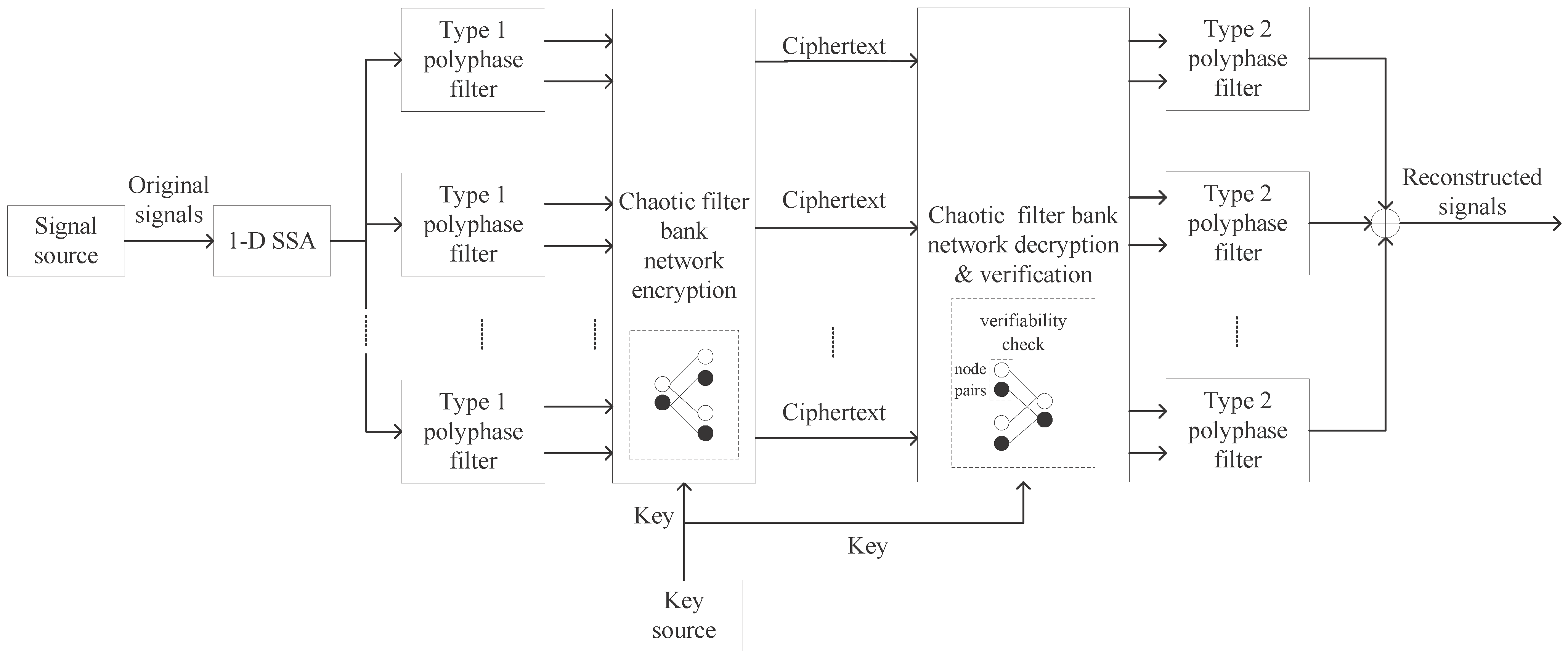
2. Proposed Cryptosystem

Figure 1 illustrates the end-to-end framework of the proposed encryption and decryption system. The decryption process is implemented as the inverse operation of the encryption algorithm. Specifically, the verification ensures data integrity by requiring consensus between two node pairs’ decryption before accepting any output of the chaotic filter bank network.

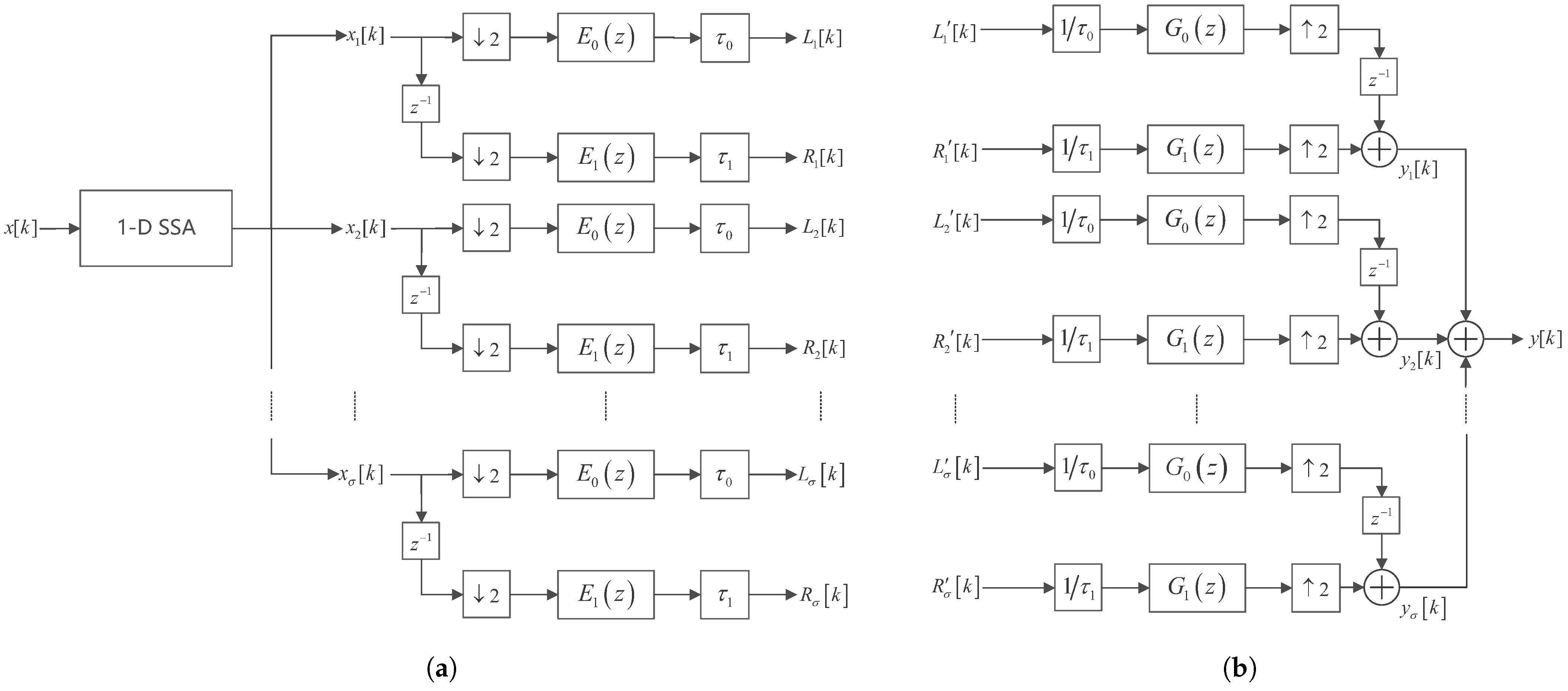
2.1. Decomposition and Reconstruction of Biosensor Signals Based on SSA and Haar Filter Bank

Figure 2a,b shows the analysis and synthesis system of the proposed method, respectively. Here, biosensor signals are decomposed by both SSA and filter bank. Let x [ k ] be a biomedical signal. Let n 1 be its length. Let σ be the total number of the nonzero singular values of the trajectory matrix X generated by x [ k ] , that is, X = i = 1 σ X i , where X i is the component matrix. These component matrices can be divided into h disjoint subsets, that is X = i = 1 h X I i , where X I i is the i th grouped matrix. For simplicity, let h = σ . For each X I i , de-Hankelization is performed to form x i k for i = 1 , 2 , , σ , where x i k is the i th singular spectral decomposition components of x k , that is, x k = i = 1 σ x i k .
Each SSA component is processed using Haar filter banks. Let L i k and R i k be the first and second subband signal of the i th SSA component decomposed by the Haar analysis filter bank [24]; L i k and R i k be the corresponding decrypted subband signals for synthesis; 2 and 2 be the 2-fold downsampler and upsampler; e i k and g i k for i = 0 , 1 be the impulse responses of the Haar analysis and synthesis filters; and τ 0 and τ 1 be the gains multiplied to the low-frequency and high-frequency subband channel, respectively. Let z 1 be a unit delay element. The output of the Haar synthesis filter bank for reconstructing the i th SSA component is denoted as y i k , and the final reconstructed signal is y k = i = 1 σ y i k .
The various signals in Figure 2 can be expressed as follows:
L i k = τ 0 m x i 2 k e 0 k m ,
R i k = τ 1 m x i 2 k 1 e 1 k m .
y i k = 1 τ 0 m L i 2 k 1 g 0 k m + 1 τ 1 m R i 2 k g 1 k m .
The type 1 polyphase matrix of the Haar analysis filter bank [5,24] and the impulse response of the Haar mother wavelet [5] are
E z = 1 1 1 1
and
ψ ( u ) = 1 0 < u < 0.5 1 0.5 < u < 1 0 otherwise .
Let G z be the type 2 polyphase matrix of the Haar synthesis filter bank. Let c = 1 and m 0 = 0 be the gain and the delay introduced by the Haar filter bank, respectively. Since the Haar filter bank achieves exact perfect reconstruction, we have E z G z = c z m 0 I , where I is an identity matrix [25].

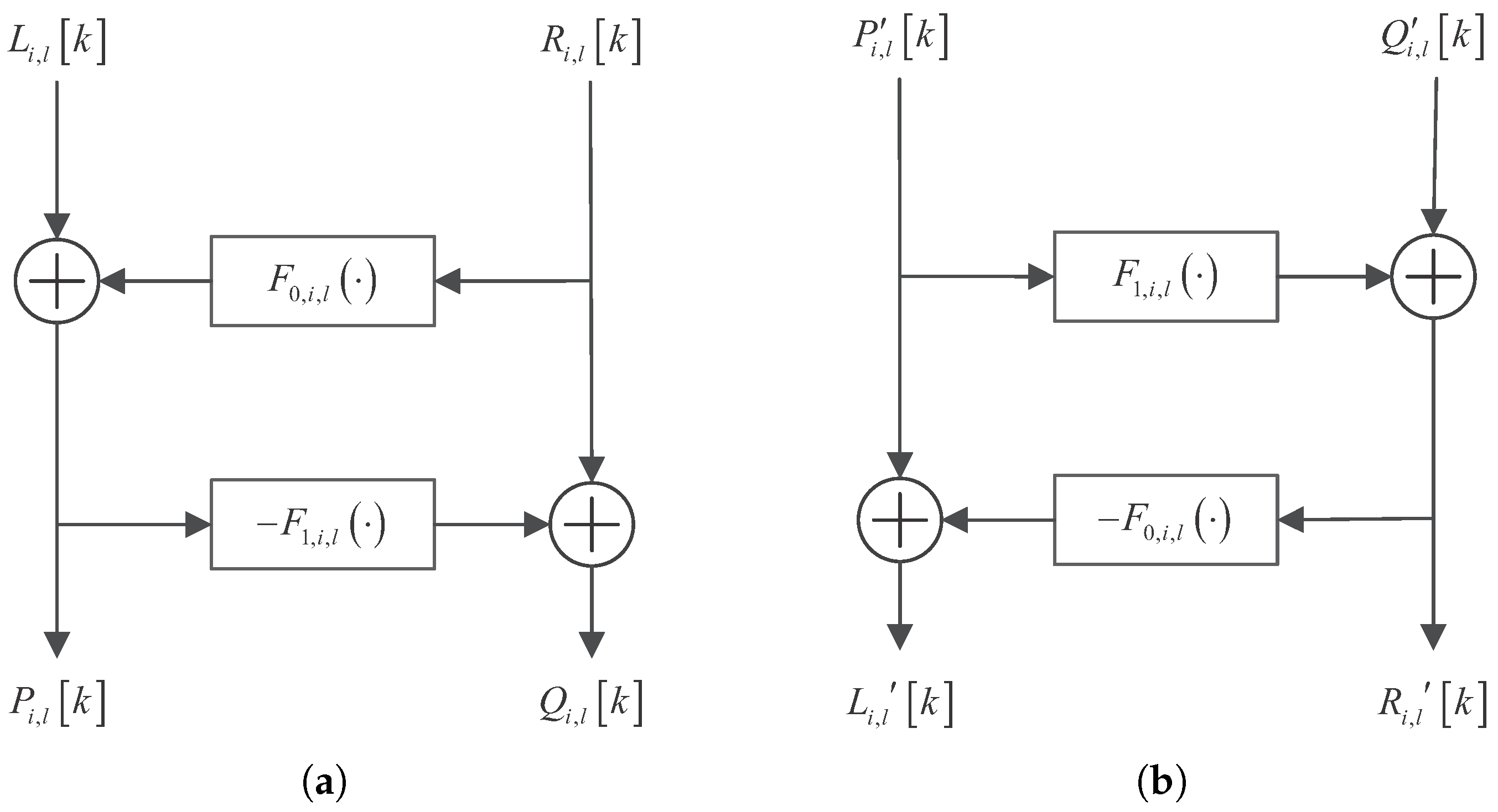
2.2. Dynamics of Nodes in Various Layers of Analysis Network and Synthesis Network

Let γ be the total number of layers in the analysis network. Let σ l for l = 1 , 2 , , γ be the total number of node pairs in the l th layer of the analysis network. Let F j , i , l · , for j = 0 , 1 , for i = 1 , 2 , , σ l , and for l = 1 , 2 , , γ , be the chaotic functions [26] of the j th subband in the i th node of the l th layer of the analysis network. Let λ j , i , l be the parameter in F j , i , l · . Let a j , i , l k , v j , i , l k , and b j , i , l k be the state variable, the input, and the output of F j , i , l · , respectively. Then, the dynamics of F j , i , l · are
a j , i , l k + 1 = λ j , i , l a j , i , l k 1 a j , i , l k
and
b j , i , l k = a j , i , l k + v j , i , l k .
The inputs of the ( i , l ) th analysis node are denoted as L i , l k and R i , l k , and the corresponding outputs are denoted as P i , l k and Q i , l k . Then, the dynamics are
P i , l k = L i , l k + F 0 , i , l ( R i , l k , a 0 , i , l k )
and
Q i , l k = R i , l k F 1 , i , l ( L i , l k , a 1 , i , l k ) .
The structure of the ( i , l ) th node of the analysis network is shown in Figure 3a.
Similarly, the inputs of the ( i , l ) th synthesis node are denoted as P i , l k and Q i , l k , and the corresponding outputs are denoted as L i , l k and R i , l k . Then, the dynamics are
R i , l k = Q i , l k + F 1 , i , l ( P i , l k , a 1 , i , l k )
and
L i , l k = P i , l k F 0 , i , l ( Q i , l k , a 0 , i , l k ) .
The structure of the ( i , l ) th node of the synthesis network is shown in Figure 3b.

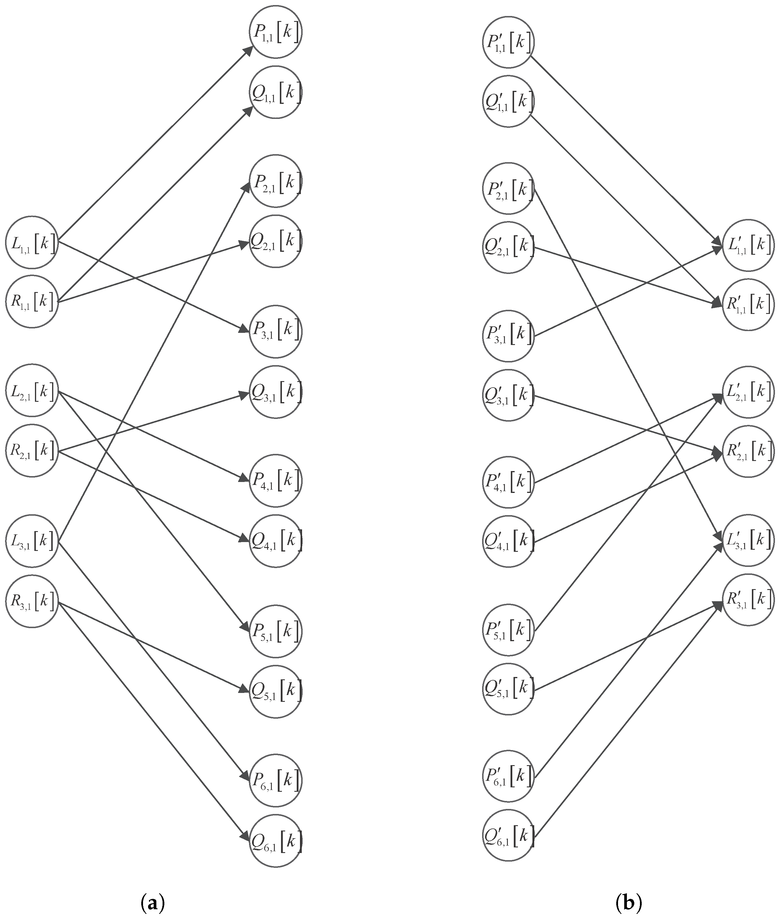
2.3. Multi-Layer Chaotic Network for Performing Multi-Party Verifiable Collaborative Encryption

This paper proposes a multi-layer chaotic filter bank network for performing a multi-party verifiable collaborative encryption. Take the first layer network as an example. L i , 1 k and R i , 1 k are randomly chosen as the inputs of the chaotic filter bank to obtain P i , 1 k and Q i , 1 k , respectively. Also, L i , 1 k and R i , 1 k are taken twice for each i. Thus, σ 2 = 2 σ 1 = 2 σ . Let A l for l = 1 , 2 , , γ be the matrix governing the connection between L i , l k and P i , l k , as well as B l for l = 1 , 2 , , γ be the matrix governing the connection between R i , l k and Q i , l k . Figure 4a shows an example of the first-layer analysis network’s input–output connections. Setting σ 1 = 3 , we observe that
A l R σ 2 × σ 1 = ( α a b ) σ 2 × σ 1 = 1 0 0 0 0 1 1 0 0 0 1 0 0 1 0 0 0 1
and
B l R σ 2 × σ 1 = ( β a b ) σ 2 × σ 1 = 1 0 0 1 0 0 0 1 0 0 1 0 0 0 1 0 0 1 ,
where α i j = 1 if P a , 1 k is the output when L b , 1 k is the input; otherwise, α i j = 0 . Likewise, β i j = 1 if Q a , 1 k is the output when R b , 1 k is the input; otherwise, β i j = 0 .
The analysis network with total γ layers generates σ 2 γ distinct output signals, which are distributed as unique ciphertexts among σ 2 γ recipients. Each recipient thus possesses an exclusive portion of the signal’s complete information.
To decrypt the complete signal, all σ 2 γ distributed ciphertexts must be collected and processed through the synthesis network (Figure 4b), which implements the inverse transformation using matrices A l T and B l T . The system features redundant reconstruction paths, where different inputs (e.g., P 1 , 1 [ k ] and Q 1 , 1 [ k ] , or P 3 , 1 [ k ] and Q 2 , 1 [ k ] ) can yield identical outputs ( L 1 , 1 [ k ] and R 1 , 1 [ k ] ), enabling a built-in verification mechanism. By comparing reconstruction results from independent ciphertexts, the system can detect tampering—successful verification occurs when both paths agree—while discrepancies identify potentially tampered ciphertexts through an analysis of A γ T and B γ T . This design provides both tamper evidence and fault localization while ensuring correct decryption when all parties provide authentic ciphertexts.

3. Security Analysis and Computational Complexity

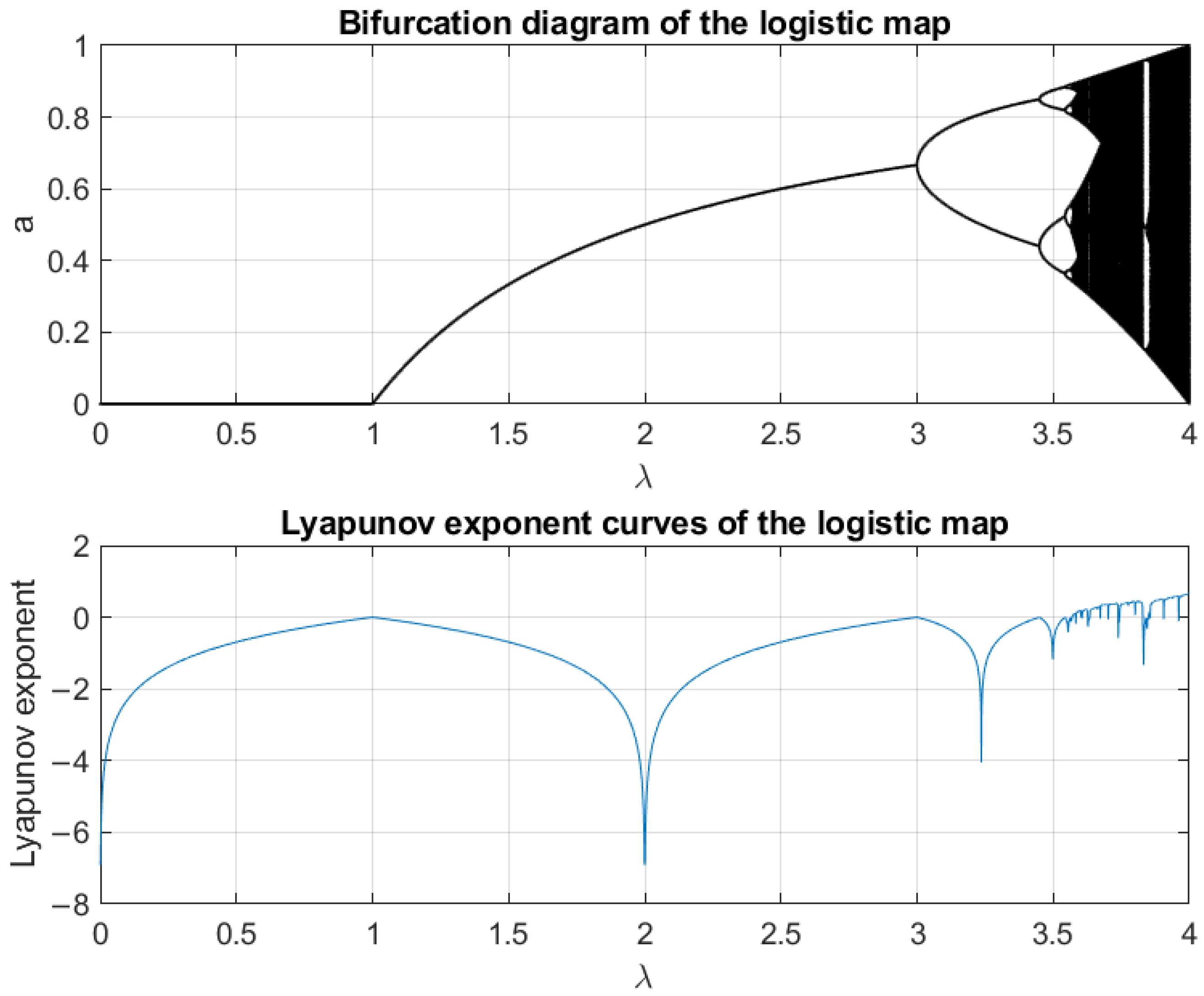
3.1. Dynamic Characteristics of the Logistic Map

The nonlinear dynamical system in (6) exhibits chaotic behavior with state variables a j , i , l k A , where A ( 0 , 1 ) is the state space, and control parameters λ j , i , l B , where B 0 , 4 is the parameter space.
The Lyapunov exponent ϕ for a j , i , l [ k + 1 ] = F j , i , l ( a j , i , l [ k ] ) is
ϕ a j , i , l [ 0 ] = lim T 1 T m = 0 T 1 ln F a j , i , l [ m ] , a j , i , l [ 0 ] A .
Figure 5 shows the bifurcation and Lyapunov diagrams. For λ j , i , l [ 0 , 1 ] , the system has a single fixed point. For λ j , i , l ( 1 , 3 ] , the system has a stable cycle. For λ j , i , l ( 3 , 3.57 ) , the system is periodic doubling. Chaos begins to appear when λ j , i , l reaches Feigenbaum’s universal constant λ . Here, λ 3.57 . When λ j , i , l > 4 , the system is not stable. Thus, the chaotic region is defined as λ j , i , l [ 3.57 , 4 ] .

3.2. Keyspace Analysis

The key consists of λ j , i , l , a j , i , l 0 , A l T , and B l T . Let υ be the window length of SSA. Note that, for typical biological signals, the trajectory matrix X is generally a full-rank matrix, meaning that υ = σ . Let m 1 and m 2 be the storage precision of a j , i , l 0 and λ j , i , l , respectively. The size of the keyspace is
p = 1 γ 2 2 p × 2 υ m 1 × 2 2 p × 2 υ m 2 q = 1 2 γ 2 t = 0 q υ 1 2 q υ 2 t 2 ,
where n k = n ! k ! ( n k ) ! for 0 k n , and ( · ) ! denotes factorial. Compared to the encryption method in [5] with a keyspace of 2 2 m 1 × 2 2 m 2 , the keyspace of the proposed encryption system is greatly improved.

3.3. Algorithmic Complexity Analysis

The system’s computational load arises from SSA (SVD-dominated, O ( υ n 1 2 ) ) and the chaotic filter bank network ( O ( 2 γ + 1 υ n 1 ) ). Decryption requires only O ( 2 γ + 1 υ n 1 ) operations, as it bypasses SVD. For biosignals where n 1 υ , the SVD term governs total encryption cost. To address the computational bottleneck of SSA when processing long signals ( n 1 > 10 3 ), a segmented processing approach can be employed. Apart from that, the chaotic network’s O ( 2 γ + 1 υ n 1 ) cost grows exponentially with γ , but remains tractable for small γ (e.g., γ 4 ).
The ciphertext expansion ratio quantifies the size increase from plaintext to ciphertext in an encryption scheme. This metric directly determines the feasibility of the encryption scheme in real-time biosignal processing. The ciphertext expansion ratio of our proposed method is σ 2 γ , which grows exponentially with the number of design layers γ . However, a five-layer design already offers excellent encryption performance, allowing up to 32 σ parties to access the encrypted signal.

4. Computer Numerical Simulation Results

The real-time monitoring of electroencephalogram (EEG) signals plays a critical role in diagnosing and managing neurological disorders, while photoplethysmogram (PPG) signals provide essential cardiovascular information through heart rate monitoring. Both EEG and PPG exhibit inherent nonlinearity and non-stationarity, making them ideal test cases for evaluating our proposed encryption system. In this study, experimentally acquired EEG and PPG signals are encrypted to demonstrate the system’s effectiveness and flexibility in achieving multi-party cooperative and verifiable encryption for complex biomedical signals. The performance is rigorously compared with the logistic chaotic filter bank encryption method reported in [5] and other mainstream encryption approaches. In the experiments, τ 0 = 0.001 , τ 1 = 0.004 , a 0 , i , l 0 = 0.7 , and a 1 , i , l 0 = 0.9 . In [5], λ 0 = 3.98 and λ 1 = 4.00 . In encrypting based on SSA and the proposed chaotic network, λ 0 , i , l = 3.98 and λ 1 , i , l = 4.00 . To establish a rigorous baseline evaluation of our method’s core functionality, we implemented a minimal test configuration featuring SSA with a conservative window length ( υ 5 ) and a simplified network architecture limited to three layers.

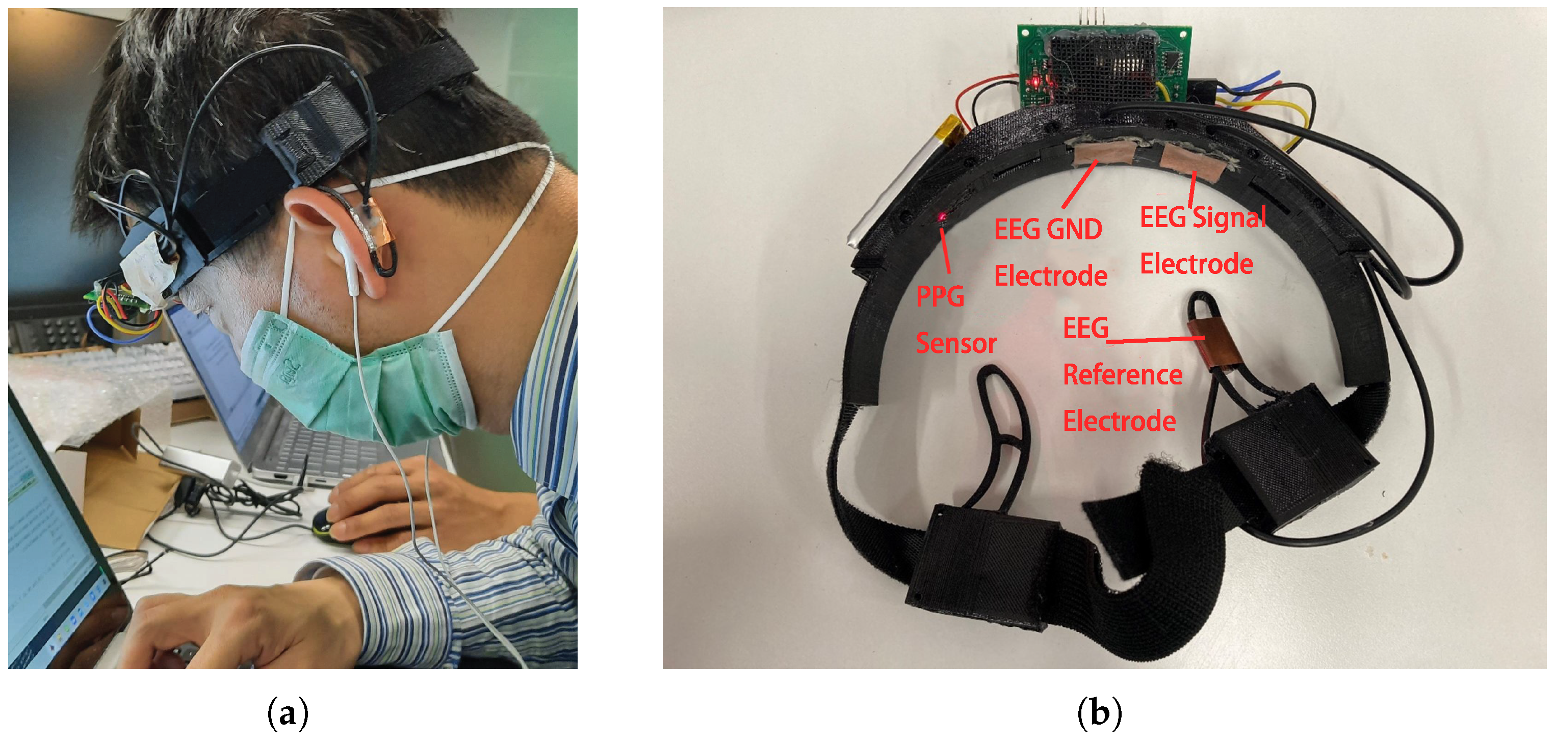
4.1. Data Acquisition

The study employed a custom wearable headband that integrated dual-modality biosignal acquisition. The wearable headband’s design and its deployment in actual measurement scenarios are illustrated in Figure 6, demonstrating the practical usage conditions during physiological signal acquisition. For EEG signal acquisition, we implemented the NeuroSky ThinkGear ASIC Module (TGAM), a specialized biosignal acquisition integrated circuit configured with a 512 Hz sampling frequency. The electrode montage follows standard electrophysiological recording protocols, comprising three essential contact points: the left earlobe serving as reference electrode, the left forehead as EEG signal electrode, and the mid-forehead as GND electrode. Simultaneously, the device incorporates a reflective photoplethysmography sensor positioned at the right forehead to acquire signals at a sampling frequency of 100 Hz.

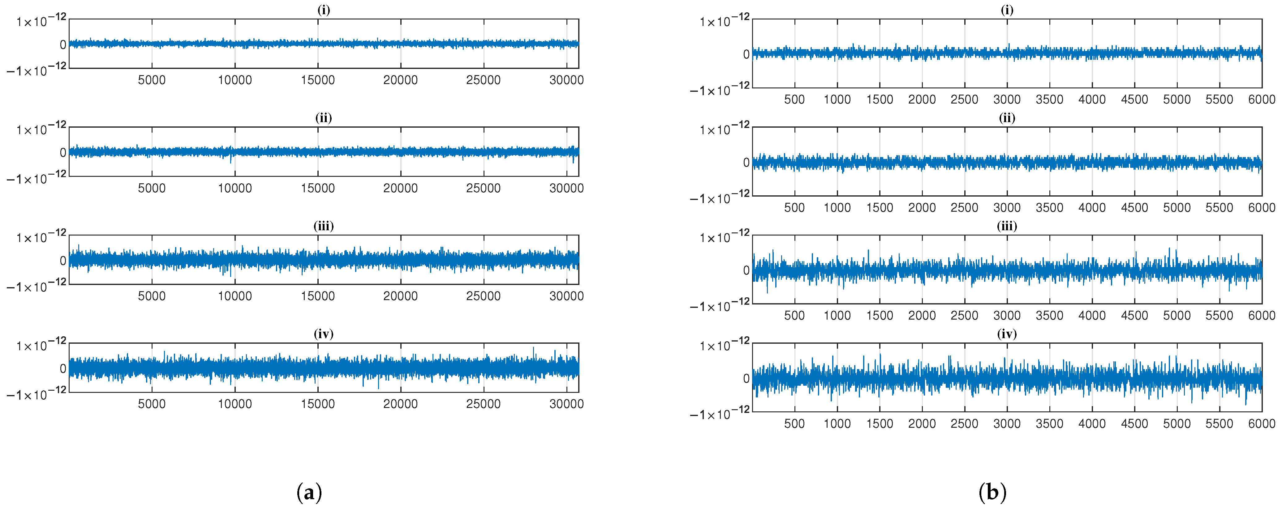
4.2. Reconstruction Error

Figure 7 presents a comparative analysis of decryption reconstruction errors for Figure 7a EEG and Figure 7b PPG across four encryption methods, with each subplot (i)–(iv) representing (i) the logistic chaotic filter bank approach from [5], (ii) our SSA with 1-layer chaotic network, (iii) SSA with 2-layer network, and (iv) SSA with 3-layer network. The results demonstrate consistently minimal reconstruction errors across all methods.
Mean square error (MSE) is used to test the effectiveness of reconstruction accuracy after signal encryption and is defined as
M S E X , Y = i = 1 N x i y i 2 N ,
where X and Y are the original signal and the decrypted reconstruction signals, respectively, and each of the two signals has N scalar observations.
The percentage root-mean-square difference (PRD) is used to assess the degree of distortion in the encryption system and is defined as
P R D X , Y = 100 × i = 1 N x i y i 2 i = 1 N x i 2 ,
and the physical meaning of the variables here is the same as in (16).
Table 1 presents the reconstruction performance metrics (MSE and PRD) for the four evaluated encryption methods. Theoretically, these methods are capable of perfect signal reconstruction, which is substantiated by the experimental results showing extremely low error magnitudes: MSE values on the order of 10 28 to 10 27 and PRD values of 10 14 to 10 13 for both EEG and PPG signals. These negligible errors primarily stem from inherent numerical computation limitations rather than methodological deficiencies. While the approach in [5] demonstrates marginally smaller errors, all methods maintain reconstruction fidelity well within acceptable thresholds.

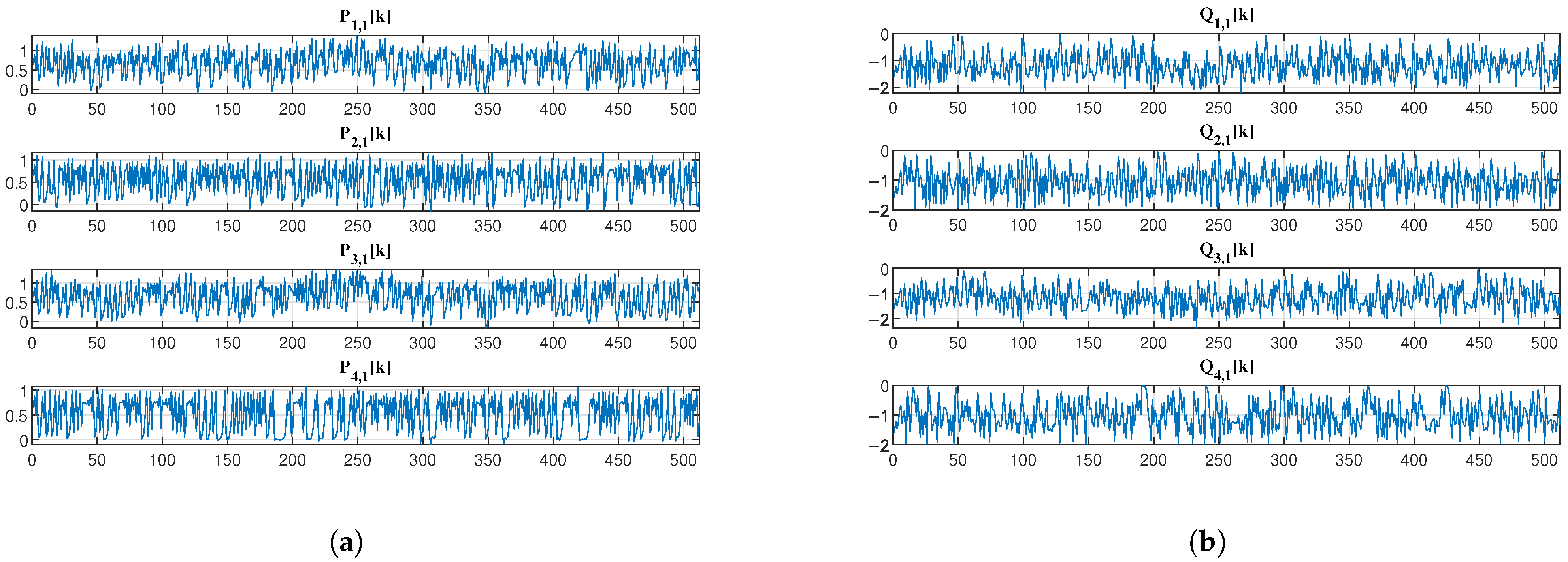
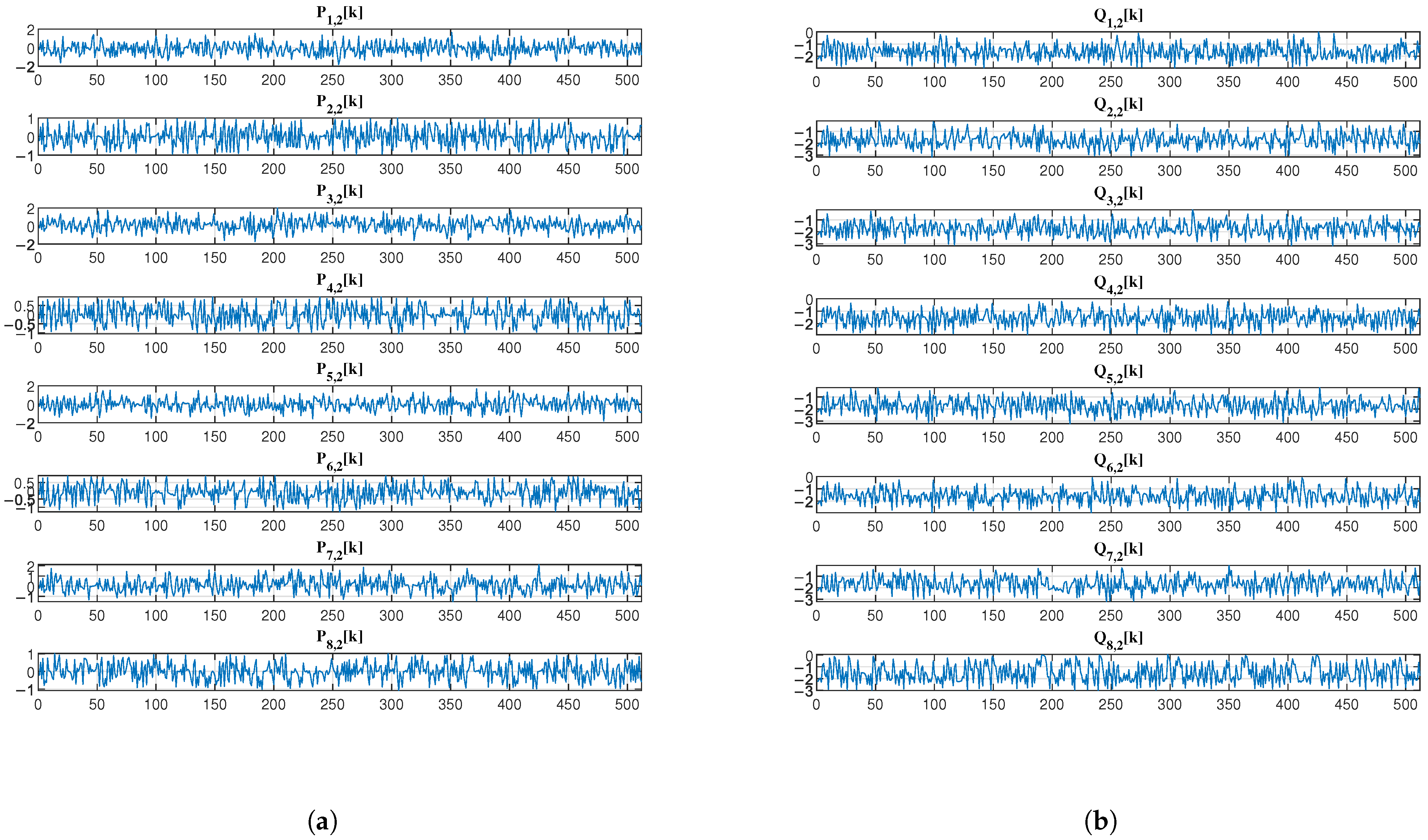
4.3. Signal Processing and Encryption Visualization

For clarity in presentation, Figure 8 displays the 2 s EEG waveform segments along with their corresponding total two SSA components processed through the Haar analysis filter bank.
Figure 9 and Figure 10 further illustrate the output signals of the first layer ( P i , 1 k and Q i , 1 k for i = 1 , 2 , 3 , 4 ) and the second layer ( P i , 2 k and Q i , 2 k for i = 1 , 2 , , 8 ) of the analysis network, respectively. Visually, the encrypted EEG signals exhibit noise-like characteristics with apparent randomness. Compared to the method in [5], our system provides enhanced flexibility in decomposition components, enabling more versatile multi-party collaborative encryption. This is achieved through the hierarchical network structure that generates progressively more components at each layer while maintaining the desired security properties.

4.4. Security Analysis

We conduct a security assessment of the proposed encryption framework by evaluating nine distinct cryptographic approaches: the logistic chaotic filter bank approach [5], our SSA combined with 1-layer, 2-layer, and 3-layer chaotic networks, fully homomorphic encryption (FHE) [14], basic SMPC using simple Lagrange interpolation (Shamir’s scheme) [10], enhanced SMPC with finite field Lagrange interpolation (Robust BGW variant) [11,12], AES-based blockchain encryption, and K-sine-transform-based coupling chaotic system [6]. Our analysis employs three principal security metrics: power spectral density (PSD) analysis to evaluate frequency-domain whitening effects, power ratios analysis to quantify encrypted signal randomness, and correlation analysis assessing both plaintext–ciphertext relationships and inter-ciphertext dependencies.

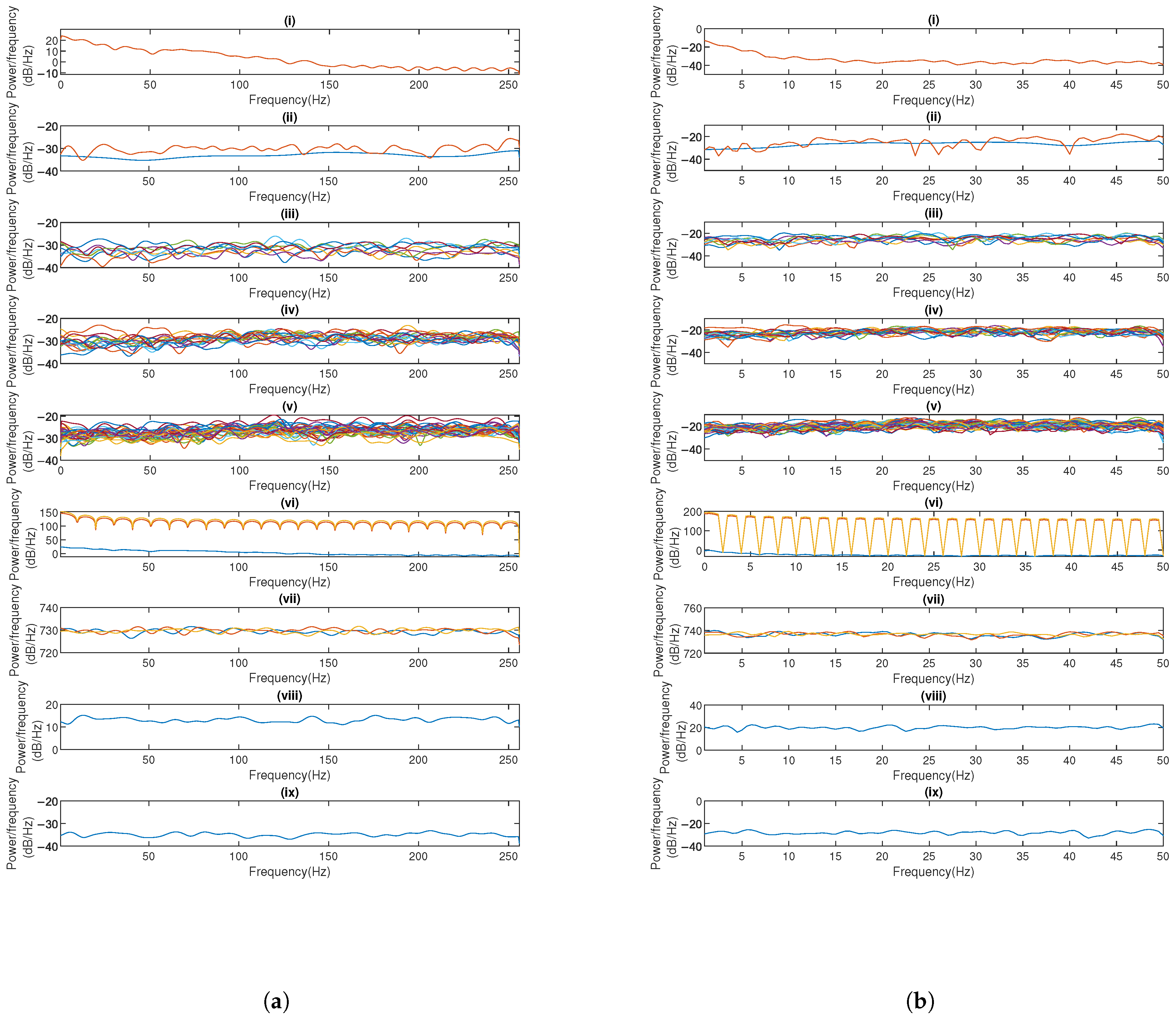
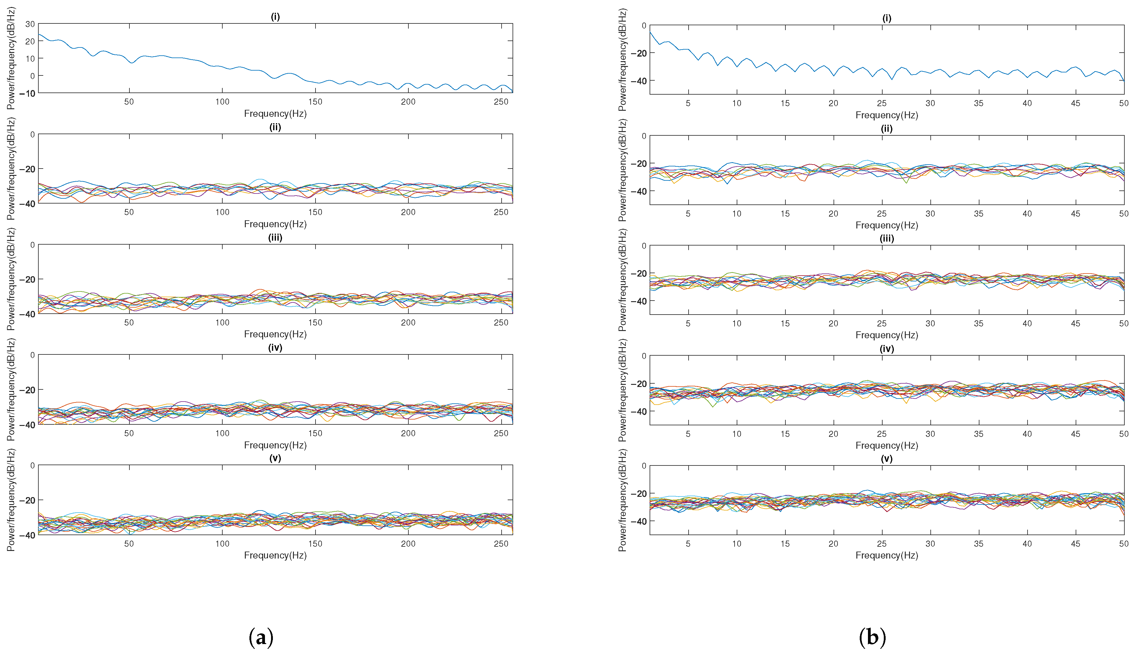
4.4.1. Power Spectral Density Analysis

PSD analysis reveals spectral differences between original and encrypted signals. An ideal encryption produces spectrally uniform outputs resembling white noise. As demonstrated in Figure 11a,b, while original EEG displays characteristic 0–50 Hz neural oscillations and PPG shows 0–5 Hz cardiac rhythms, all tested methods achieve relative spectral whitening, except Shamir’s scheme, which exhibits periodic fading and variations—a potential security weakness for frequency-domain cryptanalysis. In contrast, our 1–3-layer networks consistently generate relatively flat PSD profiles across the entire frequency spectrum (0–256 Hz for EEG, 0–50 Hz for PPG), effectively removing physiological signatures and inter-signal correlations. This spectral uniformity across network depth (1–3 layers) configurations demonstrates robust encryption performance. Given the nature of FHE, where users can only view the results of computations rather than directly accessing the ciphertext, security analyses typically do not encompass FHE.

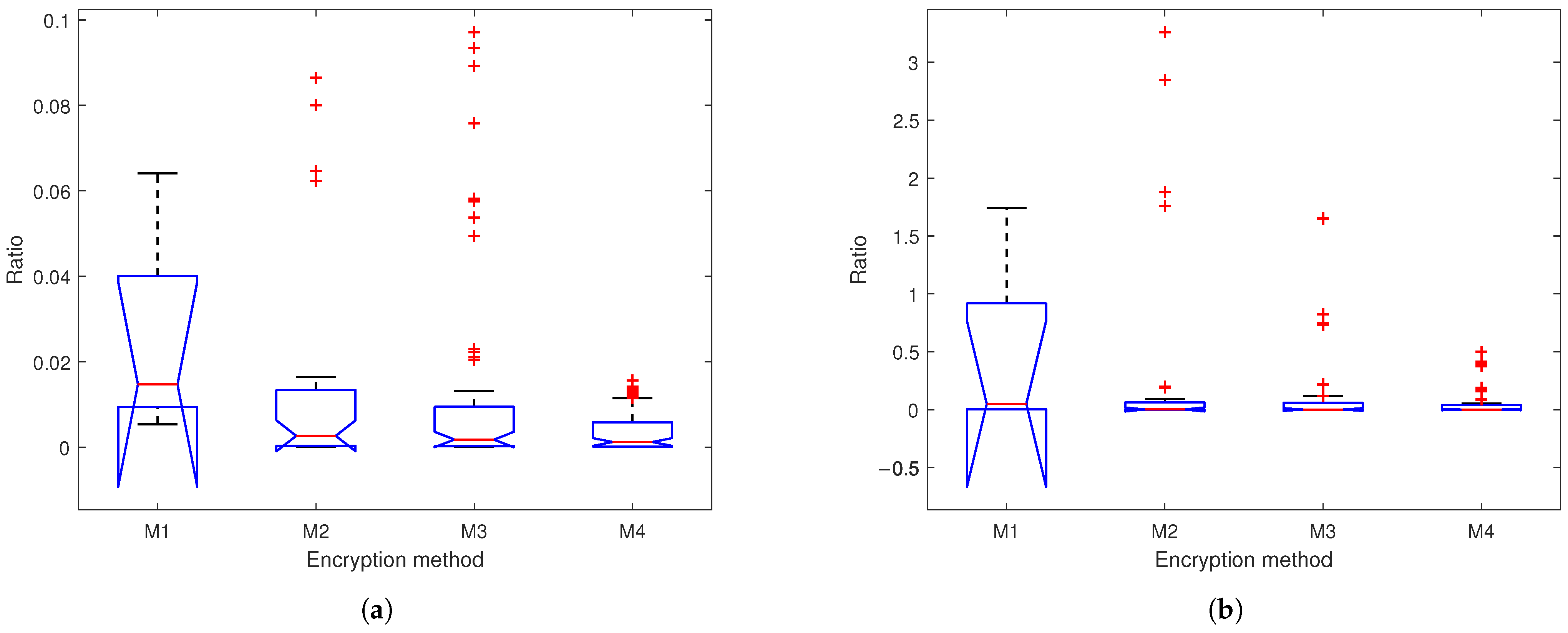
4.4.2. Power Ratio Analysis

The power ratio metric quantifies the encryption strength by comparing the power of input subband signals to their corresponding chaotic encrypted outputs. Figure 12 presents box plots of the power ratios across four encryption methods, where the ratios are defined as k | X i [ k ] | 2 k | ( Y i [ k ] X i [ k ] ) | 2 , (where X is input, Y is output, and i = 1 , 2 ) for M1 and k | L i , l [ k ] | 2 k | ( P i , l [ k ] L i , l [ k ] ) | 2 or k | R i , l [ k ] | 2 k | ( Q i , l [ k ] R i , l [ k ] ) | 2 for M2–M4. The results demonstrate a progressively stronger suppression of signal residual energy across network depths, with median ratios approaching zero and distributions becoming tighter in deeper layers. This consistent reduction in power ratios confirms the enhanced security of our SSA with the multi-layer encryption method, significantly increasing the difficulty in recovering original information.
Table 2 further compares nine encryption methods, revealing that methods based on Shamir’s scheme and the robust BGW variant show complete signal suppression. Notably, methods based on AES and K-sine-transform exhibit higher absolute means (>0.48 for EEG, >1.0 for PPG).

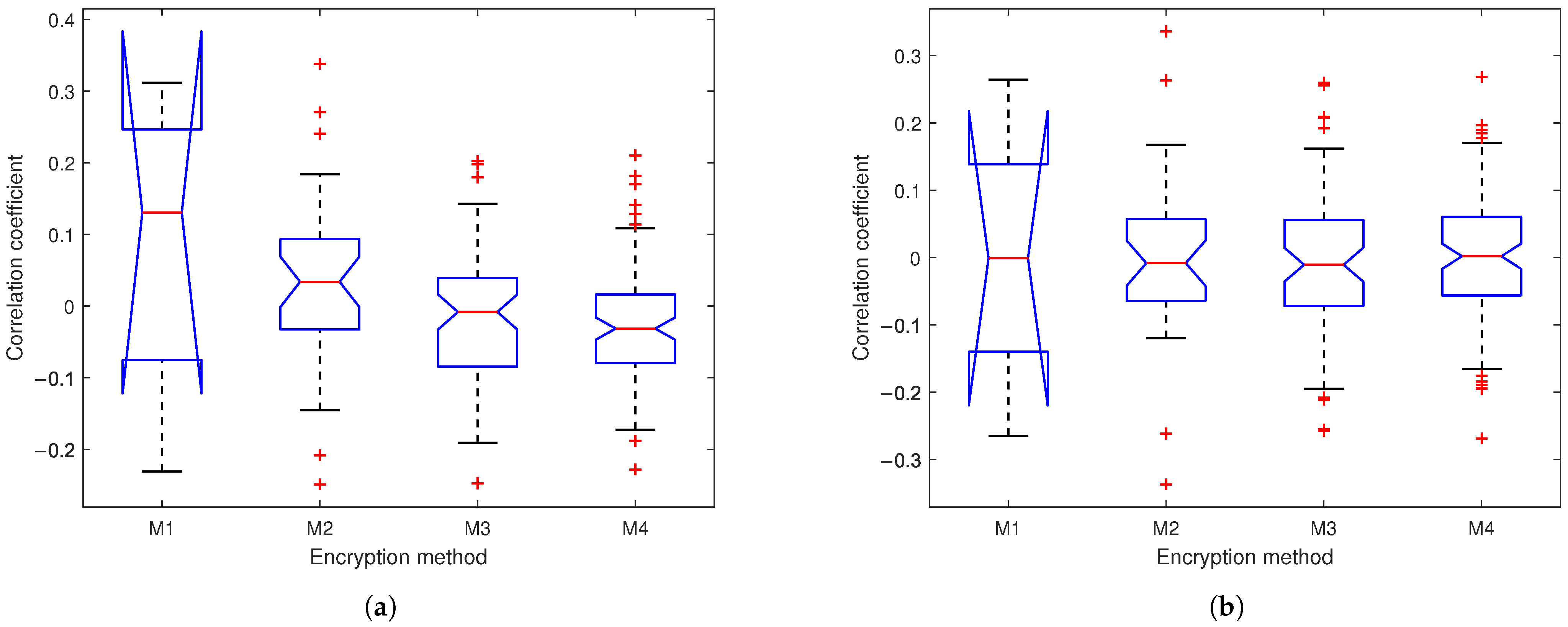
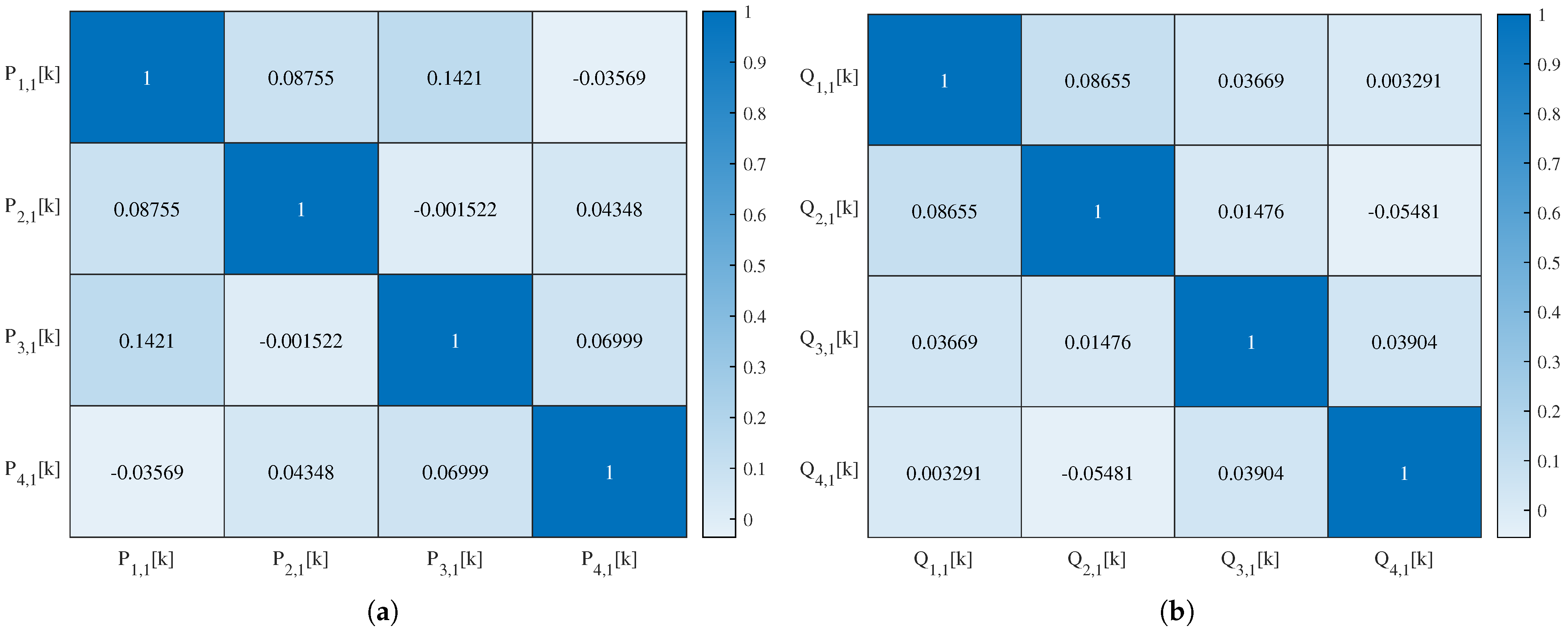
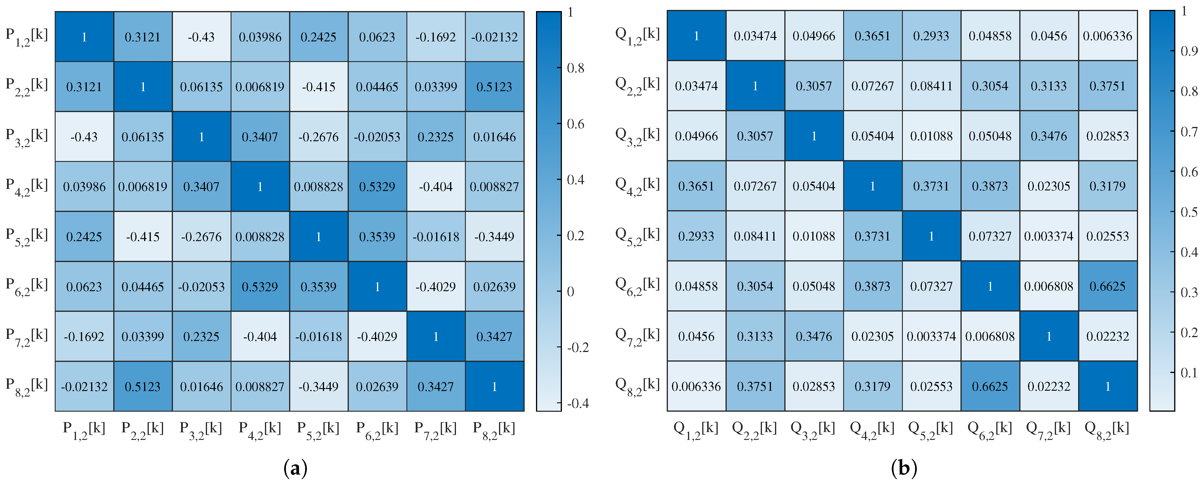
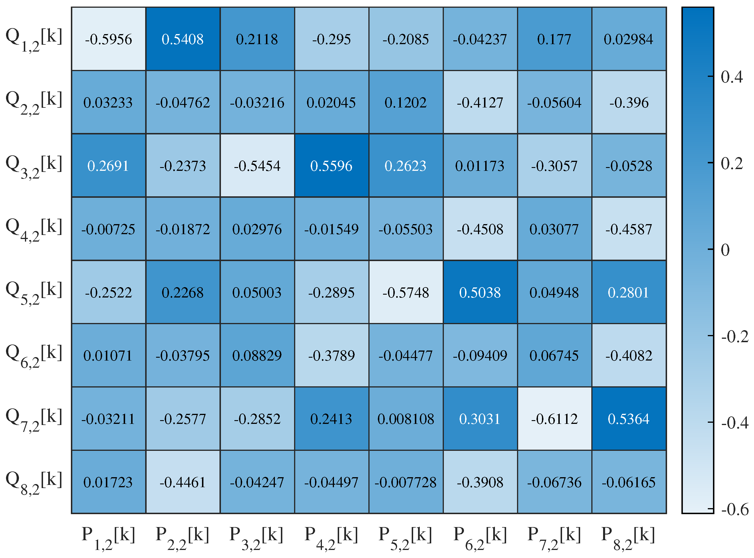
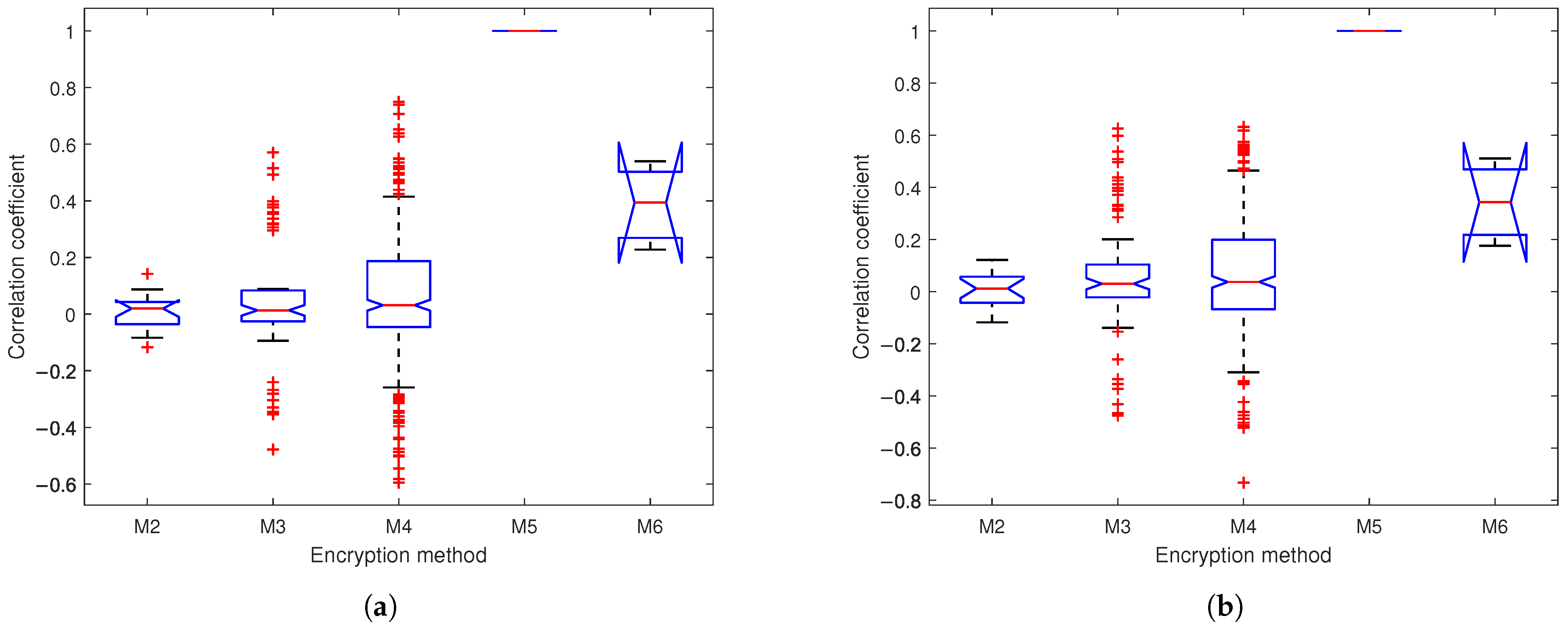
4.4.3. Correlation Analysis

A system is considered well-encrypted if the encrypted signals are highly uncorrelated with the original pre-encryption signals and if the different parts of the encrypted ciphertext block are also uncorrelated with each other. These properties prevent plaintext recovery from partial ciphertext and enforce collaborative decryption, where all parties’ ciphertexts are required for reconstruction.
The correlation coefficient of two signals is defined as
r X , Y = 1 N i = 1 N x i X ¯ σ X y i Y ¯ σ Y ,
where X ¯ and Y ¯ are the average of these two signals, respectively, i.e., X ¯ = 1 N i = 1 N x i and Y ¯ = 1 N i = 1 N y i , and σ X and σ Y are the variance of these two signals, respectively, i.e., σ X = i = 1 N x i X ¯ 2 N and σ Y = i = 1 N y i Y ¯ 2 N .
Figure 13 presents the correlation coefficients between inputs and outputs across four encryption methods (M1–M4). For M1, the correlation coefficients between the polyphase filter outputs and the chaotic encryption outputs. For M2–M4, the correlation coefficients between inputs L i , l k , R i , l k and outputs P i , l k , Q i , l k are calculated. Results show progressively lower correlations from M1 to M4 with medians approaching 0 and tighter coefficient distributions in deeper networks for both EEG and PPG.
Table 3 compares correlation coefficients for nine encryption methods on EEG/PPG signals. While some methods show slightly better decorrelation than our SSA-based chaotic network, our approach achieves sufficiently low correlations (<0.1) that decrease further with network depth (3-layer: EEG = 0.0545, PPG = 0.0641). All methods outperform Shamir’s scheme and [5], with EEG consistently showing better decorrelation than PPG.
Define the autocorrelation coefficient matrix of the X i , for i = 1 , 2 , , m as
R a = r X 1 , X 1 r X 1 , X 2 r X 1 , X m r X 2 , X 1 r X 2 , X 2 r X 2 , X m r X m , X 1 r X m , X 2 r X m , X m ,
and the intercorrelation coefficient matrix of the X i and Y i , for i = 1 , 2 , , m as
R i = r X 1 , Y 1 r X 1 , Y 2 r X 1 , Y m r X 2 , Y 1 r X 2 , Y 2 r X 2 , Y m r X m , Y 1 r X m , Y 2 r X m , Y m .
The 1-layer SSA-chaotic network produces four subband outputs, with their autocorrelation and interrelation matrices’ heat maps visualized in Figure 14 and Figure 15, respectively. For the 2-layer variant (eight outputs), the corresponding matrices’ heat maps are shown in Figure 16 and Figure 17. For conciseness, only the autocorrelation and interrelation matrices of the EEG encrypted by the 1-layer and 2-layer networks are presented here.
The other correlation coefficients for encrypted signals were classified as follows: weak ( | r X , Y |   < 0.3 ), moderate ( 0.3 | r X , Y |   < 0.7 ), and strong ( | r X , Y |   0.7 ), based on established statistical conventions. For the 1-layer chaotic mapping network, most coefficients fell in the weak range, with fewer moderate (e.g., | r L 2 , 1 , L 1 , 1 |   = 0.50 ) or strong (e.g., | r R 3 , 1 , L 1 , 1 |   = 0.89 ) cases. For the 2-layer chaotic mapping network, coefficients are generally weak, with a few moderate or strong correlations.
Figure 18 presents box plot comparisons of encrypted signals’ intercorrelations for EEG and PPG across five multi-party encryption methods. Our approach consistently outperforms the other two comparison methods across network depths (1-layer to 3-layer), with 1-layer correlations < 0.1 (excluding outliers)—significantly lower than M4 ( > 0.2 ) and M5 (≈1 median). While correlations increase slightly with deeper networks, our method relatively outperforms alternatives, demonstrating robust security against correlation attacks while preserving multi-layer practicality for multi-party systems where threshold decryption is required.

4.5. Verification Performance

Our experimental results validate the verification mechanism described in Section 2.3, where the system’s redundant architecture enables two independent decryption paths to converge to identical decrypted outputs with remarkable precision. Both the first and second synthesis network layer demonstrate near-perfect decryption consistency, as shown in Table 4 and Table 5, respectively. The paired decryption paths achieve MSE on the order of 10 32 and PRD between 10 15 and 10 10 , with all observed deviations attributable to floating-point arithmetic limitations. The consistent output matching enables tamper detection through deviation monitoring and cryptographic integrity verification without external reference signals.

4.6. Decryption Error Analysis Under Collaborator Tampering Scenarios

We modified the encrypted signal by replacing its first data point with a uniform random value. Although theory predicts near-perfect consistency across synthesis layers and final reconstruction, our experimental results (Table 6) reveal significant discrepancies. Quantitative evaluation using MSE and PRD metrics demonstrates that even minimal ciphertext alterations (as small as 0.2%) produce clearly detectable tampering artifacts in the decrypted output.

4.7. Encryption and Decryption Efficiency Analysis

During secure channel transmission, the time spent in the encryption and decryption directly impacts data exchange performance. The EEG with a duration of 2 s and the PPG with a duration of 5 s are selected. We test the actual encryption time on a computer with 12th Gen Intel(R) Core(TM) i9-12900K 3.20 GHz processor. The encryption and decryption times are calculated separately for comparison, as shown in Table 7. The results demonstrate that our method achieves millisecond encryption/decryption latency for signal processing, fulfilling the low-latency demands of telemedicine. Morever, the increase in the number of layers does not significantly increase the time required for encryption and decryption. This is probably because the CPU’s processes on the computer cannot be shut down.

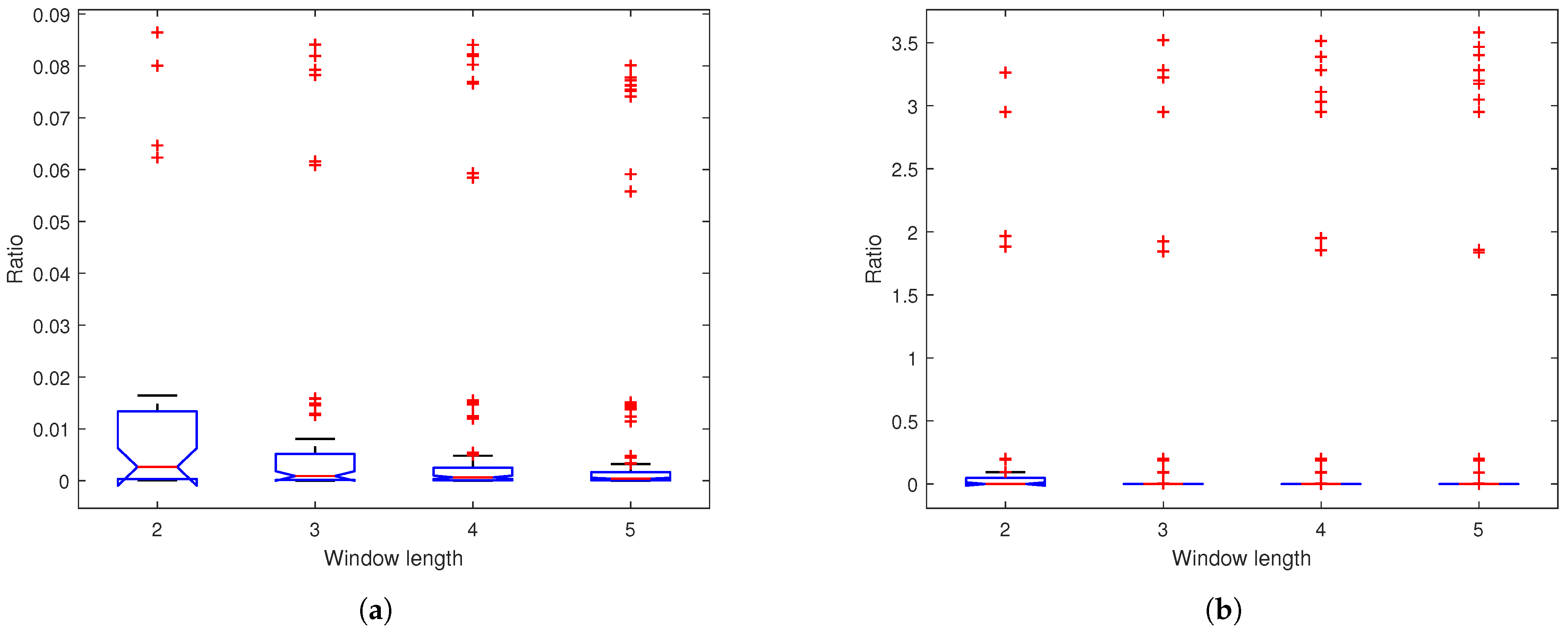
4.8. Performance Across Window Lengths

In this example, we utilize a 1-layer network. Figure 19 displays the box plot of the power ratio for varying SSA window lengths, indicating that, as the window length increases, the distribution range of the ratio diminishes. Table 8 presents the absolute means and variances of correlation coefficients between encrypted and original signals across varying window lengths. The results demonstrate an inverse relationship between window length and correlation coefficients: as window length increases, both the absolute mean and variance of the correlation coefficients decrease. While longer window length reduces correlation coefficients, it also increases computational costs from SVD. Therefore, optimal window lengths should balance these factors. Figure 20 presents the PSD of encrypted signals across varying window lengths. The results show consistently flat frequency spectra, indicating stable encryption performance regardless of window length.

5. Conclusions

This paper presents a verifiable multi-party encryption system for biosensor signals using SSA-based chaotic filter bank networks, demonstrating three key advances: (1) adaptive SSA decomposition with window-length-optimized component extraction for non-stationary EEG and PPG, (2) enhanced chaotic performance through multi-layer chaotic filter bank network diffusion, and (3) integrated consistency verification for collaborative decryption. The computer simulation results demonstrate that the proposed encryption system exhibits robust performance across enhanced key complexity, with the security validated and improved computational efficiency.
However, SMPC retains inherent limitations that our approach will overcome through flexible storage–communication tradeoffs in future deployments, specifically, (1) ciphertexts will remain opaque to all participants while enabling multi-party decryption through distributed key sharing, eliminating SMPC’s massive communication overhead at the cost of increased local storage demands; and (2) planned hardware-aware SSA optimizations will address real-time processing efficiency for clinical biosensor applications.

Author Contributions

Conceptualization, X.Z. and B.W.-K.L.; methodology, X.Z. and B.W.-K.L.; software, X.Z., J.H. and B.W.-K.L.; validation, X.Z., J.H. and B.W.-K.L.; formal analysis, X.Z., J.H. and B.W.-K.L.; investigation, X.Z., J.H. and B.W.-K.L.; resources, B.W.-K.L.; data curation, B.W.-K.L.; writing—original draft preparation, X.Z., J.H. and B.W.-K.L.; writing—review and editing, X.Z., J.H. and B.W.-K.L.; visualization, X.Z. and J.H.; supervision, B.W.-K.L.; project administration, B.W.-K.L.; funding acquisition, B.W.-K.L. All authors have read and agreed to the published version of the manuscript.

Funding

This paper was supported partly by the National Nature Science Foundation of China (no. U1701266, no. 61671163, and no. 62071128), the Team Project of the Education Ministry of Guangdong Province (no. 2017KCXTD011), the Guangdong Higher Education Engineering Technology Research Center for Big Data on Manufacturing Knowledge Patent (no. 501130144), and the Hong Kong Innovation and Technology Commission, Enterprise Support Scheme (no. S/E/070/17).

Institutional Review Board Statement

The study was conducted in accordance with the Declaration of Helsinki, and approved by the Ethics Committee of Academic Ethics and Technology Ethics Special Committee of Guangdong University of Technology (GDUTXS20250146 and 6 January 2025).

Informed Consent Statement

Informed consent was obtained from all subjects involved in the study. Written informed consent has been obtained from the patient(s) to publish this paper.

Data Availability Statement

Data are contained within the article.

Conflicts of Interest

The authors declare no conflicts of interest.

References

  1. Jalali, M.S.; Landman, A.; Gordon, W.J. Telemedicine, privacy, and information security in the age of COVID-19. J. Am. Med. Inform. Assoc. 2020, 28, 671–672. [Google Scholar] [CrossRef] [PubMed]
  2. Lai, J.; Deng, R.H.; Guan, C.; Weng, J. Attribute-Based Encryption With Verifiable Outsourced Decryption. IEEE Trans. Inf. Forensics Secur. 2013, 8, 1343–1354. [Google Scholar]
  3. Ali, Z.; Imran, M.; Alsulaiman, M.; Zia, T.; Shoaib, M. A zero-watermarking algorithm for privacy protection in biomedical signals. Future Gener. Comput. Syst. 2018, 82, 290–303. [Google Scholar] [CrossRef]
  4. Shannon, C.E. Communication theory of secrecy systems. Bell Syst. Tech. J. 1949, 28, 656–715. [Google Scholar] [CrossRef]
  5. Ling, B.W.-K.; Ho, C.Y.-F.; Tam, P.K.-S. Chaotic filter bank for computer cryptography. Chaos Solitons Fractals 2007, 34, 817–824. [Google Scholar] [CrossRef]
  6. Wen, D.; Jiao, W.; Li, X.; Wan, X.; Zhou, Y.; Dong, X.; Lan, X.; Han, W. The EEG signals encryption algorithm with K-sine-transform-based coupling chaotic system. Inf. Sci. 2023, 622, 962–984. [Google Scholar] [CrossRef]
  7. Chen, J.; Ling, B.W.-K.; Feng, P.; Lei, R. Computer cryptography through performing chaotic modulation on intrinsic mode functions with non-dyadic number of encrypted signals. IET Signal Process. 2019, 13, 7–13. [Google Scholar] [CrossRef]
  8. Soleymani, A.; Nordin, M.J.; Sundararajan, E. A Chaotic Cryptosystem for Images Based on Henon and Arnold Cat Map. Sci. World J. 2014, 2014, 536930. [Google Scholar] [CrossRef] [PubMed]
  9. Zhao, C.; Zhao, S.; Zhao, M.; Chen, Z.; Gao, C.Z.; Li, H.; Tan, Y.A. Secure multi-party computation: Theory, practice and applications. Inf. Sci. 2019, 476, 357–372. [Google Scholar] [CrossRef]
  10. Zhou, I.; Tofigh, F.; Piccardi, M.; Abolhasan, M.; Franklin, D.; Lipman, J. Secure multi-party computation for machine learning: A survey. IEEE Access 2024, 12, 53881–53899. [Google Scholar] [CrossRef]
  11. Yu, Q.; Li, S.; Raviv, N.; Kalan, S.M.M.; Soltanolkotabi, M.; Avestimehr, S.A. Lagrange coded computing: Optimal design for resiliency, security, and privacy. In Proceedings of the 22nd International Conference on Artificial Intelligence and Statistics, Naha, Okinawa, Japan, 16–18 April 2019. [Google Scholar]
  12. Ben-Or, M.; Goldwasser, S.; Wigderson, A. Completeness theorems for non-cryptographic fault-tolerant distributed computation. In Providing Sound Foundations for Cryptography: On the Work of Shafi Goldwasser and Silvio Micali; Association for Computing Machinery: New York, NY, USA, 2019; pp. 351–371. [Google Scholar]
  13. Al Badawi, A.; Bates, J.; Bergamaschi, F.; Cousins, D.B.; Erabelli, S.; Genise, N.; Halevi, S.; Hunt, H.; Kim, A.; Lee, Y.; et al. Openfhe: Open-source fully homomorphic encryption library. In Proceedings of the 10th Workshop on Encrypted Computing & Applied Homomorphic Cryptography, Los Angeles, CA, USA, 7 November 2022. [Google Scholar]
  14. Chillotti, I.; Joye, M.; Ligier, D.; Orfila, J.B.; Tap, S. Concrete: Concrete operates on ciphertexts rapidly by extending tfhe. In Proceedings of the WAHC 2020-8th Workshop on Encrypted Computing & Applied Homomorphic Cryptography, Virtual, 15 December 2020. [Google Scholar]
  15. Mukherjee, P.; Wichs, D. Two round multiparty computation via multi-key FHE. In Proceedings of the Advances in Cryptology–EUROCRYPT 2016: 35th Annual International Conference on the Theory and Applications of Cryptographic Techniques, Vienna, Austria, 8–12 May 2016. [Google Scholar]
  16. Kocabas, O.; Soyata, T.; Couderc, J.P.; Aktas, M.; Xia, J.; Huang, M. Assessment of cloud-based health monitoring using homomorphic encryption. In Proceedings of the 2013 IEEE 31st International Conference on Computer Design (ICCD), Asheville, NC, USA, 6–9 October 2013. [Google Scholar]
  17. Xie, Q.; Jiang, S.; Jiang, L.; Huang, Y.; Zhao, Z.; Khan, S.; Dai, W.; Liu, Z.; Wu, K. Efficiency optimization techniques in privacy-preserving federated learning with homomorphic encryption: A brief survey. IEEE Internet Things 2024, 11, 24569–24580. [Google Scholar] [CrossRef]
  18. Tamilselvi, P.; Lathika, V.; Jayachitra, S.; Arunkumar, S.; Balasubramani, M.; Kalaichelvi, V. Secure Multi-Party Computation for Collaborative Data Analysis in Network Security. In Proceedings of the 2024 International Conference on Intelligent and Innovative Technologies in Computing, Electrical and Electronics (IITCEE), Bengaluru, India, 24–25 January 2024. [Google Scholar]
  19. Battah, A.A.; Madine, M.M.; Alzaabi, H.; Yaqoob, I.; Salah, K.; Jayaraman, R. Blockchain-Based Multi-Party Authorization for Accessing IPFS Encrypted Data. IEEE Access 2020, 8, 196813–196825. [Google Scholar] [CrossRef]
  20. Hidayat, T.; Mahardiko, R. Data encryption algorithm AES by using blockchain technology: A review. BACA J. Dok. Dan Inf. 2021, 42, 19–30. [Google Scholar] [CrossRef]
  21. Shamir, A. How to share a secret. Commun. ACM 1979, 22, 612–613. [Google Scholar] [CrossRef]
  22. Pournaghi, S.M.; Bayat, M.; Farjami, Y. MedSBA: A novel and secure scheme to share medical data based on blockchain technology and attribute-based encryption. J. Ambient. Intell. Humaniz. Comput. 2020, 11, 4613–4641. [Google Scholar] [CrossRef]
  23. Cafaro, M.; Pellè, P. Space-Efficient Verifiable Secret Sharing Using Polynomial Interpolation. IEEE Trans. Cloud Comput. 2018, 6, 453–463. [Google Scholar] [CrossRef]
  24. Soman, A.K.; Vaidyanathan, P.P. On orthonormal wavelets and paraunitary filter banks. IEEE Trans. Signal Process. 1993, 41, 1170–1183. [Google Scholar] [CrossRef]
  25. Vaidyanathan, P.P. Multirate digital filters, filter banks, polyphase networks, and applications: A tutorial. Proc. IEEE 1990, 78, 56–93. [Google Scholar] [CrossRef]
  26. Ulam, S.M. On combination of stochastic and deterministic processes. Bull. Am. Math. Soc. 1947, 53, 1120. [Google Scholar]
Figure 1. The framework of the proposed encryption and decryption system.
Sensors 25 03823 g001
Figure 2. (a) The analysis and (b) synthesis system of the proposed method.
Sensors 25 03823 g002
Figure 3. The structure of the ( i , l ) th node of the (a) analysis and (b) synthesis network.
Sensors 25 03823 g003
Figure 4. An example ( σ 1 = 3 , σ 2 = 6 ) of the input–output connections of the first layer in (a) analysis and (b) synthesis chaotic filter bank network.
Sensors 25 03823 g004
Figure 5. Bifurcation diagram and Lyapunov exponent curve of the logistic map.
Sensors 25 03823 g005
Figure 6. The wearable headband’s (a) deployment in actual measurement scenarios and (b) design for EEG and PPG acquisition.
Sensors 25 03823 g006
Figure 7. Reconstruction error of the 1 min (a) EEG and (b) PPG across four encryption methods, with each subplot (i)–(iv) representing (i) the logistic chaotic filter bank approach from [5], (ii) our SSA with 1-layer chaotic network, (iii) SSA with 2-layer network, and (iv) SSA with 3-layer network.
Sensors 25 03823 g007
Figure 8. The raw EEG and, for each SSA component ( i = 1 , 2 ) , the corresponding outputs of the Haar analysis filter bank: the low-frequency subband signal L i , 1 k and the high-frequency subband signal R i , 1 k of the first-layer analysis network.
Sensors 25 03823 g008
Figure 9. The output EEG (a) low-frequency subband signal P i , 1 k and (b) high-frequency subband signal Q i , 1 k of the first-layer analysis network.
Sensors 25 03823 g009
Figure 10. The output EEG (a) low-frequency subband signal P i , 2 k and (b) high-frequency subband signal Q i , 2 k of the second-layer analysis network.
Sensors 25 03823 g010
Figure 11. Encrypted signal’s PSD of (a) EEG and (b) PPG across eight encryption methods, with each subplot representing (i) the raw signal, (ii) the logistic chaotic filter bank approach from [5], (iii) our SSA with 1-layer chaotic network, (iv) our SSA with 2-layer network, (v) our SSA with 3-layer network, (vi) basic SMPC with simple Lagrange interpolation (Shamir’s scheme), (vii) enhanced SMPC with finite field Lagrange interpolation (Robust BGW variant), (viii) AES-based blockchain, and (ix) K-sine-transform-based coupling chaotic system.
Sensors 25 03823 g011
Figure 12. Box plots of ratios of (a) EEG and (b) PPG based on M1: chaotic filter bank in [5]; M2: our SSA with 1-layer chaotic network; M3: our SSA with 2-layer network; M4: our SSA with 3-layer chaotic network.
Sensors 25 03823 g012
Figure 13. Box plots of correlation coefficients between inputs and outputs for (a) EEG and (b) PPG based on M1: chaotic filter bank in [5]; M2: our SSA with 1-layer chaotic network; M3: our SSA with 2-layer network; M4: our SSA with 3-layer chaotic network.
Sensors 25 03823 g013
Figure 14. Heat map of the autocorrelation coefficient of (a) P i , 1 k and (b) Q i , 1 k of EEG encrypted by the 1-layer network.
Sensors 25 03823 g014
Figure 15. Heat map of the interrelation coefficient of EEG encrypted by the 1-layer network.
Sensors 25 03823 g015
Figure 16. Heat map of the autocorrelation coefficient of (a) P i , 2 k and (b) Q i , 2 k of EEG encrypted by the 2-layer network.
Sensors 25 03823 g016
Figure 17. Heat map of the interrelation coefficient of EEG encrypted by the 2-layer network.
Sensors 25 03823 g017
Figure 18. Box plots of correlation coefficients between encrypted signals for (a) EEG and (b) PPG based on M2: our SSA with 1-layer chaotic network; M3: our SSA with 2-layer network; M4: our SSA with 3-layer chaotic network; M5: Shamir’s scheme; M6: robust BGW variant.
Sensors 25 03823 g018
Figure 19. Box plots of ratios for (a) EEG and (b) PPG based on our SSA with 1-layer chaotic network (window length: 2–5).
Sensors 25 03823 g019
Figure 20. Encrypted signal’s PSD of (a) EEG and (b) PPG based on our SSA with 1-layer chaotic network, with each subplot representing (i) original, (ii) the SSA window length of 2, (iii) the SSA window length of 3, (iv) the SSA window length of 4, and (v) the SSA window length of 5.
Sensors 25 03823 g020
Table 1. The reconstruction performance metrics (MSE and PRD) based on the logistic chaotic filter bank in [5], our SSA with 1-layer chaotic network, our SSA with 2-layer chaotic network, and our SSA with 3-layer chaotic network.
SignalEEGPPG
Encryption MethodsMSEPRDMSEPRD
Logistic chaotic filter bank of [5] 1.6335 × 10 27 3.7036 × 10 14 5.4749 × 10 27 1.6972 × 10 14
Our SSA with 1-layer chaotic network 3.6665 × 10 27 5.5487 × 10 14 9.2309 × 10 27 2.2038 × 10 14
Our SSA with 2-layer chaotic network 1.2784 × 10 26 1.0361 × 10 13 1.6074 × 10 26 2.9081 × 10 14
Our SSA with 3-layer chaotic network 1.7115 × 10 26 1.1988 × 10 13 2.9525 × 10 26 3.9413 × 10 14
Table 2. The absolute means and variances of power ratios for 2 s EEG and 5 s PPG accross nine encryption methods.
SignalEEGPPG
Encryption MethodsAbsolute MeanVarianceAbsolute MeanVariance
Logistic chaotic filter bank in [5]0.02480.00050.46100.5483
Our SSA with 1-layer chaotic network0.01330.00060.32550.6895
Our SSA with 2-layer chaotic network0.01240.00060.12140.1095
Our SSA with 3-layer chaotic network0.00390.00000.04790.0096
FHE 1
Shamir’s scheme 0.0000 0.0000 0.0000 0.0000
Robust BGW variant 0.0000 0.0000 0.0000 0.0000
AES-based blockchain 2 0.4836 1.8669
K-sine-transform-based coupling
chaotic system 3
1.0085 1.0023
1 The methods based on FHE was excluded from absolute mean and variance calculations due to the ciphertext cannot be obtained. 2,3 The methods based on AES-based blockchain and K-sine-transform were excluded from variance calculations because they do not support multi-party encryption.
Table 3. The absolute means and variances of the correlation coefficients for 2 s EEG and 5 s PPG accross nine encryption methods.
SignalEEGPPG
Encryption MethodsAbsolute MeanVarianceAbsolute MeanVariance
Logistic chaotic filter bank in [5]0.20100.04010.13930.0351
Our SSA with 1-layer chaotic network0.09820.01560.08500.0154
Our SSA with 2-layer chaotic network0.07560.00920.08470.0125
Our SSA with 3-layer chaotic network0.05450.00460.06410.0069
FHE
Shamir’s scheme100.95890
Robust BGW variant 0.0402 0.0014 0.0490 0.0008
AES-based blockchain 0.0263 0.0285
K-sine-transform-based coupling
chaotic system
0.0264 0.0607
Table 4. Matching MSE and PRD of paired decryption outputs for EEG and PPG in the first synthesis network layer.
SignalEEGPPG
Paired Decryption ResultsMSEPRDMSEPRD
L 1 , 1 k 4.3886 × 10 32 1.3091 × 10 13 8.2765 × 10 32 3.2995 × 10 14
L 2 , 1 k 3.3727 × 10 32 2.0994 × 10 12 3.9067 × 10 32 3.4297 × 10 10
R 1 , 1 k 5.4613 × 10 32 3.1783 × 10 13 8.5657 × 10 32 9.2950 × 10 13
R 2 , 1 k 1.0464 × 10 32 1.1596 × 10 12 7.0762 × 10 32 3.9852 × 10 11
Table 5. Matching MSE and PRD of paired decryption outputs for EEG and PPG in the second synthesis network layer.
SignalEEGPPG
Paired Decryption ResultsMSEPRDMSEPRD
L 1 , 2 k 2.3699 × 10 32 2.0693 × 10 14 4.5569 × 10 32 1.4695 × 10 14
L 2 , 2 k 2.2611 × 10 32 2.3431 × 10 14 2.4928 × 10 32 2.4944 × 10 14
L 3 , 2 k 2.6543 × 10 32 1.1282 × 10 14 4.4123 × 10 32 1.4652 × 10 14
L 4 , 2 k 2.1918 × 10 32 2.2143 × 10 14 2.1516 × 10 32 2.3808 × 10 14
R 1 , 2 k 2.3678 × 10 32 1.2006 × 10 14 2.7943 × 10 32 8.3029 × 10 15
R 2 , 2 k 2.0284 × 10 32 1.2224 × 10 14 3.1065 × 10 32 1.5161 × 10 14
R 3 , 2 k 1.8907 × 10 32 1.0872 × 10 14 2.9558 × 10 32 8.7092 × 10 15
R 4 , 2 k 2.1714 × 10 32 1.2914 × 10 14 2.9434 × 10 32 1.5228 × 10 14
Table 6. Matching MSE and PRD of paired decryption outputs for EEG and PPG in 2-layer synthesis network.
SignalEEGPPG
Paired Decryption ResultsMSEPRDMSEPRD
x k 19.7632 5.4167 19.55511.0225
L e r r o r , 1 k or R e r r o r , 1 k 0.0013 43.0444 0.001247.6284
L e r r o r , 2 k or R e r r o r , 2 k 0.0013 3.0426 0.00123.0111
Table 7. Encryption time and decryption time of EEG and PPG.
SignalEEGPPG
Encryption MethodsEncryption Time (s)Decryption Time (s)Encryption Time (s)Decryption Time (s)
Logistic chaotic filter bank in [5]0.00170.00170.00160.0018
Our SSA with 1-layer chaotic network0.00780.00500.00830.0025
Our SSA with 2-layer chaotic network0.00980.00660.00630.0015
Our SSA with 3-layer chaotic network0.00860.00110.00980.0067
FHE 0.1132 0.0196 0.09660.0125
Shamir’s scheme 0.0002 0.0001 0.00020.0001
Robust BGW variant 0.0023 0.0048 0.0012 0.0017
AES-based blockchain 0.0005 0.0001 0.00060.0001
K-sine-transform-based coupling
chaotic system
0.0142 0.0092 0.00790.0078
Table 8. The absolute mean and variance of the correlation coefficients between encrypted and original signals based on our SSA with 1-layer chaotic network (window length: 2–5).
SignalEEGPPG
Window LengthAbsolute MeanVarianceAbsolute MeanVariance
20.09820.04010.08500.0154
30.06330.00740.07260.0108
40.05430.00550.05980.0075
50.04800.00430.06060.0065
Disclaimer/Publisher’s Note: The statements, opinions and data contained in all publications are solely those of the individual author(s) and contributor(s) and not of MDPI and/or the editor(s). MDPI and/or the editor(s) disclaim responsibility for any injury to people or property resulting from any ideas, methods, instructions or products referred to in the content.

