Design and Implementation of a Novel IoT Architecture for Data Release System Between Multiple Platforms: Case of Smart Offshores
Abstract
1. Introduction
1.1. Study Overview and Challenges
1.2. Study Objectives
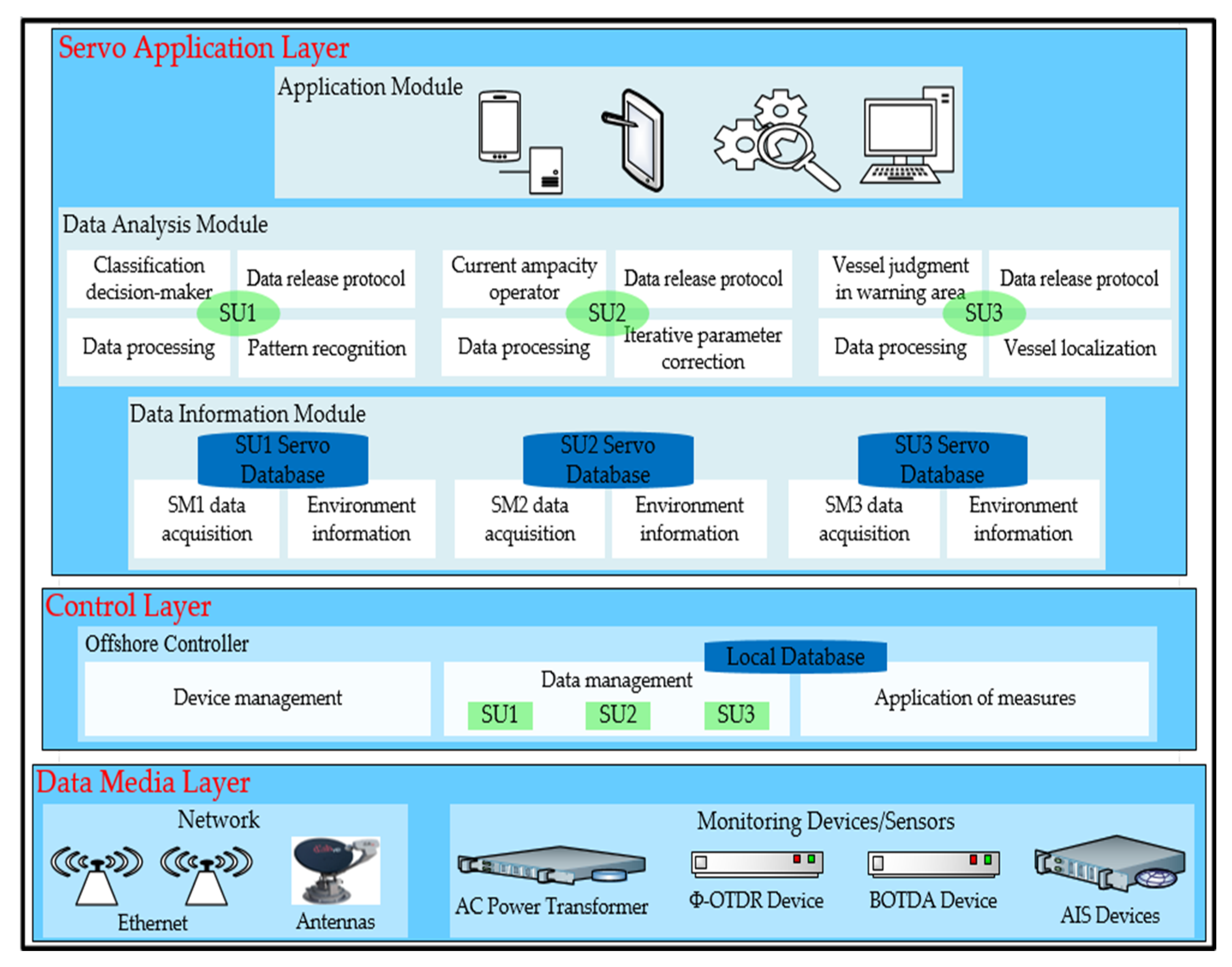
- The novel IoT architecture was designed with three layers: a data media layer, a control layer, and a servo application layer. The functions of these layers are to acquire, process, analyze, and release data in real-time. This IoT architecture makes it possible to evaluate data in order to improve its execution and release.
- The data types and files to be transferred are dynamically configured using IEC104 protocols to ensure an efficient and fast data release.
- The proposed IoT architecture was deployed in a real scenario in order to execute the data release of the photoelectric composite submarine cable and its environment. The experimental results obtained from the testing datasets during this deployment are presented using the proposed approach.
2. Related Work
2.1. IoT Architectures for Smart Fields
2.2. Common IoT Architecture for Marine Environment
2.3. IEC60870-5-104 Protocol to Evaluate Data Release
3. IoT Architecture for Data Release
3.1. Data Media Layer
3.2. Control Layer
3.2.1. Device Management Unit
3.2.2. Data Management Unit
3.2.3. Application of Measures Unit
3.3. Servo Application Layer
3.3.1. Data Information Module
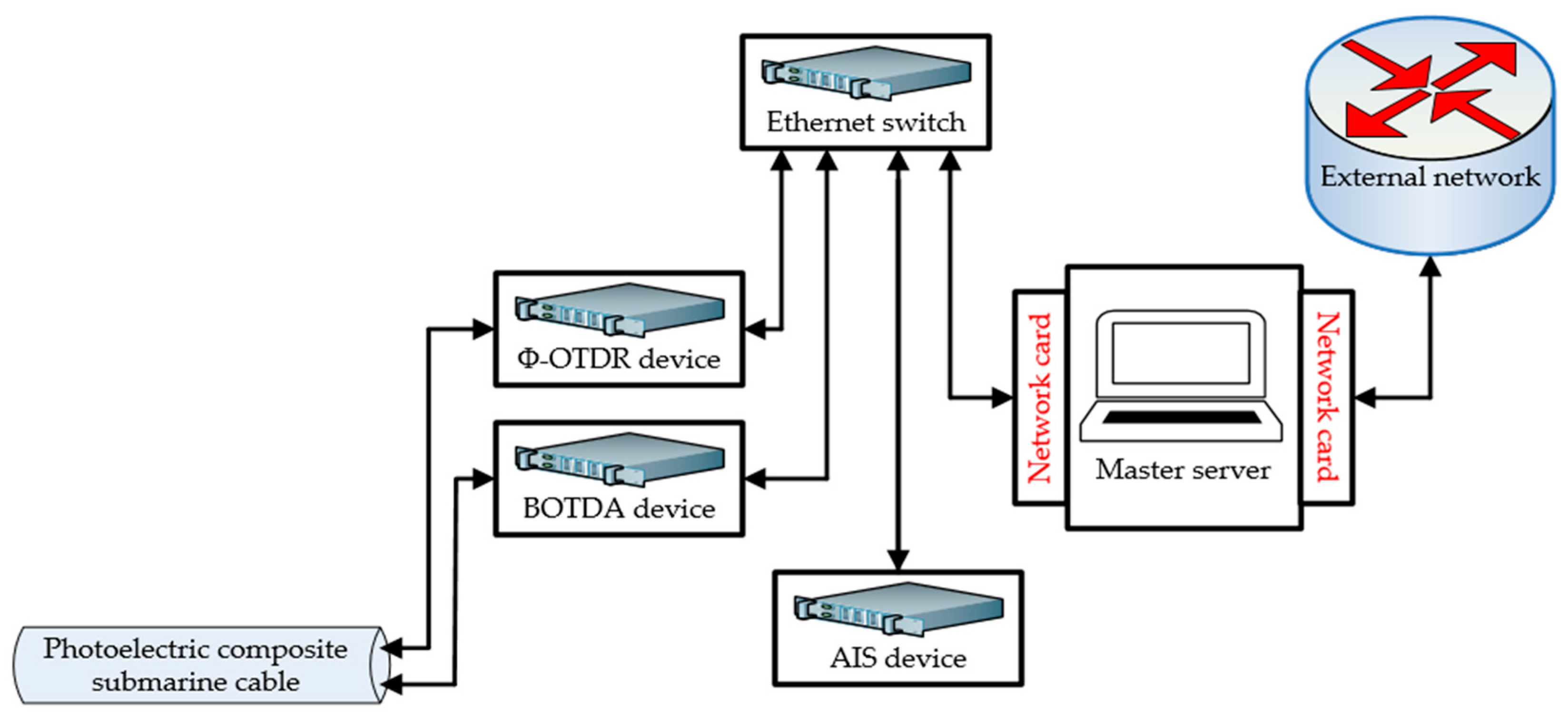
- Data acquisition Unit: It receives information from the OC deployed in the facility and is responsible for storing it in the corresponding servo database. This information includes data from the sensor and OC itself. In addition, each OC is identified by a unique identifier allocated to it during installation, which links the data stored in the database.
- Environment information unit: The purpose of this unit is to coordinate and aggregate the data collected by each sensor located in the data acquisition unit and store it in its corresponding servo database. It is responsible for extracting environmental information from all these data and making it available for subsequent analysis in the data analysis module. Indeed, the data received from the sensors and provided by the data acquisition unit are available to the data analysis module via the servo database. Since each sensor has its own corresponding servo database, the system continuously updates the data acquired in each servo database.
3.3.2. Data Analysis Module
- Data processing unit: This unit processes all the data stored in the servo database, scales the continuous characteristics present in the datasets, and encodes the class variables following a model appropriate for the problem under study. In addition, it not only provides the possibility to choose these datasets using an approach, but also allows the datasets to be divided while preserving the time consistency of the data. This unit has the same function in each of the three departments; the first, second, and third departments contain SU1, SU2, and SU3, respectively.
- Data release protocol unit: This unit operates in the same way in each of the three departments. It completes the underlying DC and remote data release functions based on IEC104. It parses the data received by the previous unit and simultaneously performs the associated database operations.
3.3.3. Application Module
4. Dynamic Configurations for Data Release
4.1. Monitoring Software System
4.1.1. Implementation of the System Protocol Layer
4.1.2. Server-Side Parameter Configuration
- APCIParameters configuration: The maximum number of APDUs in “I-format” that are not acknowledged by the sender (k = 12); the receiver receives up to the number of APDUs in unacknowledged “I-format” (w = 8); the network timeout period for establishing a connection (t0 = 10); the timeout period for sending or testing the APDU (t1 = 15); the timeout period acknowledged when the receiver has no datagram (t2 = 10), with t2 < t1; and the timeout for sending acknowledgments when the channel is idle for a long time (t3 = 20).
- ApplicationLayerParameters configuration: The number of bytes identified by the type is 1 (sizeOfTypeId = 1); the number of bytes of a variable structure qualifier is 1 (sizeOfVSQ = 1); the number of bytes for the reason for transmission is 2 (sizeOfCOT = 2); the number of bytes of the public address is 2 (sizeOfCA = 2); the number of bytes of the address of the information object is 3 (sizeOfIOA = 3); and the maximum length of ASDU is 249.
- ClientConnectionEvent configuration: The connection is open (OPENED); the connection enters the active state, in which the two communicating parties can exchange data (ACTIVE); the connection enters an inactive state, in which the communicating parties cannot interact with each other (INACTIVE); and the connection is closed (CLOSED).
- ServerMode configuration: Single-connection activation mode (SINGLE_REDUNDANCY_GROUP) and multi-connection activation mode (CONNECTION_IS_REDUNDANCY_GROUP).
- Connection control parameter configuration: The local hostname is “0.0.0.0” (localHostname = “0.0.0.0”); the port number is 2404 (localPort = 2404); the maximum length of the ASDU queue is 1000 (maxQueueSize = 1000); and the maximum number of connections is 10 (maxOpenConnections = 10).
4.2. Dynamic Configuration of Command and Controlled Stations
4.2.1. Dynamic Configuration of a Single Type of Data
4.2.2. Dynamic Configuration of File Transfer
| Algorithm 1. Configuration algorithm |
| <MsgConfig> <MsgType> Information type < TypeId Code=’9’> Normalized telemetry </Code> …… </MsgType> <MsgAddr> Information object address <Current_Begin addr=’0x1’> Power information start address </Current_Begin> <Current_End addr=’0x5000’> Energy information end address </Current_End> …… </MsgAddr> </MsgConfig> |
4.3. File Transfer Application
4.3.1. Transfer of Massive Amounts of Data
4.3.2. Transfer of Complex Types of Data
- File transfer of alarm data: Table 9 shows the configuration of the alarm data type and the number of bytes allocated. It can be seen from the table that the alarm data accounts for 80 bytes; these data are divided into 10 segments, and each segment accounts for 8 bytes.
5. Engineering Application Case
5.1. Experimental Setup
5.2. Experimental Verification
5.2.1. EED1
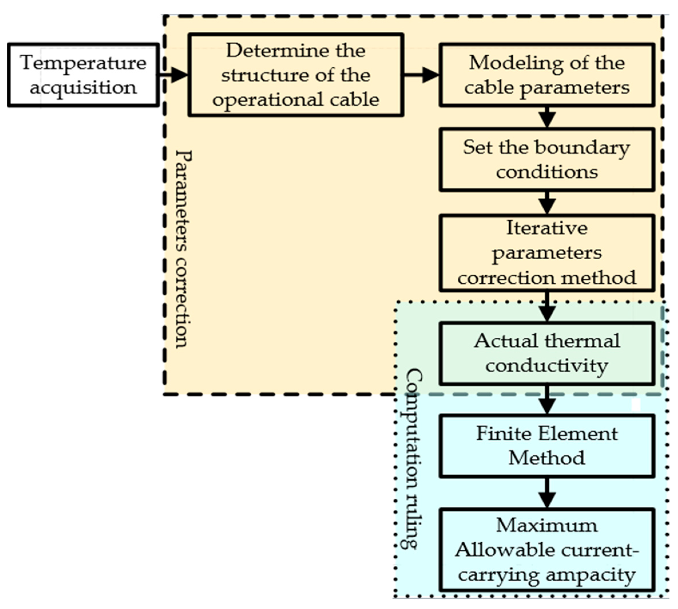
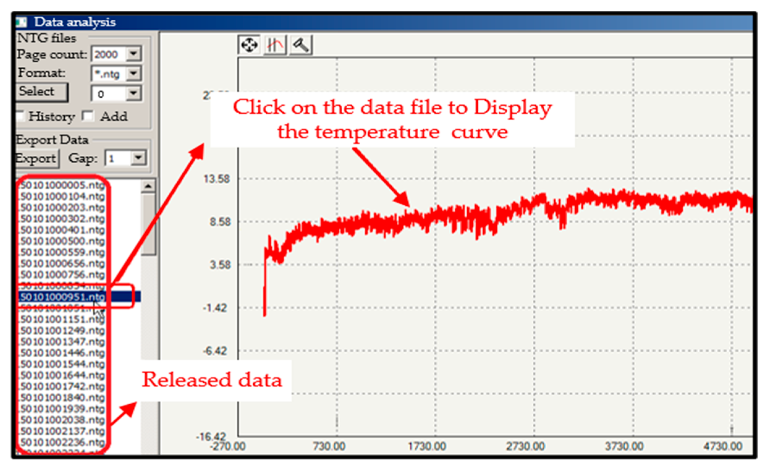
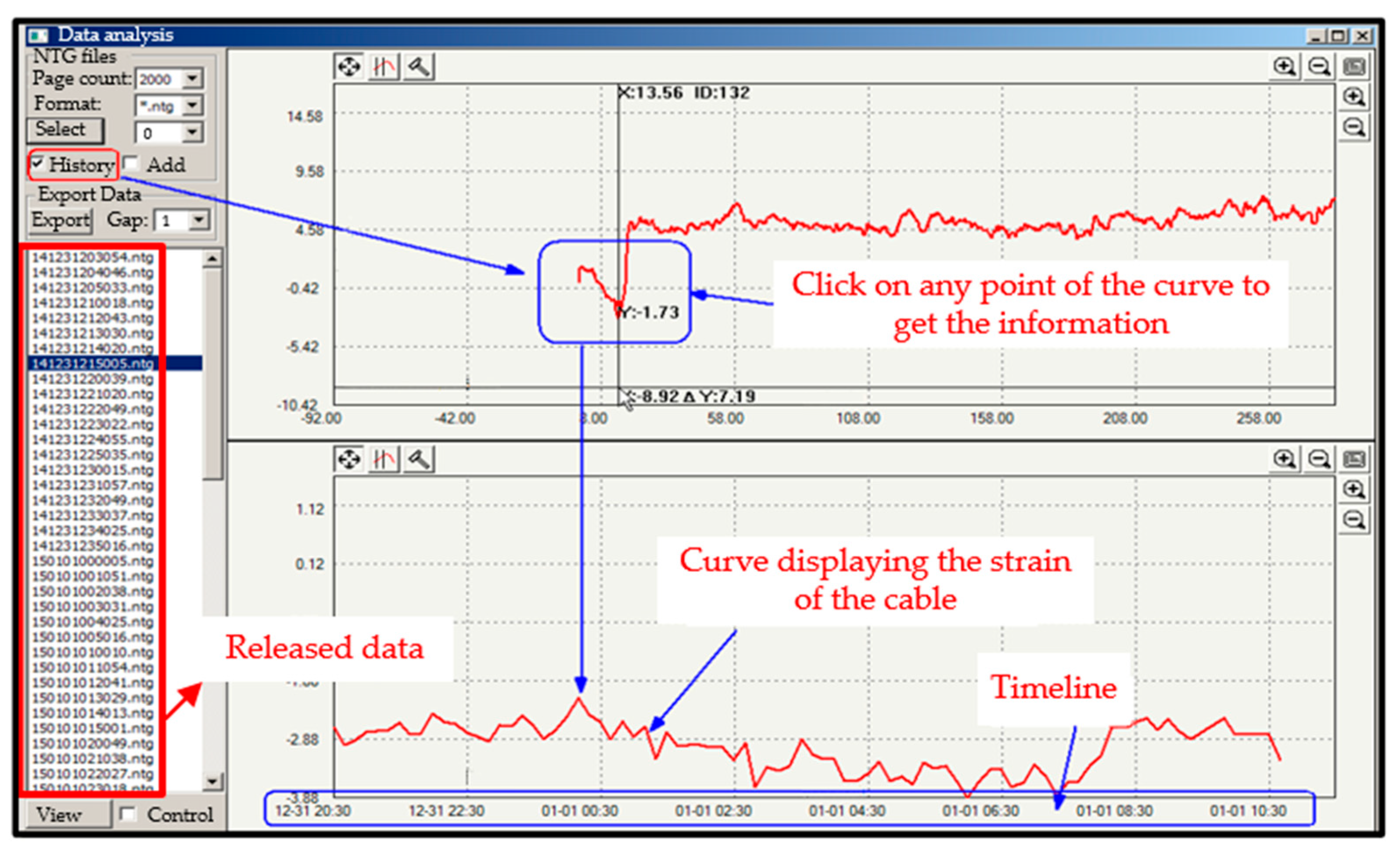
- Data processing unit: Once the data sent by the OC are stored in the SU2 servo database, the next step is to adapt them for use in the designed model IPCM-FEM; this adjustment is performed in the data processing unit. Since the data are collected at different time intervals, preliminary data processing is required to prepare the data before moving on to the next unit. For example, the electrical energy of an XLPE submarine cable depends on its insulation temperature and the electrical resistance of its conductor [44]. The temperature of the underwater soil generally varies between 14 °C and 29 °C depending on the season, and this temperature is very important to know because it influences the calculations to determine the electrical energy. Thus, the insolation temperature of the cable is always collected by the BOTDA device, regardless of the season. However, at the time the experiments were carried out, the temperatures of the seawater and cable insulation were about 20 °C. The convective heat transfer coefficient between soil and seawater is 200 . All this information is stored in a database and is available at any time.
- Iterative parameter correction unit: The IPCM used to correct errors that may occur in the calculation of electrical energy is designed and implemented in this unit. In the temperature field modeling, physical performance parameters such as heat capacity and thermal conductivity of the submarine cable are defined in this unit. For example, and are respectively the final and actual temperatures of the cable insolation, collected in a specific time interval. is a function of (), and is the error limit. If , then is the accurate value; if , then the value of should be corrected. When is not within the error limit, the IPCM is applied using the chord method, which describes how to modify the parameters through the function values of each node obtained by modeling [45]. The formula applied to correct the parameters in this unit is as follows:
- Current ampacity operator unit: The FEM was implemented in this unit. This unit defines not only the geometric model of submarine cable 1 according to its structural parameters and laying environment, but also the physical performance parameters of its different materials. This allows its meshing in order to establish the finite element model. For example, the range of the ambient temperature is , the temperature interval is , and the range of convective heat transfer coefficient is and the interval is . Set the initial ambient temperature as and the initial convective heat transfer coefficient as . Set the initial value of the cable working current to . Input the working current of the cable, the ambient temperature , and the convective heat transfer coefficient in ANSYS modeling software (Version 2022). Then, obtain the temperature field distribution as well as the cable insolation temperature and conductor temperature . Submarine cable 1 has a rated current of 704A, which is confirmed by the steady-state current calculation formulated by the IEC 60287 standard [46]. Based on the result obtained from the previous unit, the parameters go through multiple evaluations before the periodic load factor M is generated by the ANSYS modeling to determine the final electrical energy . Its equation is:
- Data release protocol unit: Data release is executed in this unit following a specific logic. Knowing that electrical energy is a single type of data, the transmission of such data is as follows: Considering the transmission of a single-energy data for submarine cable 1, the configuration parameter information is set as shown in Table A1 (See Appendix A). After the system starts reading the configuration and waits for the data to be summoned, Wireshark software (Version 2023) is used to analyze the network capture of the communication process to obtain the packets received by the command station, as shown in Table A2 (See Appendix A). As shown in Table A2, the code of the transmitted normalized telemetry value is 10a1 (hexadecimal); to obtain the specific transmission value, further calculations are required using the given parameters. The transmission code is as follows:
5.2.2. DD3
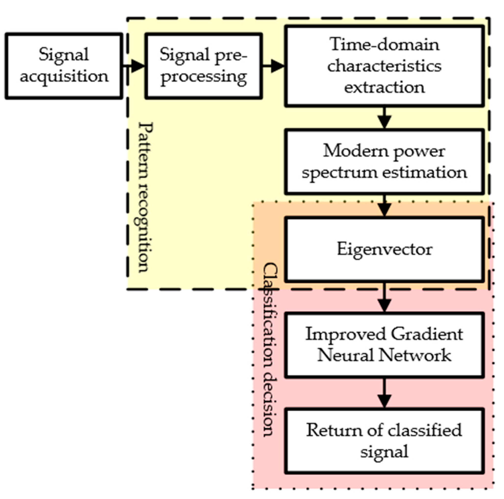
- Data processing unit: As mentioned earlier, when the data sent by the OC are stored in the servo database, they are adapted in the data processing unit for use in the designed MPSE-IGNN model. Since the data are collected under different conditions or at different time intervals, it is necessary to prepare them in this unit before they enter the next unit. For example, when the Φ-OTDR device detects the vibration of the optical fiber of the cable, it indicates that there is a collision event with the cable. The vibration data of the optical fiber of the cable are always collected for processing in order to determine the magnitude and position of the collision event. At the time of the experiment, submarine cable 3 was struck with a thrust force of about 45 Newton by means of a 100 kg iron hammer; this data corresponds to the second class, which can be verified from Table A3 (See Appendix A).
- Pattern recognition unit: The MPSE is used in this unit, which consists of the power distribution of the extracted signal features in the time and frequency domains. For example, the instantaneous energy and instantaneous threshold rate are used to extract signal features from the power distribution in the time-domain through the following equations:
- Classification decision-maker unit: The IGNN is implemented in this unit to determine the types of events corresponding to the eigenvectors formed in the previous unit. The eigenvector is normalized and input into the multiclass IGNN classifier to initiate the extent and position of the collision event in real-time. To evaluate the similarity between the predicted values and eigenvalues, the following equation is used:
- Data release protocol unit: The logic for releasing these data includes the transmission of a disturbance data file for submarine cable 3. Table A4 (See Appendix A) provides its parameter configuration information, from which we can see that the length of the file is 750 KB, the length of the section is 7680 B, and the length of the segment is 120 B. The number of sections and segments is determined as shown in (10) and (11), respectively.
5.2.3. Vessel Arriving at the Warning Zone
- Data processing unit: When the data are stored in the servo database, they are accommodated in this unit for use in the designed model IMM-TDOA/FDOA. Once the data is inserted into this unit, it is scaled before being used in the IMM-TDOA/FDOA model.
- Vessel localization unit: The IMM-TDOA/FDOA model is implemented in this unit using the following equations:
- Vessel judgment in the warning area unit: The vessel position judging model is implemented in this unit to determine whether a short message should be sent to them. For example, if is the point where the vessel is located, the following equation is applied:
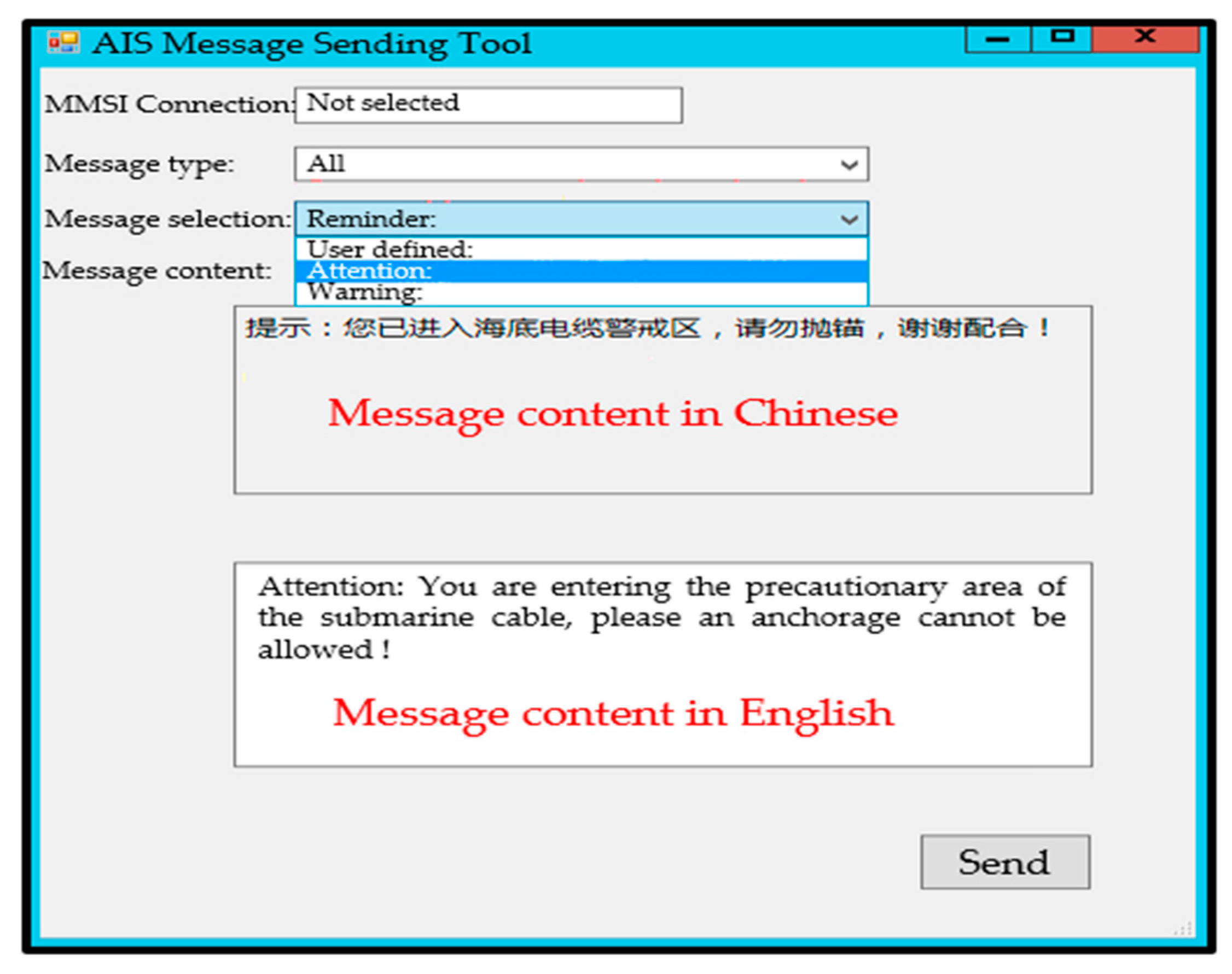
- Data release protocol unit: AIS contains several types of data; therefore, the number of bytes in the data transmission process is not fixed, and address allocation cannot be performed. Therefore, only the file transfer scheme is implemented in this unit. As the AIS contains complex data, its data release follows the following logic. The system defines two AIS devices and automatically allocates the serial port data processing threads. Each serial port data processing thread allocates two thread security queues for transmitting and receiving the data. The INI configuration file is presented in Table A6 (See Appendix A).
5.3. Data Display Software Overview
5.4. Performance Test and Analysis
5.4.1. Electrical Energy Data Release
5.4.2. Disturbance Data Release
5.4.3. Vessels Positioning Data Release
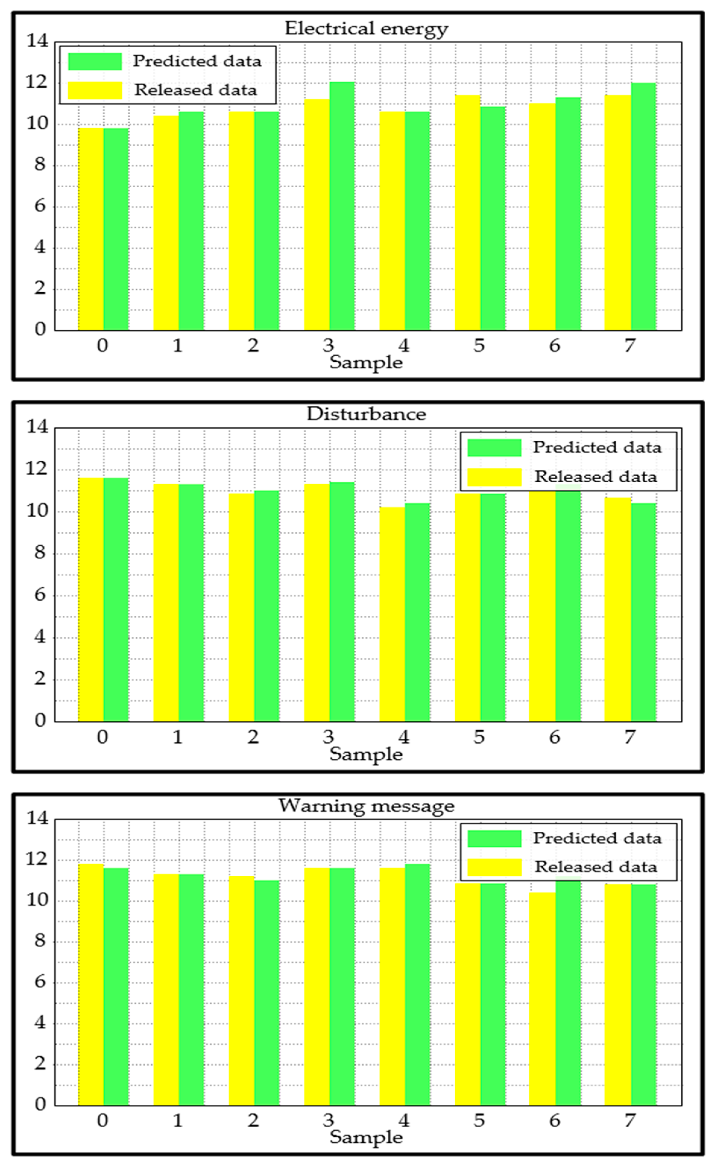
- We can draw the conclusion that, with very few exceptions, the three variables used in the test are predicted quite accurately.
- We can see that regardless of the sample number, there is no significant discrepancy between the three cases.
- The disturbance data are labeled with the highest relative discrepancy in the fourth sample, resulting in a label that does not perform well compared with the other two cases. However, it is evident that the proposed approach produced an acceptable performance.
6. Validation of the Approach
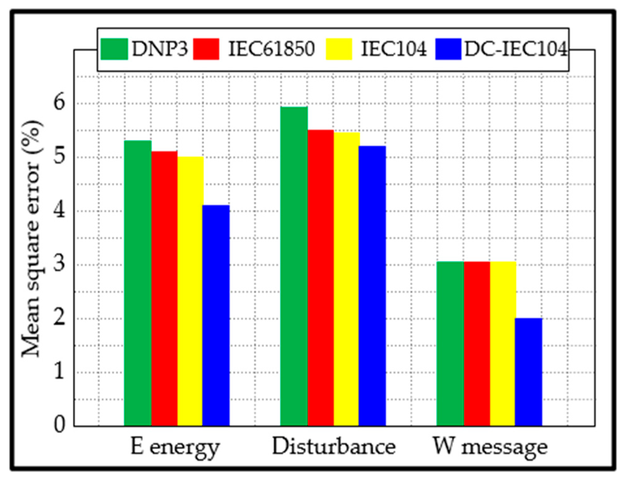
- The average MSE of our approach is 3.78%, while those of DNP3, IEC61850, and IEC104 are 4.74%, 4.53%, and 4.50%, respectively.
- The data release time for disturbance using DNP3 was slightly better than that of our approach. This may be because DNP3 performs very well in transmitting a larger amount of data (but few data packets) over longer distances, compared with our approach, which transmits a high number of small data packets.
- With the exception of the data release time for disturbance, our approach has a better consumption time.
- The proposed approach ensures that data from each monitoring device only enters the appropriate subunit.
- The proposed approach directs and observes how commands are executed in the actuator.
- The proposed approach guarantees that the commands produce effects that ultimately correct the anomalies measured by the sensors.
- It can independently make corrections based on the choices made by the servo application layer.
- The OC returns data to complete the sending of an APDU response upon receiving the data (release request) and returning the equivalent data (release response). If APDU chaining is employed, the final APDU response of a chain is obtained.
- A value set to ‘FFFF’ indicates that the data management unit can send almost any quantity of data. The OC may suggest a suitable value for this scenario.
6.1. Evaluation Protocol
6.2. Performance Comparison
7. Discussion
7.1. Comparative Discussion
7.2. Discussion on Weaknesses and Challenges
- Online invasions may result from inadequate encryption and authentication. Monitoring devices/sensors may be susceptible to hacking due to the lack of adequate security mechanisms. Infected IoT nodes can jeopardize the integrity of the entire smart structure. Cybercriminals can invade IoT networks, rendering smart structures unusable. Therefore, to avoid such malicious attacks, adequate encryption and authentication must be performed.
- Over time, we know that the number of devices could increase, which will also increase the connection; the need for data transmission and storage will increase accordingly. New communication protocols can be used for this purpose; moreover, edge computing and cloud infrastructure must adapt to increasing data loads.
- Patching must be performed frequently to prevent security lapses. Long-term operation, especially in isolated or maritime environments, depends on effective energy management. Therefore, the use of artificial intelligence-based analysis will be significant for optimizing maintenance cycles and predicting malfunctions.
- We have noticed that during summer, the monitoring devices/sensors heat up so much that they are subject to crashing. Therefore, we designed a microcontroller that can reset the service while saving data when it crashes [54]. However, it is important to always regulate the temperature of the control room where the monitoring devices/sensors are placed so that they are free from overheating.
8. Conclusions and Future Work
- We need to add an extra layer since the Servo Application Layer is saturated with multiple modules and units. This will allow the system to avoid clutter, improve data processing, and reduce the release time.
- We will consider including new types of information sources, such as images of submarine cables captured at sea. This will allow us to obtain graphical information on all the cables so that, in addition to the technical information code, the graphic image can also be released on the appropriate platform.
- The application of the measure unit through its commands produces effects that can correct the abnormality measured by the sensors. In addition, the OC can take autonomous corrective measures. However, these measures are sometimes not the most effective. Thus, we must continue to work on finding a solution to this problem.
- The points mentioned in the Discussion section will be considered to improve the operation of our system in terms of security, scalability, and maintenance.
Author Contributions
Funding
Institutional Review Board Statement
Data Availability Statement
Acknowledgments
Conflicts of Interest
Appendix A

| Configuration Information | Parameter | Interpretation |
|---|---|---|
| TypeID | 9 | The type identifier is a normalized telemetry value |
| InformationObjectAddress | 1 | The information object address is 1 |
| Quantity | 1 | The number of messages is 1 |
| TransmitionCause | 20 | The reason for the transmission is a response station call |
| TransmissionTime | 60 | The transmission frequency is 60 |
| CommonAddress | 1 | The public address is 1 |
| Message | Message Explanation |
|---|---|
| 68 | Initiate |
| 10 | Length |
| 0600 | Send sequence number |
| 0200 | Receive the serial number |
| 09 | Type ID 9, telemetry with quality description |
| 01 | Variable structure qualifier, a telemetry data |
| 1400 | Transmission reason 14, response to total call |
| 0100 | Public address |
| 01000 | Information object address, starting from 0x0001 telemetry number 0 |
| a110 | The telemetry value is 10a1 |
| 00 | Quality descriptor |
| Class of Data | Forces | Frequencies |
|---|---|---|
| First class of data | 0.00 N | 0 to 10,000 kHz |
| 5.00 N | … | |
| … | … | |
| … | … | |
| 16.00 N | 0 to 10,000 kHz | |
| Second class of data | 17.00 N | 0 to 10,000 kHz |
| 20.00 N | … | |
| … | … | |
| … | … | |
| 58.00 N | 0 to 10,000 kHz | |
| Third class of data | 59.00 N | 0 to 10,000 kHz |
| 70.00 N | … | |
| … | … | |
| … | … | |
| 100.00 N | 0 to 10,000 kHz |
| Configuration Information | Parameter | Interpretation |
|---|---|---|
| TypeID | 125 | The type is identified as file segment transfer |
| TransmitionCause | 13 | The reason for the transfer is file transfer |
| CommonAddress | 1 | The public address is 1 |
| Information ObjectAddress | 0 | The information object address is 0 |
| FileName | 1 | The file name is 1, temperature file |
| FileLength | 150 | The file length is 750 KB |
| SectionName | 1 | The section name is 1 |
| SectionLength | 7680 | The length of the section is 7680 B |
| SegmentLength | 120 | The segment length is 120 B |
| TransmissionTime | 60 | The transmission frequency is 60 |
| Message | Message Explanation |
|---|---|
| 68 | Initiate |
| 12 | Length |
| 0600 | Send sequence number |
| 0200 | Receive the serial number |
| 7d | The type identifies 7d, segment |
| 01 | Variable structure qualifier |
| 0d00 | Transfer reason, file transfer |
| 0100 | Public address |
| 000000 | The address of the information object |
| 0110 | File name, temperature data file |
| 01 | Section name |
| 78 | Segment length |
| 01 | Segment |
| Joint | Key 1 | Key 2 |
|---|---|---|
| Total system configuration | Number of clients | Number of AIS devices |
| AIS equipment No. 1 | Device serial port number | AIS MMSI number |
| AIS equipment No. 2 | Device serial port number | AIS MMSI number |
| Client 1 | IP address | IP port number |
| Client 2 | IP address | IP port number |
| Message Type | Message Type Number | Remarks |
|---|---|---|
| Broadcast binary message | Message 8 | It can send both Chinese and English |
| Broadcast security message | Message 14 | It can only send English |
| Addressing binary messages | Message 6 | It can send both Chinese and English |
| Addressing security messages | Message 12 | It can only send Chinese |

| Input Current (A) | 100 | 200 | 300 | 400 | 500 | 600 | 700 | 800 | 900 | 1000 |
| Original fiber temperature (°C) | 16.602 | 16.980 | 17.609 | 18.491 | 19.625 | 21.011 | 22.648 | 24.609 | 26.679 | 29.073 |
| Technical Pointers | Parameter Value |
|---|---|
| Number of ships handled by the server per unit of time | 50 ships |
| Decoding accuracy of the unit time of the acquisition module | 98% |
| Acquisition module receiving/time unit the number of ships | 49 ships |
| The server handles the correct rate of the ship per unit of time | 98% |
| AIS package analysis shows a delay | 10 ms |
| Short message system response delay | 10 ms |
| Historical data query response delay | 10 ms |
| Number of ships per unit time | 38 ships |
References
- Khanna, A.; Kaur, S. Evolution of Internet of Things (IoT) and its significant impact in the field of Precision Agriculture. Comput. Electron. Agric. 2019, 157, 218–231. [Google Scholar] [CrossRef]
- Kamilaris, A.; Kartakoullis, A.; Prenafeta-Boldú, F.X. A review on the practice of big data analysis in agriculture. Comput. Electron. Agric. 2017, 143, 23–37. [Google Scholar] [CrossRef]
- Lin, B.; Tan, Q.; Zhang, G.; Zhang, L.; Wang, Y.; Xiong, J. Temperature and Pressure Composite Measurement System Based on Wireless Passive LC Sensor. IEEE Trans. Instrum. Meas. 2020, 70, 9502811. [Google Scholar] [CrossRef]
- Shafique, K.; Khawaja, B.A.; Sabir, F.; Qazi, S.; Mustaqim, M. Internet of Things (IoT) for Next-Generation Smart Systems: A Review of Current Challenges, Future Trends and Prospects for Emerging 5G-IoT Scenarios. IEEE Access 2020, 8, 23022–23040. [Google Scholar] [CrossRef]
- Morabito, R.; Cozzolino, V.; Ding, A.Y.; Beijar, N.; Ott, J. Consolidate IoT Edge Computing with Lightweight Virtualization. IEEE Netw. 2018, 32, 102–111. [Google Scholar] [CrossRef]
- Relion® Protection and Control. REX640 IEC 60870-5-104 Communication Protocol Manual. 2023, pp. 35–57. Available online: www.abb.com/mediumvoltage (accessed on 1 April 2024).
- Jadhav, A.R.; Kiran, S.; Pachamuthu, R. Development of a Novel IoT-Enabled Power-Monitoring Architecture With Real-Time Data Visualization for Use in Domestic and Industrial Scenarios. IEEE Trans. Instrum. Meas. 2020, 70, 1002314. [Google Scholar] [CrossRef]
- Vijayalakshmi, V.; Saravanan, M. An Extensive Analysis of Task Scheduling Algorithms Based on Fog Computing Qos Metrics. In Proceedings of the 2022 International Conference on Innovative Computing, Intelligent Communication and Smart Electrical Systems (ICSES), Chennai, India, 15–16 July 2022. [Google Scholar] [CrossRef]
- Fortino, G.; Messina, F.; Rosaci, D.; Sarné, G.M.L.; Savaglio, C. A Trust-Based Team Formation Framework for Mobile Intelligence in Smart Factories. IEEE Trans. Ind. Inform. 2020, 16, 6133–6142. [Google Scholar] [CrossRef]
- Zhong, R.Y.; Xu, X.; Klotz, E.; Newman, S.T. Intelligent manufacturing in the context of industry 4.0: A review. Engineering 2017, 5, 616–630. [Google Scholar] [CrossRef]
- Xu, X.; Han, M.; Nagarajan, S.M.; Anandhan, P. Industrial Internet of Things for smart manufacturing applications using hierarchical trustful resource assignment. Comput. Commun. 2020, 160, 423–430. [Google Scholar] [CrossRef]
- Durana, P.; Perkins, N.; Valaskova, K. Artificial intelligence data-driven internet of things systems, real-time advanced analytics, and cyber-physical production networks in sustainable smart manufacturing. Econ. Manag. Financ 2021, 16, 20–30. [Google Scholar] [CrossRef]
- Stergiou, C.L.; Psannis, K.E.; Gupta, B.B. IoT-Based Big Data Secure Management in the Fog Over a 6G Wireless Network. IEEE Internet Things J. 2020, 8, 5164–5171. [Google Scholar] [CrossRef]
- Al-Qerem, A.; Alauthman, M.; Almomani, A.; Gupta, B. Iot transaction processing through cooperative concurrency control on fog-cloud computing environment. Soft Comput. 2019, 24, 5695–5711. [Google Scholar] [CrossRef]
- Li, D.; Deng, L.; Gupta, B.B.; Wang, H.; Choi, C. A novel CNN based security guaranteed image watermarking generation scenario for smart city applications. Inform. Sci. 2019, 479, 432–447. [Google Scholar] [CrossRef]
- Di Renzone, G.; Fort, A.; Mugnaini, M.; Pozzebon, A.; Vignoli, V. Data Transmission from ATEX Boxes by Means of LoRa Technology for Industrial Internet of Things (IIoT) Applications. In Proceedings of the 2021 IEEE International Instrumentation and Measurement Technology Conference (I2MTC), Glasgow, UK, 17–20 May 2021. [Google Scholar] [CrossRef]
- Gao, J.G.; Chen, H.; Liu, W.; Cheng, B.; Zhang, C.T. Key Technology of Passive Wireless Temperature Measurement of Power High-Voltage Switchgear Based on Wireless Sensor Network. In Proceedings of the 2022 IEEE Conference on Telecommunications, Optics and Computer Science (TOCS), Dalian, China, 11–12 December 2022. [Google Scholar] [CrossRef]
- Manuel, E.M.; Pankajakshan, V.; Mohan, M.T. Efficient Strategies for Signal Aggregation in Low-Power Wireless Sensor Networks With Discrete Transmission Ranges. IEEE Sens. Lett. 2023, 7, 7500304. [Google Scholar] [CrossRef]
- Khriji, S.; Kallel, A.Y.; Reedy, S.; El Houssaini, D.; Kammoun, I.; Kanoun, O. Dynamic Autonomous Energy Consumption Measurement for a Wireless Sensor Node. In Proceedings of the 2019 IEEE International Symposium on Measurements & Networking (M&N), Catania, Italy, 8–10 July 2019. [Google Scholar] [CrossRef]
- Al-Zaidi, R.; Woods, J.C.; Al-Khalidi, M.; Hu, H. Building novel vhf-based wireless sensor networks for the Internet of Marine Things. IEEE Sens. J. 2018, 18, 2131–2144. [Google Scholar] [CrossRef]
- Zhao, C.; Wang, X.; Liu, X.; Zhang, S.; Wang, H. A small buoy for flux measurement in air-sea boundary layer. In Proceedings of the 2017 13th IEEE International Conference on Electronic Measurement & Instruments (ICEMI), Yangzhou, China, 20–22 October 2017. [Google Scholar] [CrossRef]
- Huang, H.; Zhang, S.; Wang, D.; Ling, K.-V.; Liu, F.; He, X. A Novel Bayesian-Based Adaptive Algorithm Applied to Unobservable Sensor Measurement Information Loss for Underwater Navigation. IEEE Trans. Instrum. Meas. 2023, 72, 9514812. [Google Scholar] [CrossRef]
- Chen, H.; Chen, H.; Wang, K. Temporal tracking of ocean current field using the underwater acoustic sensor network. In Proceedings of the 2018 OCEANS—MTS/IEEE Kobe Techno-Oceans, Kobe, Japan, 28–31 May 2018; Institute of Electrical and Electronics Engineers Inc.: Kobe, Japan, 2018. [Google Scholar]
- DL/T5104-2009; Telecontrol Equipment and Systems. Part 5-104: Transmission Protocols-Network Access for IEC 60870-5-101 Using Standard Transport Profiles. Standardization Administration of China: Beijing, China, 2017. Available online: https://www.chinesestandard.net/.../DLT634.5104-2009 (accessed on 1 April 2024).
- GBT18657.5-2002; Telecontrol Equipment and Systems. Part 5: Transmission Protocol, Chapter 5: Basic Application Functions. Standardization Administration of China: Beijing, China, 2002. Available online: https://www.chinesestandard.net/.../GBT18657.5-2002 (accessed on 1 April 2024).
- GBT18657.4-2002; Telecontrol Equipment and Systems—Part 5: Transmission Protocols—Section 4: Definition and Coding of Application Information Elements. Standardization Administration of China: Beijing, China, 2023. Available online: https://www.chinesestandard.net/.../GBT18657.4-2002 (accessed on 1 April 2024).
- DL/T634.5101-2002; Telecontrol Equipment and Systems. Part 5: Transmission Protocols. Section 101: Companion Standard for Basic Telecontrol Tasks (IEC 60870-5-101: 2002, IDT). Standardization Administration of China: Beijing, China, 2023. Available online: https://www.chinesestandard.net/.../DLT634.5101-2002 (accessed on 1 April 2024).
- Long, D.U.; Shi, L.N. Application of IEC60870-5-104 telecontrol protocol based on TCP/IP in direct dispatching station. Power Syst. Prot. Control. 2008, 36, 51–55. [Google Scholar] [CrossRef]
- Musil, P.; Mlynek, P. Overview of Communication Scenarios for IEC 60870-5-104 Substation Model. In Proceedings of the 2020 21st International Scientific Conference on Electric Power Engineering (EPE), Prague, Czech Republic, 19–21 October 2020. [Google Scholar] [CrossRef]
- Sun, J.N.; Liu, M.Z.; Xu, A.D.; Guo, T.T.; Han, X.J. Design and implementation of PLC communication module based on IEC60870-5-104 telecontrol protocol. High Technol. Commun. 2016, 26, 389–395. [Google Scholar] [CrossRef]
- Tao, X.J.; Xu, F.Y.; Wang, Y.L. Application of IEC 60870-5-104 protocol in photovoltaic power station. Mech. Electr. Eng. Technol. 2014, 43, 40–44. [Google Scholar]
- Zhu, C.; Li, B.N.; Lv, Z.Y.; Zhao, X.Y. Design and Implementation of the Substation Intelligent Auxiliary Control System Based on OPC UA. In Proceedings of the 5th International Conference on Renewable Energy and Power Engineering (REPE), Beijing, China, 28–30 September 2022. [Google Scholar] [CrossRef]
- Le, Z.C.; Xu, Q.; Wang, Y.N.; Hao, G.W.; Pan, W.F.; Sun, Y.L.; Qian, Y.W. On Joint Optimization of UAV-Assisted Covert Communication Systems with NOMA for Hydropower Internet of Things. Drones 2023, 7, 610. [Google Scholar] [CrossRef]
- Leens, F. An introduction to i2c and SPI protocols. IEEE Instrum. Meas. Mag. 2009, 12, 8–13. [Google Scholar] [CrossRef]
- Fouda, B.M.T.; Yang, B.; Han, D.Z.; An, B.W. Pattern Recognition of Optical Fiber Vibration Signal of the Submarine Cable for Its Safety. IEEE Sen. J. 2021, 21, 6510–6519. [Google Scholar] [CrossRef]
- Motil, A.; Bergman, A.; Tur, M. [INVITED] State of the art of Brillouin fiber-optic distributed sensing. Opt. Laser Technol. 2016, 78, 81–103. [Google Scholar] [CrossRef]
- Tabi Fouda, B.M.; Edima-Durand, H.C.; Atangana, J.; Zhang, W. Research of a New Technique to Improve Temperature Measurements in the BOTDA Fiber Sensor. IEEE Sens. J. 2024, 24, 40939–40951. [Google Scholar] [CrossRef]
- Holm, H.; Mellegård, N. Fast Decoding of Automatic Identification Systems (AIS) Data. In Proceedings of the Conference: Computer and IT Applications in the Maritime Industries, Pavone, Italy, 13 May 2018. [Google Scholar]
- Ma, S.X.; Wang, J.; Meng, X.; Wang, J.F. A Vessel Positioning Algorithm Based on Satellite Automatic Identification System. J. Electr. Comput. Eng. 2017, 2017, 8097187. [Google Scholar] [CrossRef]
- Berger, S.; Druckenbrod, M.; Pergande, M.M.; Abdel-Maksoud, M. A two-stage optimisation method for full-scale marine propellers working behind a ship. Ship Technol. Res. 2015, 61, 64–79. [Google Scholar] [CrossRef]
- Fouda, B.M.T.; Yang, B.; Han, D.Z.; An, B.W. A Hybrid Model Integrating MPSE and IGNN for Events Recognition along Submarine Cables. IEEE Trans. Instrum. Meas. 2022, 71, 6502913. [Google Scholar] [CrossRef]
- Fouda, B.M.T.; Han, D.Z.; Zhang, W.J.; An, B.W. Research on key technology to determine the exact maximum allowable current-carrying ampacity for submarine cables. Opt. Laser Technol. 2024, 175, 110705. [Google Scholar] [CrossRef]
- Fouda, B.M.T.; Han, D.Z.; An, B.W.; Chen, X.Z.; Shen, S.X. Design and Implementation of Software for Ship Monitoring System in Offshore Wind Farms. Model. Simul. Eng. 2019, 2019, 3430548. [Google Scholar] [CrossRef]
- Fouda, B.M.T.; Zhang, W.J.; Han, D.Z.; An, B.W. Research on Key Factors to Determine the Corrected Ampacity of Multicore Photoelectric Composite Cables. IEEE Sens. J. 2024, 24, 7868–7880. [Google Scholar] [CrossRef]
- LibreTexts. Solving Systems of Nonlinear Equations. 2022. Available online: https://math.libretexts.org/Bookshelves (accessed on 1 April 2024).
- Dong, Y.K. Ultra-fast distributed Brillouin optical fiber sensing for dynamic strain measurement. In Proceedings of the International Photonics and Opto-Electronics Meeting 2019 (OFDA, OEDI, ISST, PE, LST, TSA), Wuhan, China, 11–14 November 2019. [Google Scholar] [CrossRef]
- ITU-R M.1371-5; Technical Characteristics of Automatic Identification Systems Using Time Division Multiple Access in the VHF Maritime Mobile Frequency Band. International Telecommunication Union (ITU), ITU-R: Geneva, Switzerland, 2014.
- Wang, X.Y.; Zhang, S.F. Evaluation of multipath signal loss for AIS signals transmitted on the sea surface. Ocean. Eng. 2017, 146, 9–20. [Google Scholar] [CrossRef]
- Tabi Fouda, B.M.; Zhang, W.; Atangana, J.; Edima-Durand, H.C. Development of a Key Method for the Optimization of Port Vessel Detection Based on an Improved Multi-Structural Morphology Approach. J. Mar. Sci. Eng. 2024, 12, 1969. [Google Scholar] [CrossRef]
- Tabi Fouda, B.M.; Wang, L.; Zhang, W.; Atangana, J. Phase-Sensitive Optical Time-Domain Reflectometry-Based Audio Excitation Signal Demodulation and Reproduction. IEEE Trans. Instrum. Meas. 2025, 74, 7001414. [Google Scholar] [CrossRef]
- Shen, H.; Li, J.; Wu, G.; Zhang, M. Data release for machine learning via correlated differential privacy. Inf. Process. Manag. 2023, 60, 103349. [Google Scholar] [CrossRef]
- Wang, J.; Palanisamy, B. Securing Blockchain-based Timed Data Release against Adversarial Attacks. J. Comput. Secur. 2021, 1, 649–677. [Google Scholar]
- Ye, H.; Liu, J.; Wang, W.; Li, P.; Li, T.; Li, J. Secure and efficient outsourcing differential privacy data release scheme in Cyber–physical system. Future Gener. Comput. Syst. 2020, 108, 1314–1323. [Google Scholar] [CrossRef]
- Fouda, B.M.T.; Han, D.Z.; An, B.W. Microcontroller design for security system: Implementation of a microcontroller based on STM32F103 microchip. Int. J. Embed. Syst. 2019, 11, 541–550. [Google Scholar]




| Hardware | Memory | 16 GB RAM |
| CPU | Intel(R) Xeon® E5-2620 v3 @ 2.40 GHz 2.40 GHz (Anxin Information Technology Co., Ltd., Shanghai, China) | |
| Software | Library | API |
| Programming Language | Matlab R2016a (8.3.0.532) and LabWindows/CVI | |
| Operating System | Window 10 |
| Amount of Data | Amount of Data | |
|---|---|---|
| Simple Data | Complex Data | |
| Small amount of data | Electric energy, equipment status | Alarm, AIS |
| Big amount of data | Temperature, strain, disturbance | - |
| Information Object Name | Corresponding Address (Hex) | Amount of Information | Table | Field | Data Type |
|---|---|---|---|---|---|
| Electrical energy | 000001H~005000H | 20,480 | Current | Electrical energy | Floating-point |
| Cladding monitoring | 005001H~00A000H | 20,480 | Protective Layer | Cladding monitoring | Floating-point |
| Device status | 00A001H~00A200H | 512 | State | Device status | Integer |
| File Section Name | Information Object |
|---|---|
| 1 | Temperature |
| 2 | Strain |
| 3 | Disturbance |
| 4 | Alarm |
| 5 | AIS |
| - | - |
| Message Type (Decimal) | Message Semantics | Encode |
|---|---|---|
| 120 | The file is ready | F_FR_NA_1 |
| 121 | The section is ready | F_SR_NA_1 |
| 122 | Summon directory, select file, summon file, summon section | F_FC_NA_1 |
| 123 | Final section, last paragraph | F_LS_NA_1 |
| 124 | Confirm the file, confirm the section | F_AF_NA_1 |
| 125 | Segment | F_SG_NA_1 |
| 126 | Directory | F_DR_NA_1 |
| 127 | Retain | - |
| ASDU Definition | Number of Bytes |
|---|---|
| Type Identification (TYP) | 1 |
| Variable Structure Qualifier (VSQ) | 1 |
| Reason for transmission (COT) | 2 |
| ASDU Public Address (CA) | 2 |
| Information Object Address (IOA) | 3 |
| File name or subdirectory name (NOF) | 2 |
| File length (LOF) | 3 |
| Status of the file (SOF) | 1 |
| File creation time (CP56Time2a) | 7 |
| ASDU Definition | Number of Bytes |
|---|---|
| Type Identification (TYP) | 1 |
| Variable Structure Qualifier (VSQ) | 1 |
| Reason for transmission (COT) | 2 |
| ASDU Public Address (CA) | 2 |
| Information Object Address (IOA) | 3 |
| File name (NOF) | 2 |
| Section Name (NOS) | 1 |
| Length of segment (LOS) | 1 |
| Segment | n |
| AIS Data Information | Data Type | Number of Bytes |
|---|---|---|
| MMSI Identifier | String | 9 |
| Device type | String | 1 |
| Name of the ship | String | 10 |
| Longitude | Floating-point | 4 |
| Latitude | Floating-point | 4 |
| Name of the nearest submarine cable | String | 10 |
| Nearest submarine cable distance | Floating-point | 4 |
| Speed | Floating-point | 4 |
| Course | Floating-point | 4 |
| AIS Data Information | Data Type | Number of Bytes |
|---|---|---|
| Alarm number | Integer | 4 |
| Alarm time | String | 20 |
| Submarine cable number | Integer | 4 |
| Cable details | String | 10 |
| Start position | Floating-point | 4 |
| End position | Floating-point | 4 |
| Alarm code | Integer | 4 |
| Alarm details | String | 20 |
| Processing status | String | 10 |
| Approaches | ||||
|---|---|---|---|---|
| Mean Square Error (%) | Using DNP3 | Using IEC61850 | Using IEC 104 | Using DC-IEC 104 |
| Electrical energy | 5.23 | 5.02 | 5.00 | 4.11 |
| Disturbance | 5.93 | 5.51 | 5.49 | 5.27 |
| Ships positioning | 3.06 | 3.06 | 3.06 | 1.99 |
| Approaches | ||||
|---|---|---|---|---|
| Time Consumption (s) | Using DNP3 | Using IEC61850 | Using IEC 104 | Using DC-IEC 104 |
| Electrical energy | 1.771 | 1.104 | 1.108 | 1.103 |
| Disturbance | 1.106 | 1.245 | 1.149 | 1.149 |
| Ships positioning | 1.315 | 1.123 | 1.113 | 1.110 |
| Approaches | ||||
|---|---|---|---|---|
| Characteristics | Using DNP3 | Using IEC61850 | Using IEC 104 | Using DC-IEC 104 |
| Number of data released | 245 | 244 | 243 | 245 |
| Number of false positive | 2 | 0 | 1 | 0 |
| Number of unreleased data | 5 | 6 | 7 | 5 |
| False data release rate | 0.47 | 0.045 | 0.045 | 0.037 |
| Average precision | 0.879 | 0.898 | 0.883 | 0.902 |
| Average recall | 0.888 | 0.909 | 0.913 | 0.987 |
| Average F-score | 0.923 | 0.941 | 0.921 | 0.951 |
| Average processing time | 1.398 s | 1.124 s | 1.090 s | 1.083 s |
| Characteristics | Approaches | ||||
|---|---|---|---|---|---|
| AP.1 | AP.2 | AP.3 | DC-IEC104 | ||
| Security | √ | √ | √ | × | |
| Scalability | √ | √ | √ | × | |
| Maintenance | √ | √ | √ | × | |
| Spring (10 °C~25 °C) | Number of data | 50 | 50 | 50 | 50 |
| Precision | 90.17% | 89.94% | 90.11% | 91.29% | |
| Error rate | 2.52% | 4.76% | 4.34% | 2.21% | |
| Processing time | 1.371 s | 0.988 s | 2.336 s | 1.083 s | |
| Remark | Regular | Regular | Regular | Regular | |
| Summer (26 °C~31 °C) | Number of data | 50 | 50 | 50 | 50 |
| Precision | 90.17% | 89.94% | 90.11% | 88.73% | |
| Error rate | 2.52% | 4.76% | 4.34% | 4.33% | |
| Processing time | 1.371 s | 0.988 s | 2.336 s | 1.174 s | |
| Remark | Regular | Regular | Regular | Regular | |
| Autumn (16 °C~24 °C) | Number of data | 50 | 50 | 50 | 50 |
| Precision | 90.17% | 89.94% | 90.11% | 91.29% | |
| Error rate | 2.52% | 4.76% | 4.34% | 2.21% | |
| Processing time | 1.371 s | 0.988 s | 2.336 s | 1.083 s | |
| Remark | Regular | Regular | Regular | Regular | |
| Winter (−4 °C~11 °C) | Number of data | 50 | 50 | 50 | 50 |
| Precision | 90.17% | 89.94% | 90.11% | 91.29% | |
| Error rate | 2.52% | 4.76% | 4.34% | 2.21% | |
| Processing time | 1.371 s | 0.988 s | 2.336 s | 1.083 s | |
| Remark | Regular | Regular | Regular | Regular | |
Disclaimer/Publisher’s Note: The statements, opinions and data contained in all publications are solely those of the individual author(s) and contributor(s) and not of MDPI and/or the editor(s). MDPI and/or the editor(s) disclaim responsibility for any injury to people or property resulting from any ideas, methods, instructions or products referred to in the content. |
© 2025 by the authors. Licensee MDPI, Basel, Switzerland. This article is an open access article distributed under the terms and conditions of the Creative Commons Attribution (CC BY) license (https://creativecommons.org/licenses/by/4.0/).
Share and Cite
Tabi Fouda, B.M.; Wang, L.; Han, D.; Ngoumou, P.C.; Atangana, J. Design and Implementation of a Novel IoT Architecture for Data Release System Between Multiple Platforms: Case of Smart Offshores. Sensors 2025, 25, 3384. https://doi.org/10.3390/s25113384
Tabi Fouda BM, Wang L, Han D, Ngoumou PC, Atangana J. Design and Implementation of a Novel IoT Architecture for Data Release System Between Multiple Platforms: Case of Smart Offshores. Sensors. 2025; 25(11):3384. https://doi.org/10.3390/s25113384
Chicago/Turabian StyleTabi Fouda, Bernard Marie, Lei Wang, Dezhi Han, Paul Claude Ngoumou, and Jacques Atangana. 2025. "Design and Implementation of a Novel IoT Architecture for Data Release System Between Multiple Platforms: Case of Smart Offshores" Sensors 25, no. 11: 3384. https://doi.org/10.3390/s25113384
APA StyleTabi Fouda, B. M., Wang, L., Han, D., Ngoumou, P. C., & Atangana, J. (2025). Design and Implementation of a Novel IoT Architecture for Data Release System Between Multiple Platforms: Case of Smart Offshores. Sensors, 25(11), 3384. https://doi.org/10.3390/s25113384


