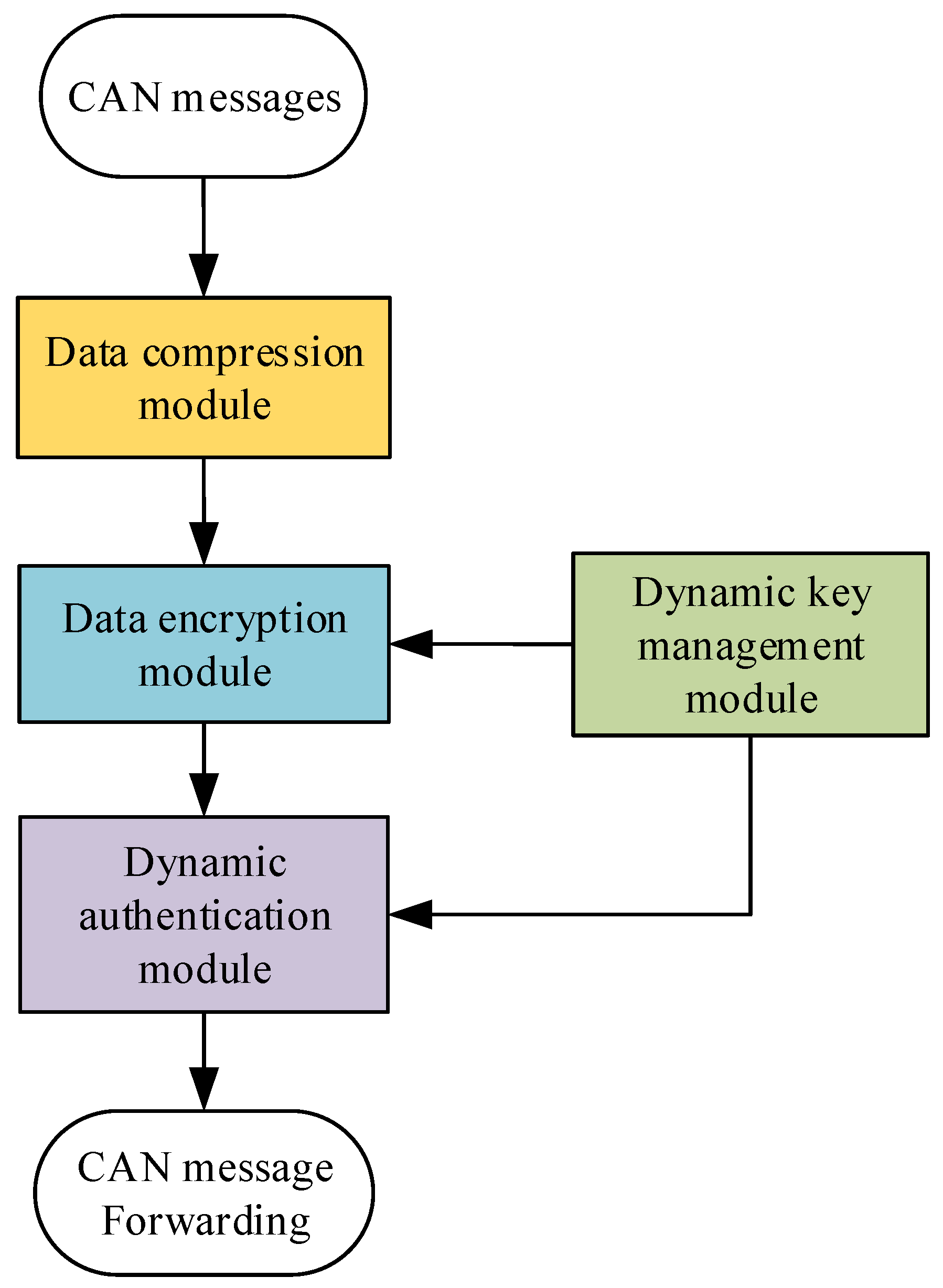
3.2.1. Data Encryption Module
Under the current conditions, cracking a 16-byte AES-128 encryption would take billions of years at the very least. Therefore, in the encryption module, we have adopted the AES-128 encryption algorithm. The plaintext data come from the sorting results generated by the compression module from the previous round, and the key is dynamically generated and provided by the key-update module. The compressed message output by the compression module is then XORed with the encrypted data generated by the encryption module, resulting in the final encrypted output. This design not only ensures the efficiency and security of data encryption but also significantly improves the system’s resistance to attacks by applying dynamic keys.
The plaintext is provided by the sorted order (
sorted_order) generated by the compression module. The key is the one generated by the dynamic key-update module (
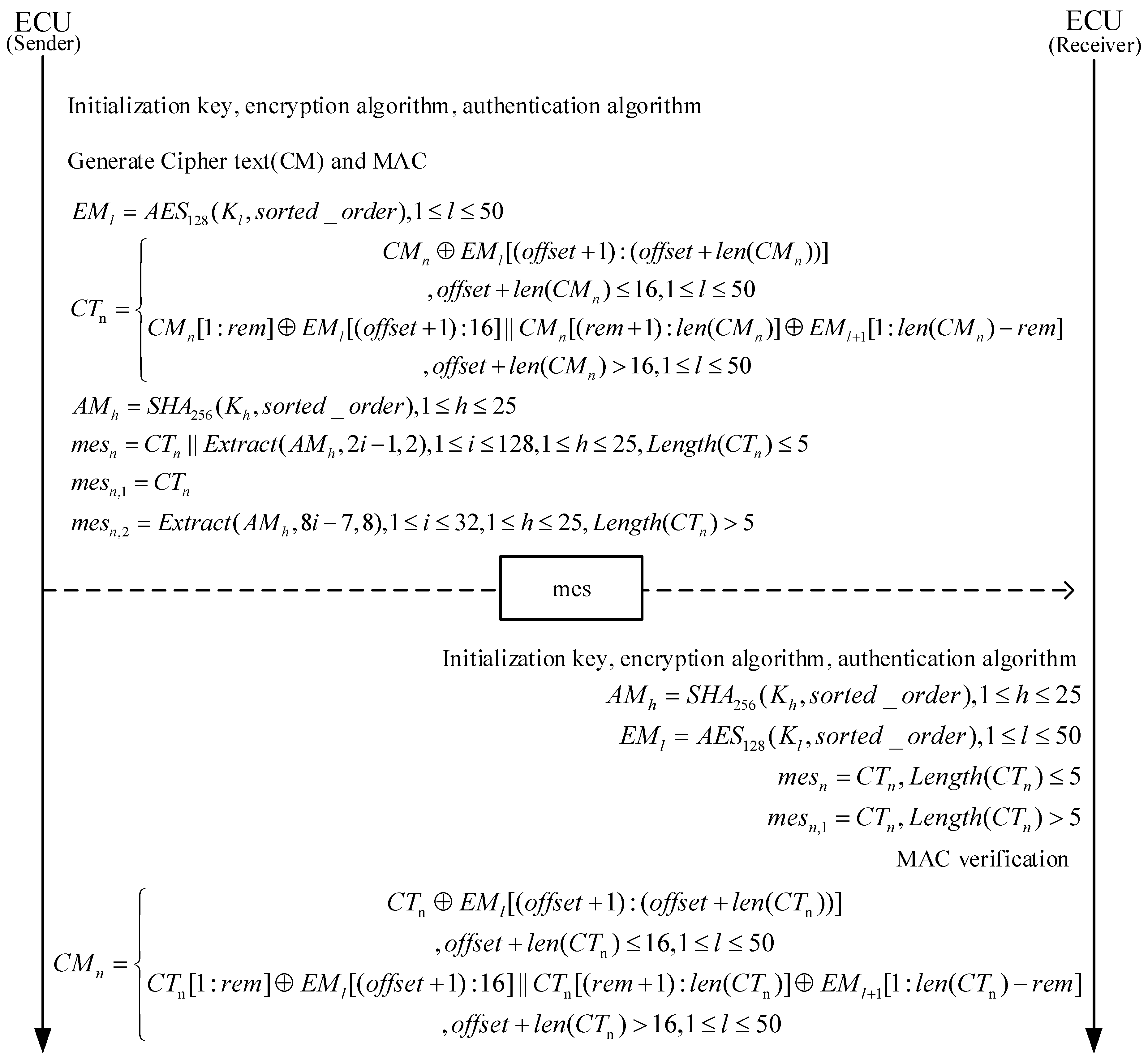
) (the initial keys for both the transmitter and receiver are preloaded by the program developer during system initialization to ensure key consistency between the two ends), and the result of the AES-128 algorithm is denoted as
. The formula is as (10):
Since each round of processing involves 100 messages, we need to plan the message-handling process based on the worst-case scenario. In the worst case, the system needs to generate 50 AES-encrypted messages (considering that the AES-128 encryption algorithm produces 16-byte encrypted data, while our raw data may all be 8 bytes in size). Therefore, the system needs to prepare 50 independent AES encryption keys. Meanwhile, the sorted_order sequence generated by the compression module will be processed as the plaintext data for encryption. During the encryption process, the system will use the l-th key from the key group as the current encryption key.
The length of the compressed message varies, and during each encryption operation, the appropriate number of bytes from the generated are XORed based on the byte size of the compressed message. This method significantly reduces the amount of encryption calculations and the frequency of key updates, improves the overall efficiency, and ensures the security of data.
The final encrypted result is calculated by performing an XOR between the compressed message
and the encryption result
, as shown in (11):
In the encryption process, represents the final encrypted result of the n-th message, denotes the length of the n-th compressed message (in bytes), offset indicates the number of bytes already used in the current (initialized to 0), rem = 16 − offset represents the number of remaining available bytes in the current , and || denotes the concatenation operation. When the remaining bytes in are sufficient to process the entire , we use the first formula in Equation (11) for computation. When the remaining bytes in are insufficient to process the entire , we split into two parts: the first part is XORed with the remaining bytes of , and the second part is XORed with . Finally, the two parts are concatenated to form the final , as described in the second formula of Equation (11).
3.2.2. Data Authentication Module
We use the HMAC-SHA-256 algorithm as the authentication method for the in-vehicle CAN bus network security protocol [
27].
The plaintext data are provided by the sorting result
sorted_order generated by the compression module. The keys are provided by the key group
generated by the dynamic key-update module, where
represents the
h-th key in the key group used for computation. The HMAC-SHA-256 algorithm generates 32 bytes of authentication data in a single operation. In the worst-case scenario of processing 100 messages (assuming each message is 8 bytes in size), we need a maximum of 25 keys to generate 25 MAC authentication data. The result generated by the algorithm
is shown in Formula (12):
Since the maximum data-frame length of the CAN bus is 8 bytes, the authentication data must also adhere to this limit. To improve the efficiency of the authentication process and meet real-time requirements, we have designed a dynamic identity authentication mechanism that adapts to the CAN bus data transmission rate.
Authentication efficiency analysis: The time
T required to perform a brute-force attack on the standard CAN bus access is shown in Equation (13).
where
B is the number of bits of authentication code,
R is the transmission rate of the CAN bus, and
F is the maximum number of bits that can be transmitted in one frame. If the rate of the CAN bus is 1 Mbps, it will take 8.39 s to brute force the authentication code of 2 bytes after sending a message with a 128-bit frame including bit stuffing. If the authentication code selects 1 byte under the same conditions, the brute-force attack time is 0.0327 s. Therefore, we choose the authentication code of 2 or more bytes to be placed in the redundant position after encryption, which improves the security and does not need to place the authentication code on the CRC and extended ID to cause the normal work of CRC like [
16,
27].
We balance real-time performance and security by using two different methods to load the authentication code, depending on the size of the compressed and encrypted data:
When the size of the compressed and encrypted data is less than or equal to 5 bytes, we choose to place a 2-byte authentication code in the redundant position of the encrypted data. Our goal is to differentiate between compressed and uncompressed information, and we have selected 5 bytes as the threshold. By adding a 2-byte authentication code to the compressed message, it is possible to send both the encrypted and authenticated message within a single frame. This not only effectively enhances security but also avoids the serious issues that might arise from placing the authentication code in the CRC or extended ID.
The formula for the final message
mes is as (14):
Here, Extract is the extraction function. Since each operation only requires extracting 2 bytes of authentication code from the 256-bit (32-byte) data of and appending it to to form the final message, and the extraction index i ranges from 1 to 128. The extraction process starts from , where 2i − 1 is the starting position for extraction, and 2 indicates the length of extraction (i.e., 2 bytes). When all 256 bits of are used, the system continues to extract bytes from for authentication purposes, and so on.
When the compressed and encrypted message size is greater than 5 bytes, to ensure the CAN bus frame’s transmission safety, we send two frames. The first frame is the 8-byte encrypted message. The second frame contains the 8-byte authentication code.
The formula for the final message is as (15):
Here, Extract is the extraction function. Since in this case we need to extract 8 bytes of authentication code from the 256-byte data of , the extraction index i ranges from 1 to 32. The extraction process starts from , where 8i − 7 is the starting position for extraction, and 8 indicates the length of extraction (i.e., 8 bytes). When all 256 bytes of are used, the system continues to extract bytes from for authentication purposes, and so on.
3.2.3. Dynamic Key Management Module
The AES algorithm is a symmetric encryption technology that requires both plaintext and a key for its operation. Similarly, HMAC operations also necessitate the involvement of a key. Therefore, the storage and protection of keys are central to ensuring the overall security of the system. In security protocols, the methods of key generation and renewal, as well as how the communicating parties synchronize symmetric keys, are critical points of focus.
In some current security protocols, key updates typically rely on a gateway. This method requires multiple communications between the ECU and the gateway. After receiving the key, the ECU must also calculate the remaining key chain. In practical applications, due to the large number of vehicle ECUs, this approach not only significantly increases the bus load but also wastes the computational resources of the ECUs, thereby reducing the overall efficiency and real-time performance of the system.
Key-Update Mechanism: To address the issues of high key management overhead, slow update speeds, and limited resources in traditional solutions, this paper designs a dynamic key generation, distribution, and management module named DBK (Dynamic Key Generation and Management). The DBK module automatically generates keys through the correct processing of the initially agreed-upon protocol by the sender and receiver, without the need for additional gateway communication support, thereby further reducing the bus load pressure and enhancing system efficiency and real-time performance. The DBK module is based on an LFSR for generating and managing the keys required for encryption and authentication, and its working principle is as follows:
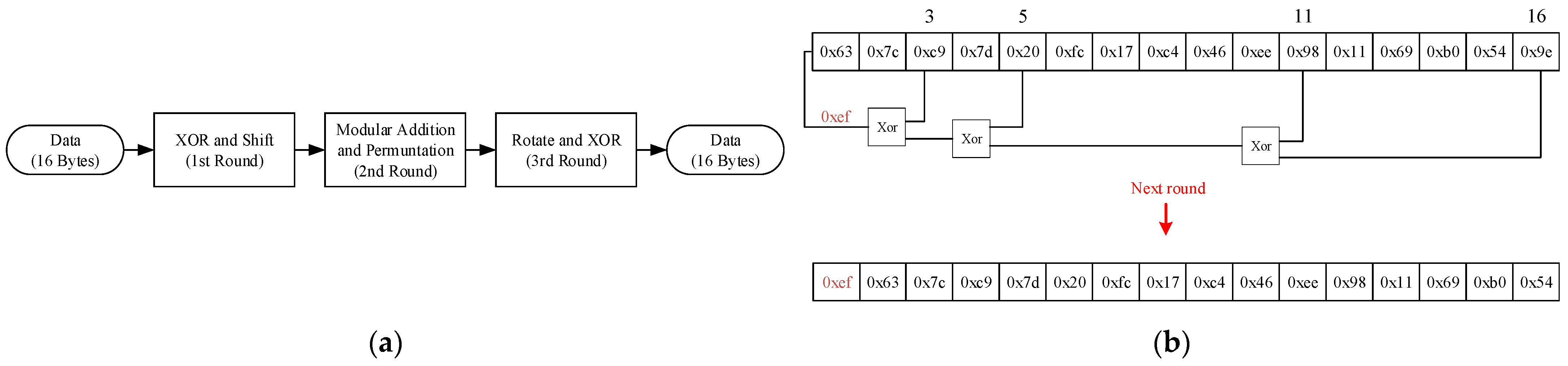
- 1.1.
Initial Key Setup: During each round of key generation, our custom-designed nonlinear function first produces a 16-byte initial key value, as shown in
Figure 5a.
- 1.2.
Dynamic Key Generation: Following predefined security policies, the system selects 4–6 specific bytes (including the least significant byte) to participate in subsequent XOR operations. The 16-byte key is shifted right by one unit as a whole, with the least significant unit being discarded. The pre-selected bytes are then subjected to an XOR operation one by one, and the result is filled into the most significant unit. Each shift generates a new 16-byte key, ultimately forming a key group for dynamic updates, as shown in
Figure 5b.
For example, in
Figure 5, after generating through nonlinear function, the initial key for both the sender and receiver is set to 0x63, 0x7C, 0xC9, 0x7D, 0x20, 0xFC, 0x17, 0x C4, 0x46, 0xEE, 0x98, 0x11, 0x69, 0xB0, 0x54, 0x9E. By selecting the 3rd, 5th, 11th, and 16th byte units for the XOR operation, the result 0xEF is obtained. The new key then becomes 0xEF, 0x63, 0x7C, 0xC9, 0x7D, 0 x20, 0xFC, 0x17, 0xC4, 0x46, 0xEE, 0x98, 0x11, 0x69, 0xB0, 0x54. Through this cyclic process, a key group is generated for encryption and authentication purposes. The DBK module enhances security by pre-configuring the XOR byte selection at the manufacturing stage, eliminating the need to transmit keys alongside data. This approach removes the requirement for a standalone Key Management Unit (KECU), thereby saving ECU memory resources. Additionally, since the keys do not occupy data-frame space, there is no additional communication overhead, significantly improving real-time performance and system adaptability.


