
Assessment of RF Electromagnetic Exposure to Car Driver from Monopole Array Antennas in V2V Communications Considering Thermal Characteristics

Abstract
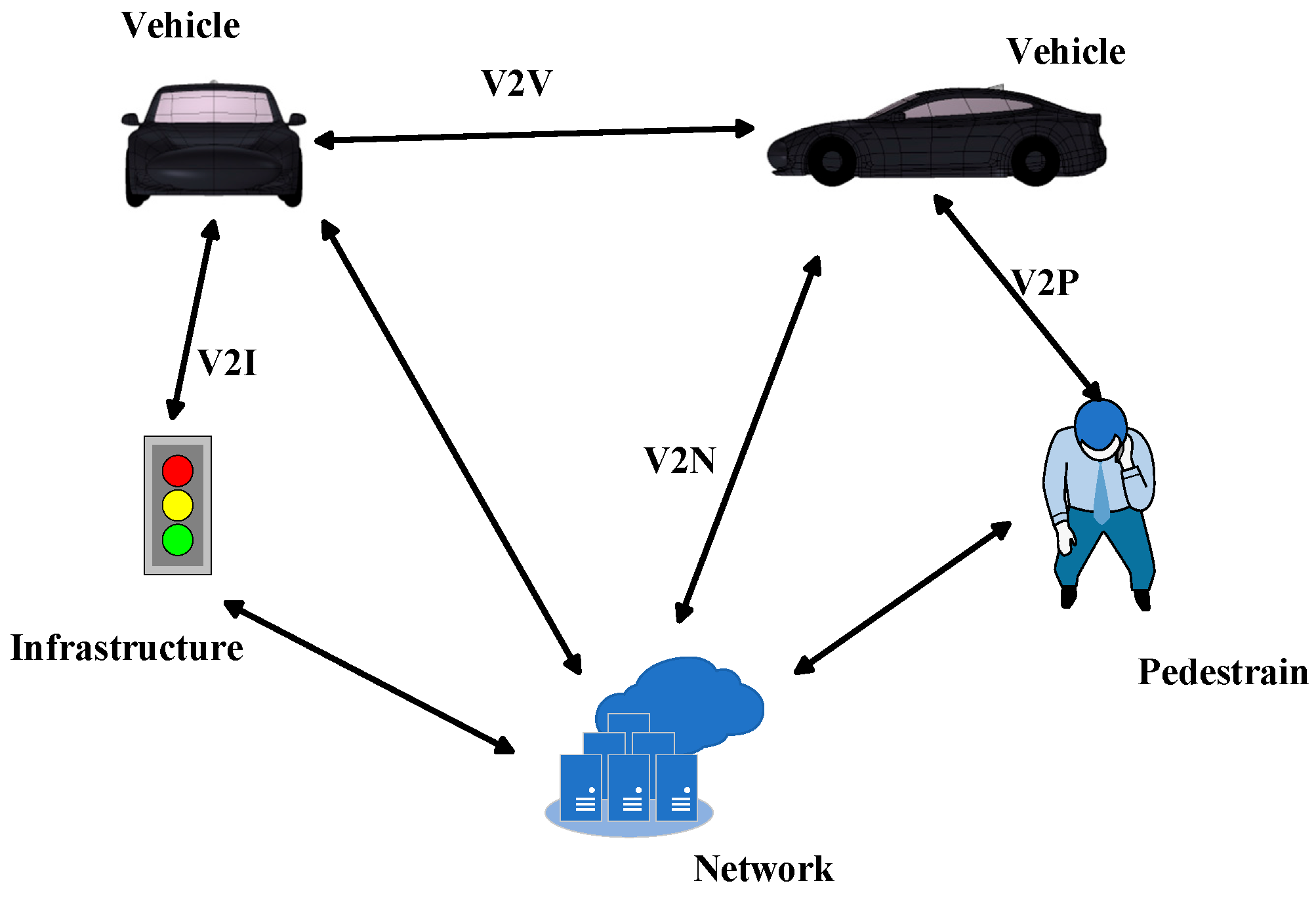
1. Introduction
2. Model Building
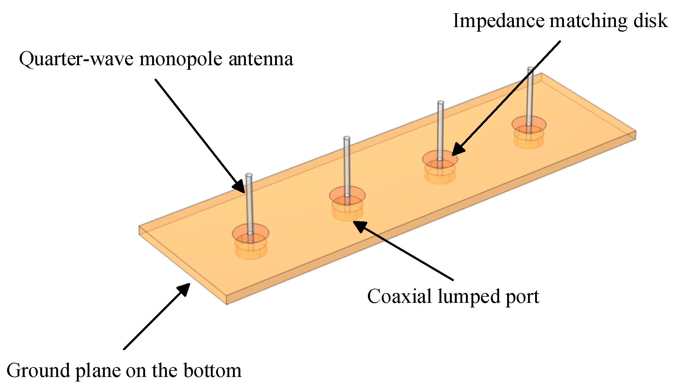
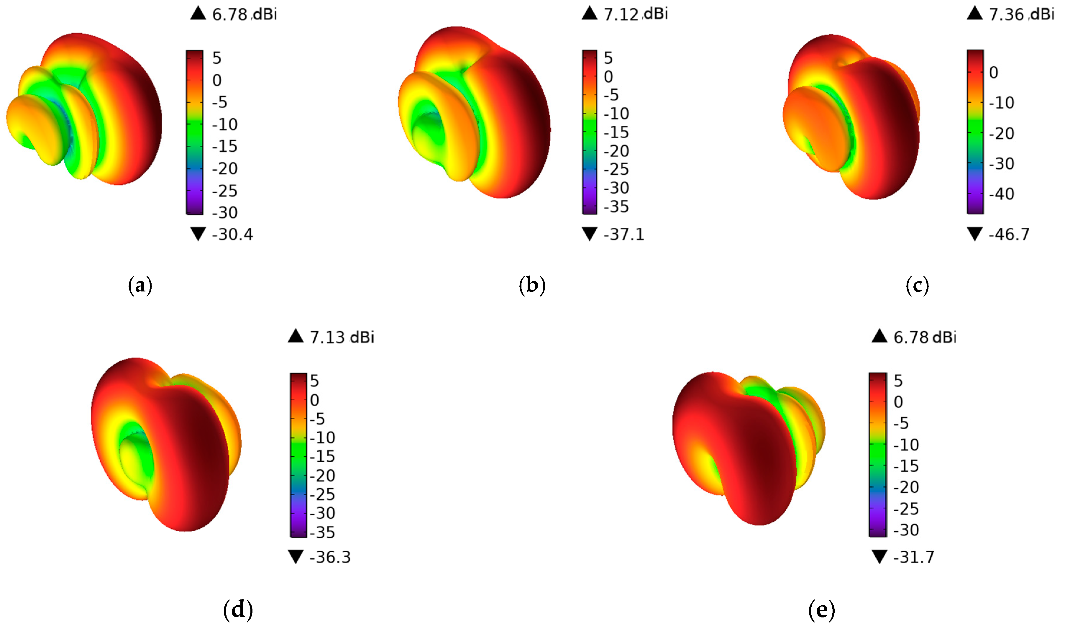
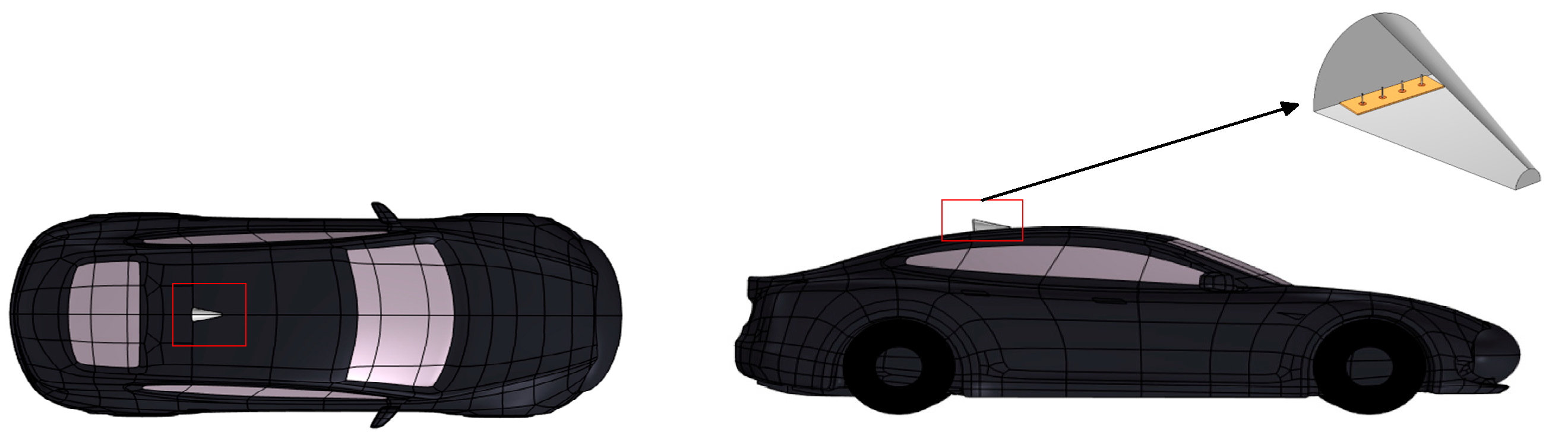
2.1. V2V Antenna Model
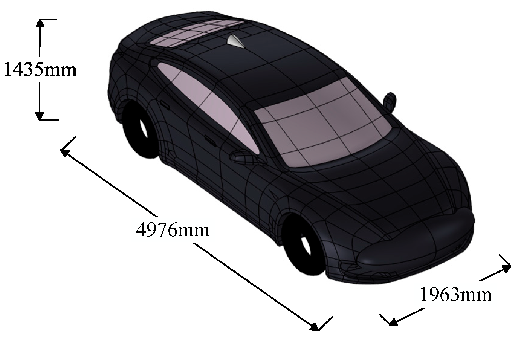
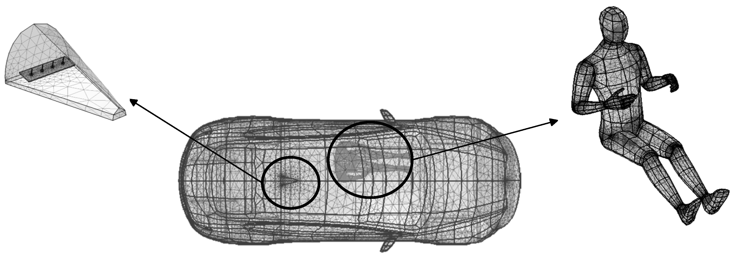
2.2. The Vehicle Model
2.3. The Human Model
3. Methods and Principles of Human RF Electromagnetic Exposure Assessment
3.1. Theoretical Basis of Electromagnetic Field
3.2. Dielectric Parameters of Human Tissue
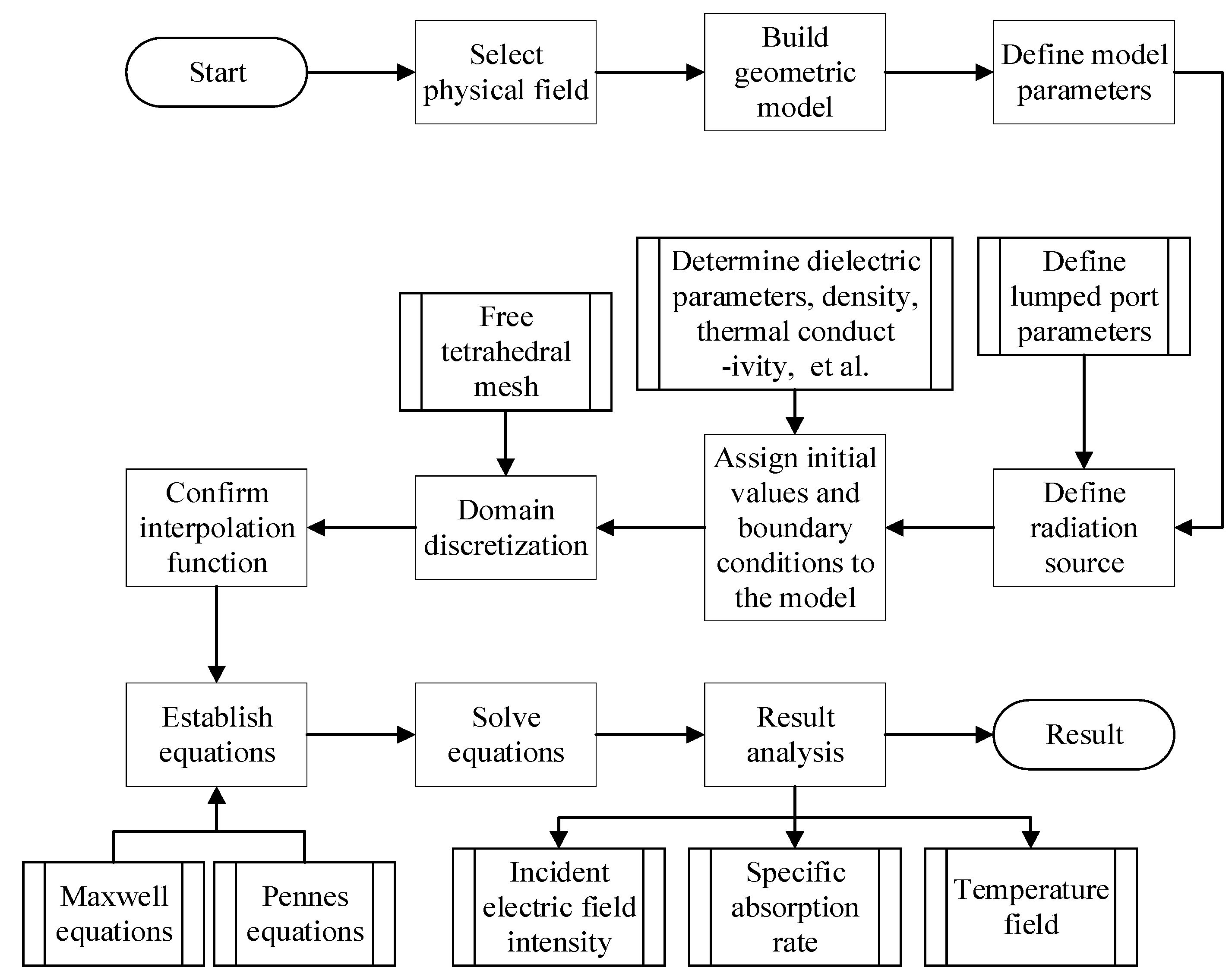
3.3. Simulation Calculation Methods
3.4. ICNIRP Guidelines
4. Safety Assessment of In-Vehicle Human EMF Exposure Under V2V Communications
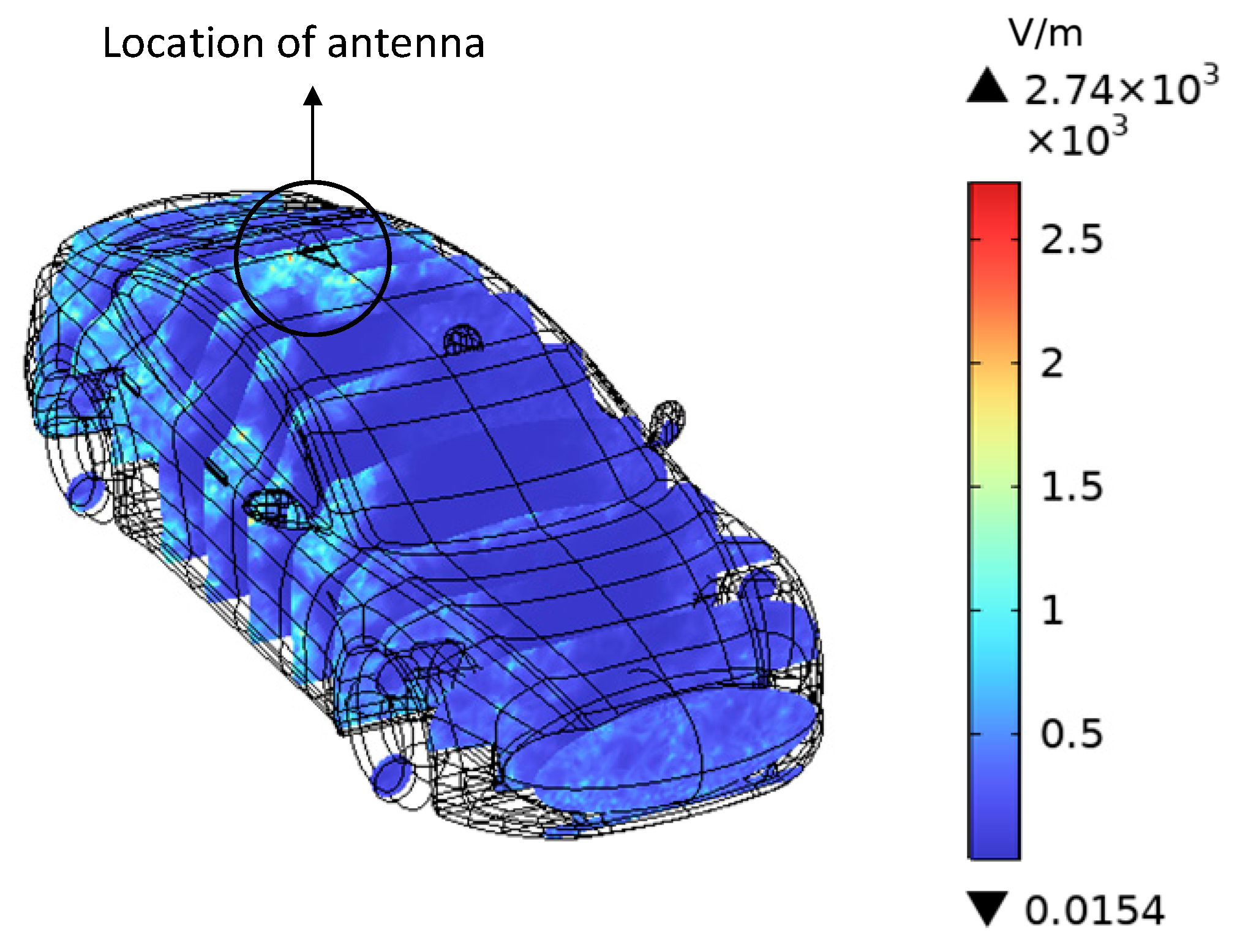
4.1. Electric Field Intensity Distribution of Vehicles
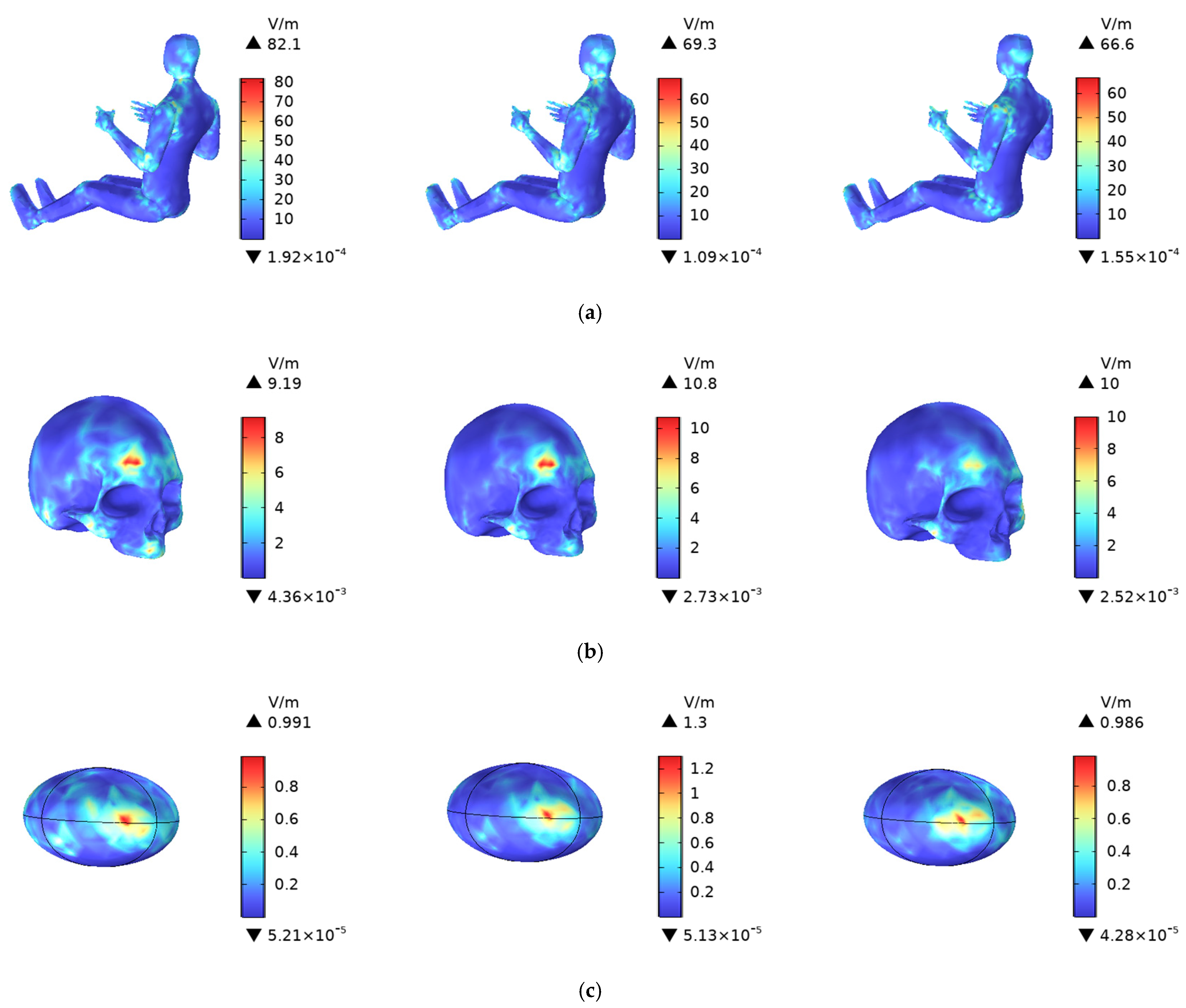
4.2. Human Electric Field Intensity Distribution
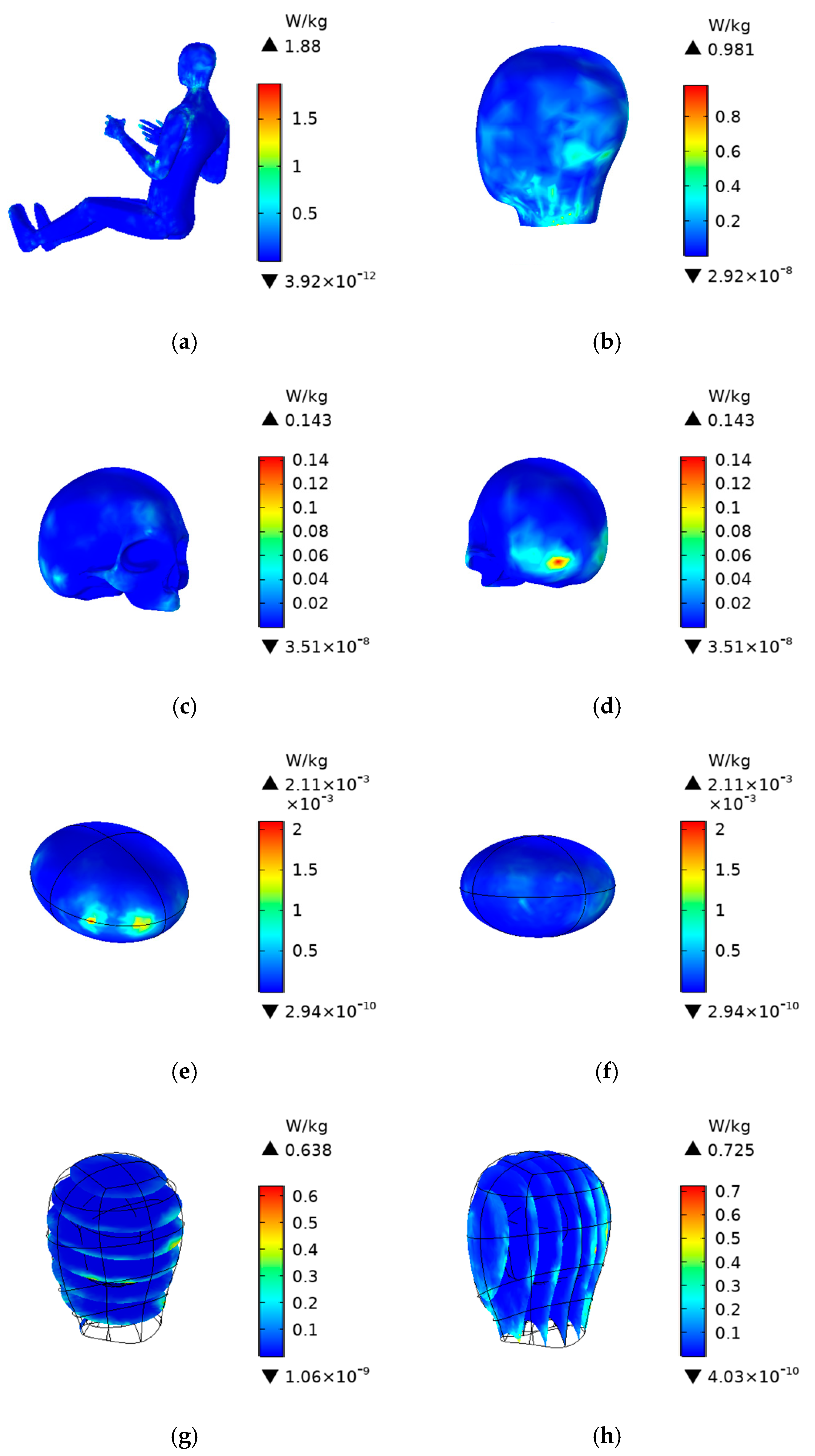
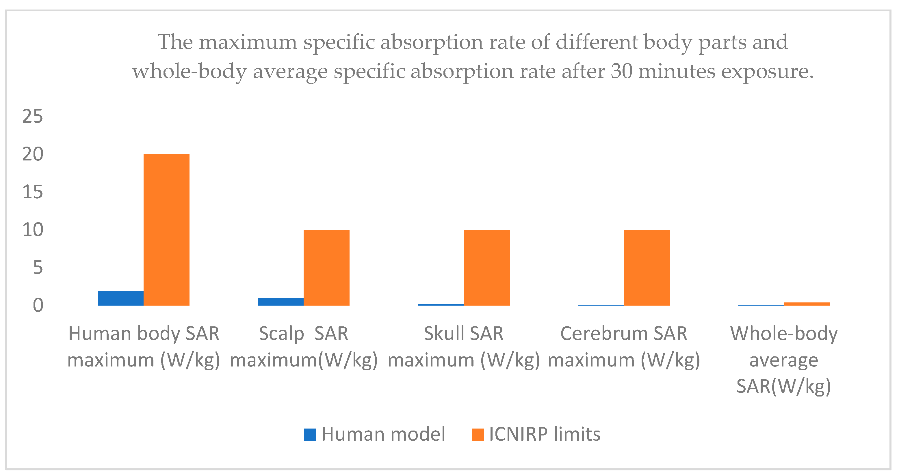
4.3. Human SAR Distribution
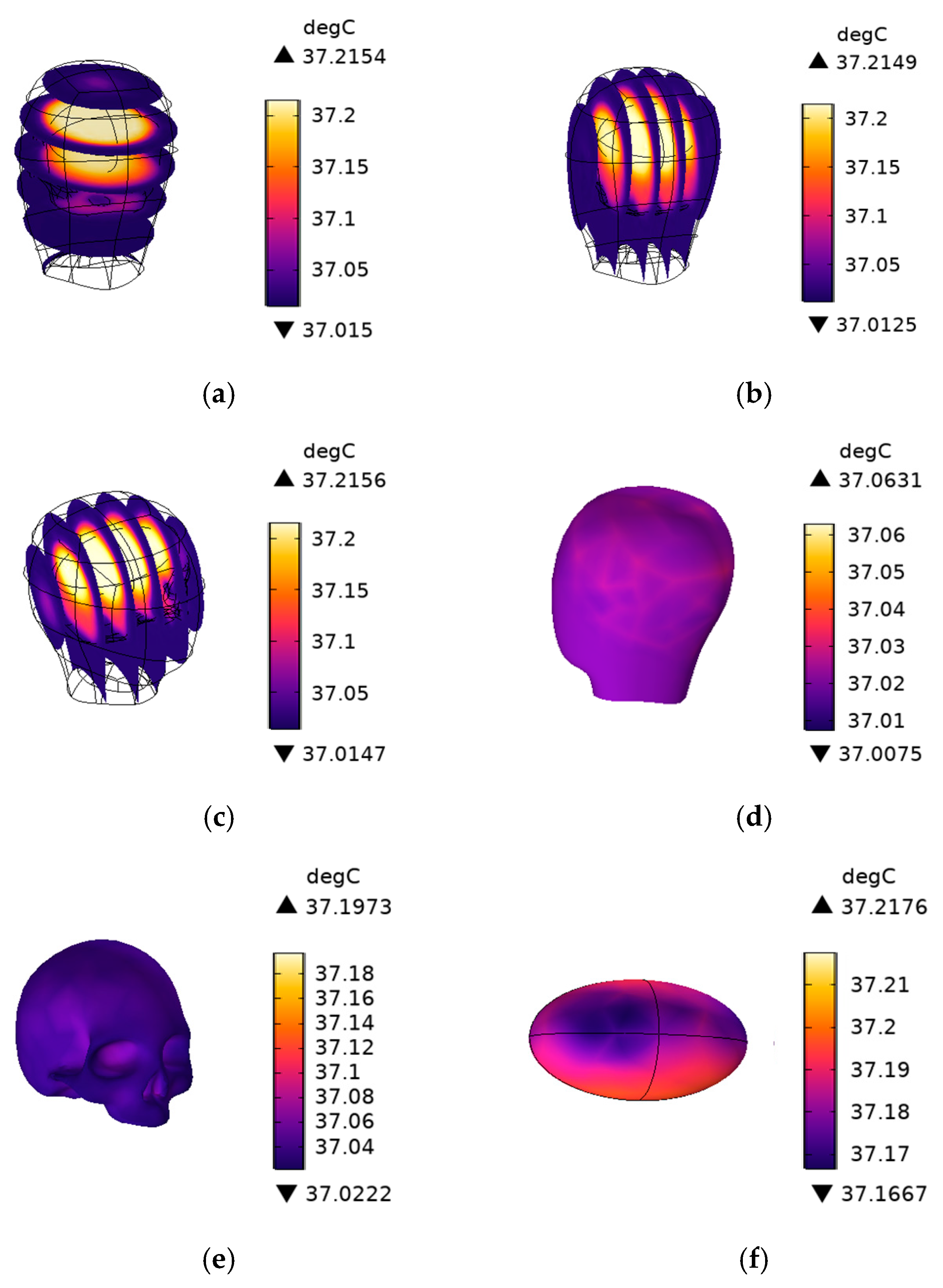
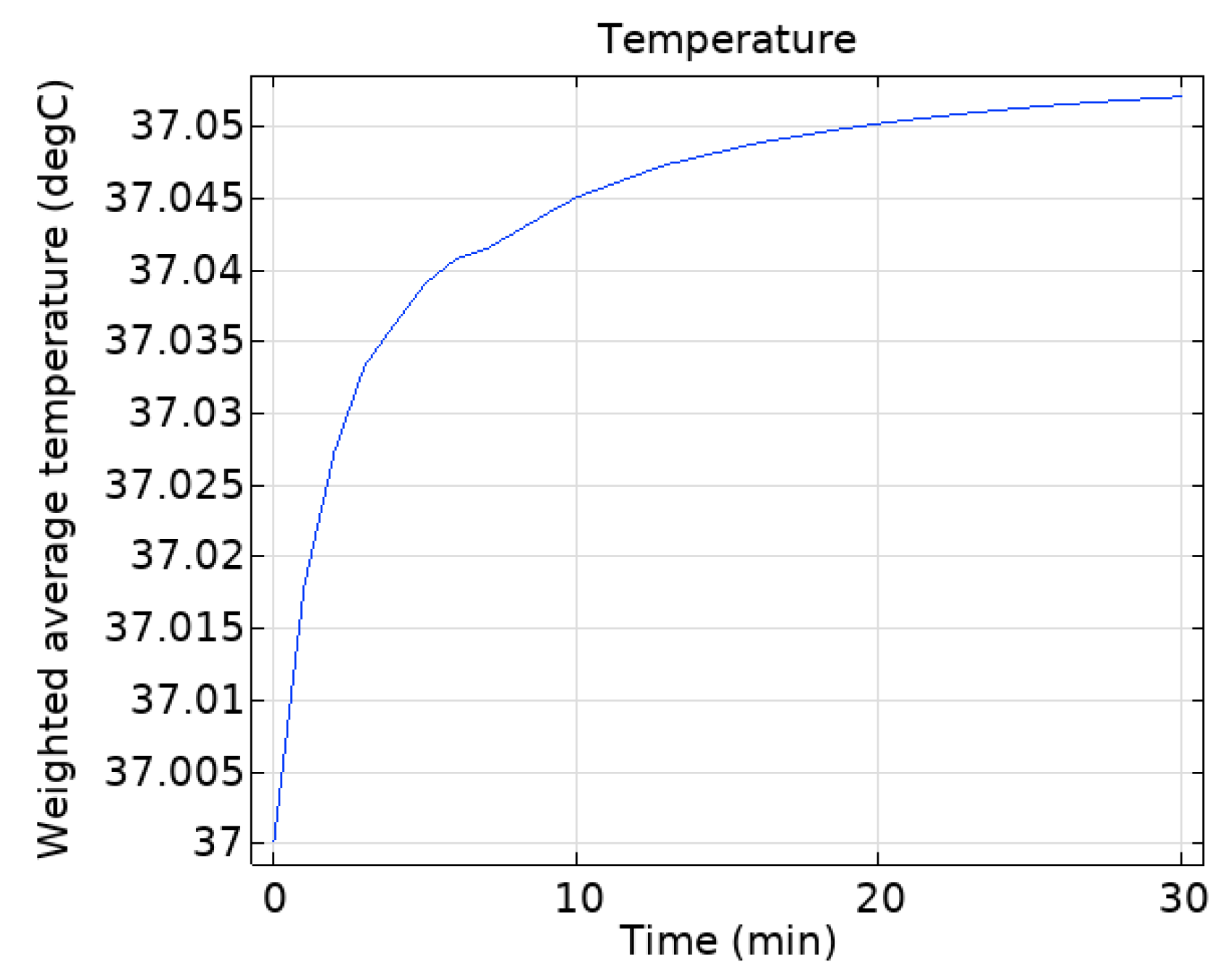
4.4. The Temperature Field Distribution of the Human Head
5. Conclusions
Author Contributions
Funding
Institutional Review Board Statement
Informed Consent Statement
Data Availability Statement
Conflicts of Interest
References
- Armstrong, R.; Dawson, L.; Rowell, A.J.; Marshman, C.A.; Ruddle, A.R. The Effect of Fully Electric Vehicles on the Low Frequency Electromagnetic Environment. In Proceedings of the 2015 IEEE International Symposium on Electromagnetic Compatibility (EMC), Dresden, Germany, 16–22 August 2015; pp. 662–667. [Google Scholar] [CrossRef]
- Ye, J.; Ge, X. Beam Management Optimization for V2V Communications Based on Deep Reinforcement Learning. Sci. Rep. 2023, 13, 20440. [Google Scholar] [CrossRef] [PubMed]
- Tan, J.; Luan, T.H.; Guan, W.; Wang, Y.; Peng, H.; Zhang, Y.; Zhao, D.; Lu, N. Beam Alignment in mmWave V2X Communications: A Survey. IEEE Commun. Surv. Tutor. 2024, 26, 1676–1709. [Google Scholar] [CrossRef]
- Moreno-Torres Concha, P.; Velez, P.; Lafoz, M.; Arribas, J.R. Passenger Exposure to Magnetic Fields Due to the Batteries of an Electric Vehicle. IEEE Trans. Veh. Technol. 2016, 65, 4564–4571. [Google Scholar] [CrossRef]
- Harris, L.R.; Zhadobov, M.; Chahat, N.; Sauleau, R. Electromagnetic Dosimetry for Adult and Child Models within a Car: Multi-Exposure Scenarios. Int. J. Microw. Wirel. Technol. 2011, 3, 707–715. [Google Scholar] [CrossRef]
- Wessapan, T.; Srisawatdhisukul, S.; Rattanadecho, P. Numerical Analysis of Specific Absorption Rate and Heat Transfer in the Human Body Exposed to Leakage Electromagnetic Field at 915 MHz and 2450 MHz. J. Heat Transf. 2011, 133, 051101. [Google Scholar] [CrossRef]
- Tognola, G.; Masini, B.; Gallucci, S.; Bonato, M.; Ravazzani, P. Numerical Assessment of RF Human Exposure in Smart Mobility Communications. IEEE J. Electromagn. RF Microw. Med. Biol. 2020, 5, 100–107. [Google Scholar] [CrossRef]
- Bonato, M.; Tognola, G.; Benini, M.; Gallucci, S.; Chiaramello, E.; Fiocchi, S.; Parazzini, M. Assessment of SAR in Road-Users from 5G-V2X Vehicular Connectivity Based on Computational Simulations. Sensors 2022, 22, 6564. [Google Scholar] [CrossRef]
- Schilling, L.M.; Bornkessel, C.; Hein, M.A. Human RF Electromagnetic Exposure to V2X-Communication. Adv. Radio Sci. 2022, 19, 233–239. [Google Scholar] [CrossRef]
- Shang, S.; Lu, M. Safety Assessment of Electromagnetic Environmental Exposure for GPS Antenna of Electric Vehicle. Int. J. Antennas Propag. 2024, 2024, 3192747. [Google Scholar] [CrossRef]
- Benini, M.; Gallucci, S.; Bonato, M.; Parazzini, M.; Tognola, G. Evaluation of Road User Radio-Frequency Exposure Levels in an Urban Environment from Vehicular Antennas and the Infrastructure in ITS-G5 5.9 GHz Communication. IEEE Access 2024, 12, 51419–51430. [Google Scholar] [CrossRef]
- Yang, Y.; Masini, B.M.; Vermeeren, G.; Van Den Akker, D.; Aerts, S.; Verloock, L.; Chiaramello, E.; Bonato, M.; Wiart, J.; Tognola, G.; et al. RF Exposure Assessment in ITS-5.9 GHz V2X Connectivity and Vehicle Wireless Technologies: A Numerical and Experimental Approach. IEEE Access 2024, 12, 186002–186021. [Google Scholar] [CrossRef]
- Stroobandt, B.; Van Bladel, H.; Veludo, A.F.; Deprez, K.; Aerts, S.; Verloock, L.; Thuróczy, G.; Politanski, P.; Polanska, K.; Tognola, G.; et al. Auto-Induced Uplink 4G and 5G RF-EMF Exposure Assessment Using a Network Monitoring Application in Different Microenvironments across Seven European Countries. Environ. Res. 2025, 270, 121029. [Google Scholar] [CrossRef]
- Bazzi, G.; Cecchini, M.; Menarini, B.M.; Masini, B.M.; Zanella, A. Survey and perspectives of vehicular Wi-Fi versus sidelink cellular-V2X in the 5G era. Future Internet 2019, 11, 122. [Google Scholar] [CrossRef]
- Chletsou, A.; Newsom, E.; Papapolymerou, J. Experimental Characterization of a Helical Antenna Integrated in the Rear of a Vehicle for C-V2X Communications. IEEE J. Microw. 2023, 3, 1147–1153. [Google Scholar] [CrossRef]
- Ibrahim, A.S.; Aloi, D.N.; Kaur, A. Analysis of C-V2X Antenna Performance on Vehicular Panoramic Glass. Int. J. Antennas Propag. 2023, 2023, 6622850. [Google Scholar] [CrossRef]
- The International Commission on Non-Ionizing Radiation Protection. Guidelines for limiting exposure to electromagnetic fields (100 kHz to 300 GHz). Health Phys. 2020, 118, 483–524. [Google Scholar] [CrossRef]
- Haupt, R.L.; Kidder, C. Defining Phased Array Bandwidth. IEEE Aerosp. Electron. Syst. Mag. 2023, 38, 34–42. [Google Scholar] [CrossRef]
- ETSI EN 302 571 V2.1.1; Intelligent Transport Systems (ITS). Radiocommunications Equipment Operating in the 5855 MHz to 5925 MHz Frequency Band; Harmonised Standard Covering the Essential Requirements of Article 3.2 of Directive 2014/53/EU. ETSI: Sophia Antipolis, France, 2017.
- Zhang, Y.; Hu, J.; Yan, X.; Tu, H. The Prediction of Loss Tangent of Sewed Multilayer Fabric: Text. Res. J. 2022, 92, 1565–1577. [Google Scholar] [CrossRef]
- Grosinge, J.; Lasser, G.; Mecklenbraeuker, C.F.; Scholtz, A.L. Gain and Efficiency Measurement of Antennas for an Advanced Tire Monitoring System. In Proceedings of the 2010 IEEE International Symposium on Antennas and Propagation and CNC/USNC/URSI Radio Science, Toronto, ON, Canada, 12–16 July 2010; pp. 1–4. [Google Scholar] [CrossRef]
- GB/T 10000-2023; Human Dimensions of Chinese Adults. National Standard, China Institute of Standardization: Beijing, China, 2023.
- Lu, M.; Ueno, S. Comparison of the Induced Fields Using Different Coil Configurations during Deep Transcranial Magnetic Stimulation. PLoS ONE 2017, 12, e0178422. [Google Scholar] [CrossRef]
- Cole, K.S.; Cole, R.H. Dispersion and Absorption in Dielectrics I. Alternating Current Characteristics. J. Chem. Phys. 1941, 9, 341–351. [Google Scholar] [CrossRef]
- Cole; Kenneth, S. Dispersion and Absorption in Dielectrics II. Direct Current Characteristics. J. Chem. Phys. 1942, 10, 98–105. [Google Scholar] [CrossRef]
- Gabriel, C.; Gabriel, S.; Corthout, E. The Dielectric Properties of Biological Tissues: I. Literature Survey. Phys. Med. Biol. 1996, 41, 2231–2249. [Google Scholar] [CrossRef] [PubMed]
- Gabriel, S.; Lau, R.W.; Gabriel, C. The Dielectric Properties of Biological Tissues: II. Measurements in the Frequency Range 10 Hz to 20 GHz. Phys. Med. Biol. 1996, 41, 2251–2269. [Google Scholar] [CrossRef]
- Gabriel, S.; Lau, R.W.; Gabriel, C. The Dielectric Properties of Biological Tissues: III. Parametric Models for the Dielectric Spectrum of Tissues. Phys. Med. Biol. 1996, 41, 2271–2293. [Google Scholar] [CrossRef]
- IEEE C95.3-1991; IEEE Recommended Practice for the Measurement of Potentially Hazardous Electromagnetic Fields-RF and Microwave. IEEE: Piscataway, NJ, USA, 1991.
- IEEE C95.3-2002; IEEE Recommended Practice for Measurements and Computations of Radio Frequency Electromagnetic Fields with Respect to Human Exposure to Such Fields, 100 kHz–300 GHz. IEEE: Piscataway, NJ, USA, 2002. [CrossRef]
- Spiegel, R.J. A review of numerical models for predicting the energy deposition and resultant thermal response of humans exposed to electromagnetic fields. IEEE Trans. Microw. Theory Techn. 1984, 32, 730–746. [Google Scholar] [CrossRef]
- Pennes, H.H. Analysis of Tissue and Arterial Blood Temperatures in the Resting Human Forearm. J. Appl. Physiol. 1948, 1, 93–122. [Google Scholar] [CrossRef]
- Bhargava, D.; Leeprechanon, N.; Rattanadecho, P.; Wessapan, T. Specific Absorption Rate and Temperature Elevation in the Human Head due to Overexposure to Mobile Phone Radiation with Different Usage Patterns. Int. J. Heat Mass Transf. 2019, 130, 1178–1188. [Google Scholar] [CrossRef]
- Kim, H.Y.; Kim, H.G. A Hexahedral-Dominant FE Meshing Technique Using Trimmed Hexahedral Elements Preserving Sharp Edges and Corners. Eng. Comput. 2022, 38, 4307–4322. [Google Scholar] [CrossRef]
- Conchin Gubernati, A.; Freschi, F.; Giaccone, L.; Scorretti, R. Analysis of Numerical Artifacts Using Tetrahedral Meshes in Low Frequency Numerical Dosimetry. Appl. Sci. 2022, 12, 6526. [Google Scholar] [CrossRef]
- The International Commission on Non-Ionizing Radiation Protection. Guidelines for limiting exposure to time-varying electric, magnetic, and electromagnetic fields (up to 300 GHz). Health Phys. 1998, 74, 494–522. [Google Scholar]
- The International Commission on Non-Ionizing Radiation Protection. Guidelines for limiting exposure to time-varying electric and magnetic fields (1 Hz to 100 kHz). Health Phys. 2010, 99, 818–836. [Google Scholar] [CrossRef] [PubMed]


| Name | Relative Permittivity | Relative Permeability | Electrical Conductivity (S/m) |
|---|---|---|---|
| Quarter-wave monopole antenna | 1 | 1 | |
| Coaxial lumped port | 3.38 | 1 | 0 |
| Dielectric substrate | 3.38 | 1 | 0 |
| Unit Phase (α) | Lumped Port 1 | Lumped Port 2 | Lumped Port 3 | Lumped Port 4 |
|---|---|---|---|---|
| −90 | 0 | −90 | −180 | −270 |
| −45 | 0 | −45 | −90 | −135 |
| 0 | 0 | 0 | 0 | 0 |
| 45 | 0 | 45 | 90 | 135 |
| 90 | 0 | 90 | 180 | 270 |
| Name | Relative Permittivity | Relative Permeability | Electrical Conductivity (S/m) | (kg/m3) | k (W/(m·°C)) | C (J/(kg·°C)) |
|---|---|---|---|---|---|---|
| aluminum alloy | 1 | 1 | 2730 | 44.5 | 475 | |
| glass | 4.2 | 1 | 2210 | 1.4 | 730 | |
| carbon fiber | 2 | 1 | 5000 | 100 | 5 | 1.2 |
| Name | Human Model (mm) |
|---|---|
| Head height | 217 |
| Head length | 180 |
| Head breadth | 148 |
| Human Tissues | Relative Permittivity | Electrical Conductivity (S/m) |
|---|---|---|
| Scalp | 35.03 | 3.80 |
| Skull | 9.97 | 1.22 |
| Brain Grey Matter | 43.86 | 5.10 |
| Brain White Matter | 32.52 | 3.58 |
| Cerebrospinal Fluid | 60.28 | 8.00 |
| Cerebrum | 45.55 | 5.56 |
| Skin | 35.03 | 3.80 |
| Bone | 15.32 | 2.19 |
| Muscle | 48.35 | 5.08 |
| Fat | 4.95 | 0.30 |
| Blood | 52.36 | 6.65 |
| Trunk | 31.20 | 3.60 |
| Human Tissues | (kg/m3) | k (W/(m·°C)) | C (J/(kg·°C)) | (W/m3) | (s−1) |
|---|---|---|---|---|---|
| Scalp | 1125 | 0.42 | 3600 | 1620 | 0.02 |
| Skull | 1990 | 0.37 | 3100 | 610 | 0.00046 |
| Cerebrum | 1038 | 0.53 | 3650 | 7100 | 0.00883 |
| Exposure Scenario | Frequency Range | Whole-Body Average SAR (W·kg−1) | Local Head/Torso SAR (W·kg−1) | Local Limb SAR (W·kg−1) |
|---|---|---|---|---|
| Occupational | 100 kHz–6 GHz | 0.4 | 10 | 20 |
| General public | 100 kHz–6 GHz | 0.08 | 2 | 4 |
| Human Model | ICNIRP Limits | |
|---|---|---|
| Human body SAR maximum (W/kg) | 1.88 | 20 |
| Scalp SAR maximum (W/kg) | 0.981 | 10 |
| Skull SAR maximum (W/kg) | 0.143 | 10 |
| Cerebrum SAR maximum (W/kg) | 0.00211 | 10 |
| Whole-body average SAR (W/kg) | 0.008728 | 0.4 |
| Head temperature rise maximum (°C) | 0.2176 | 1 |
Disclaimer/Publisher’s Note: The statements, opinions and data contained in all publications are solely those of the individual author(s) and contributor(s) and not of MDPI and/or the editor(s). MDPI and/or the editor(s) disclaim responsibility for any injury to people or property resulting from any ideas, methods, instructions or products referred to in the content. |
© 2025 by the authors. Licensee MDPI, Basel, Switzerland. This article is an open access article distributed under the terms and conditions of the Creative Commons Attribution (CC BY) license (https://creativecommons.org/licenses/by/4.0/).
Share and Cite
Wang, S.; Lu, M. Assessment of RF Electromagnetic Exposure to Car Driver from Monopole Array Antennas in V2V Communications Considering Thermal Characteristics. Sensors 2025, 25, 3247. https://doi.org/10.3390/s25103247
Wang S, Lu M. Assessment of RF Electromagnetic Exposure to Car Driver from Monopole Array Antennas in V2V Communications Considering Thermal Characteristics. Sensors. 2025; 25(10):3247. https://doi.org/10.3390/s25103247
Chicago/Turabian StyleWang, Shirun, and Mai Lu. 2025. "Assessment of RF Electromagnetic Exposure to Car Driver from Monopole Array Antennas in V2V Communications Considering Thermal Characteristics" Sensors 25, no. 10: 3247. https://doi.org/10.3390/s25103247
APA StyleWang, S., & Lu, M. (2025). Assessment of RF Electromagnetic Exposure to Car Driver from Monopole Array Antennas in V2V Communications Considering Thermal Characteristics. Sensors, 25(10), 3247. https://doi.org/10.3390/s25103247